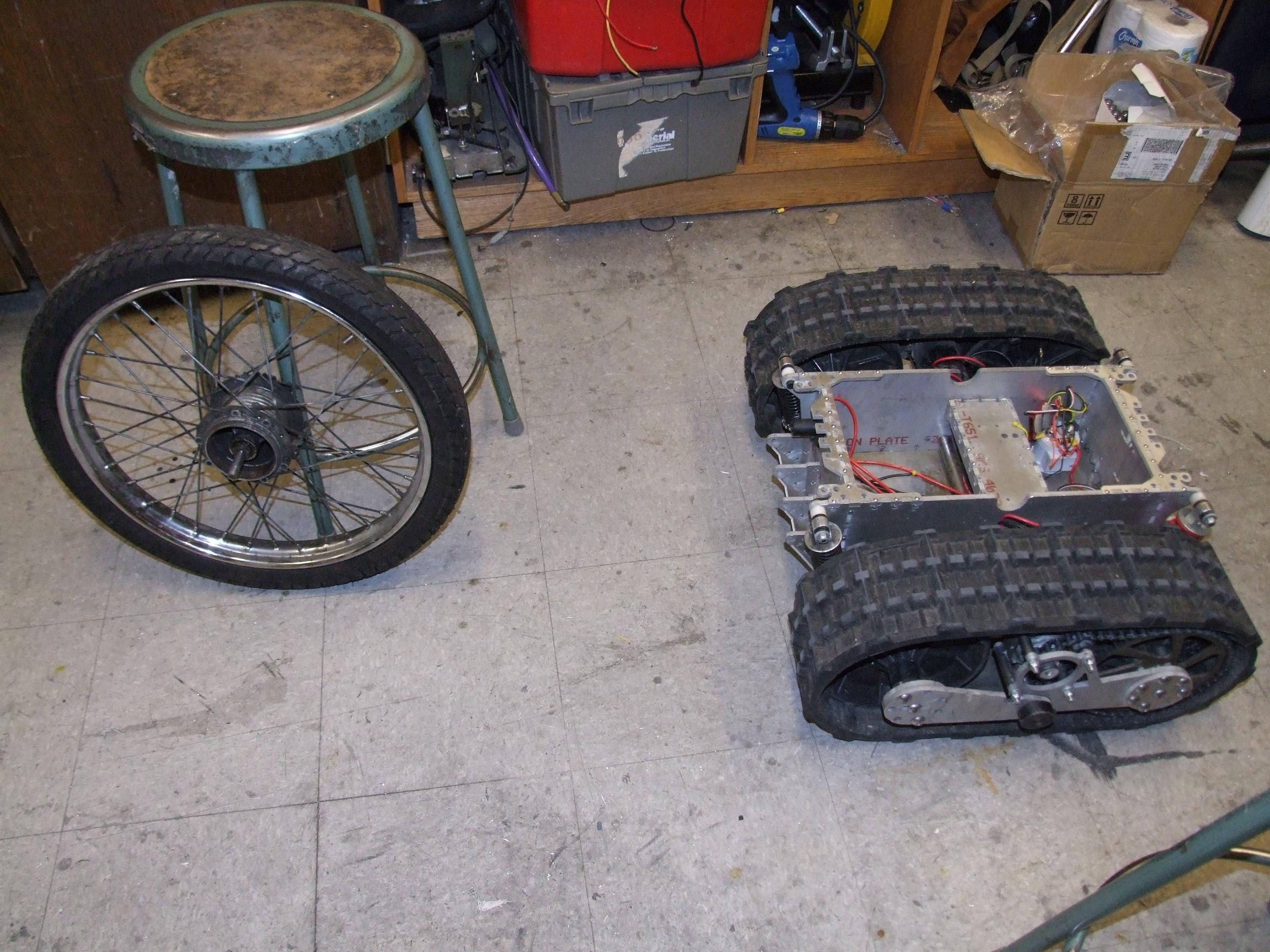
Land-Bear-Shark: I’m getting closer to blowing it up again

I’m starting to run out of things to work on to put off the software, which would require a substantial rewrite in order to change the signalling protocol over to R/C servo style PWM to accomodate the Hobbyking cartrollers. In the end it will be simpler, but still…. software. That’s only things that closet electronics engineers do. Otherwise, I’m taking so long on this that my load cells are probably going to arrive before I wire everything back up, but perhaps that’s just me subconsciously pulling towards trying to get that version working and skipping this steering-sense-only stopgap solusion. What I’ve also discovered to my potential dismay is that the HK cartrollers will just explode as soon as I actually get on the thing, so maybe I should start making room for the Kelly controllers again, or have another solution on hand…

Decisions, decisions. And pictures:

Speaking of closet EEs, check out these sensor holder boards by Shane. I’ve been meaning to make a clean, permanent mounting solution for my Hall sensors for a while, but just Never Got Around To It.  These are external mounts – they face inwards into the can, and the slots make for adjustable timing (also addressed in that post, and an interesting read for anyone else wondering why their motor doesn’t reverse).

Normally, I’m a fan of the internal slot-mounted sensor. For the SK motors, though, I would have had to mount them outside the motor because the slots are too narrow, so I got to test drive these mounts first.

Boards are nice, but that still doesn’t change the fact that the motor mounts I built have no provisions for attaching the boards. That’s fine, I’ll 3d print a little mounting ring thing.

Originally designed with 3 notches to fit the sensors by themselves (without a Nice Board), this mounting ring is aligned by the conical portion of the motor face, and protrudes very slightly past the end of it. This means when I tighten down the motor mounting screws, the ring is firmly secured by a taper fit. The whole thing is actually capable of rotating for sensor timing – with the sensor board’s mounting slots, it’s a bit redundant. A notch in one end lets the motor wiring through, and the two holes in the top face secure the sensor board.

Make-a-Bot is now on its last meter of ABS filament. Uh oh…

Sensor board attached and wired. I found some Nice 5-pin Cable that had a tension strand and braided shield. It’s a bit large and overkill for the task, but hey, 5 pin cable.

On the other end of the cable, I spliced in a standard R/C car motor sensor cable (ROAR 8.8.1.3 standard) I picked up with a Hobbyking order.

The next step was to test the motors. Because I don’t know if the sensors are actually in the right position or not, this was a game of applying gentle throttle to see if the motor would spin smoothly. For a fixed sensor input combination, there are 6 motor wire combinations to try, 2 of which work.

Hmm, well this doesn’t bode well.

I probably shouldn’t have tried to sensor-find on the full 22 volts. The SK motors have an internal resistance of like 30 milliohms, which means at 20-something volts, infinity amps tries to flow. If the sensor to phase relation isn’t correct, then the controller tries to flow infinity amps vibrating the motor around. The result is a literal popping sound as one leg of the power board detonates.

Luckily, I have a spare HK cartroller (the one that I took apart and beat up), but the fact that these exploded without even running the vehicle proper yet probably means it’s not going to end well. The motors are simply too low-resistance for a non-current-controller driver of this size to handle well.

After this, I decided that sensor finding on 11.1v might be better.

With the sensor-phase combo “found”, I timed the motors by measuring the DC current draw while rotationally adjusting the sensor mount. The point of optimal timing in one direction is represented by minimum current draw.

As Shane found out, optimally timing the motor for one direction using sensors like this does not mean they will be good for reverse at all. Due to a combination of factors such as sensor hysteresis, motor magnet field leakage, sensing distance, etc. the timing in reverse will be very far off – as much as an entire sensor state.

This means LBS will be able to reverse using the HK cartrollers, but very rudimentarily and only with extremely high current draw due to the non-optimal timing. This probably just translates into more death for the cartrollers.

Once the Band of Optimal Timing was located, the sensor mounts were fixed in place by tightening the motor mounting screws.

After wrapping the whole package up and potting the sensors to make them a little more waterproof, it was time to mount the motors.

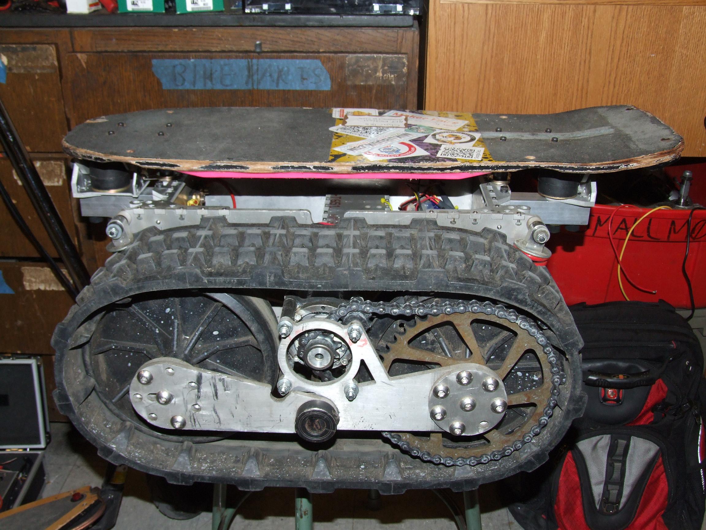
Hey, that’s an awfully small sprocket isn’t it? I didn’t know that they made things such as 6 and 7 tooth drive sprockets until I actually looked. The SK motors have a much higher torque constant than the CIM motors of yore, so I could bypass the CIMULINK reduction and just increase the single stage chain drive ratio by using a smaller sprocket. The motors have a RPMs-per-volt rating of 200 or thereabouts, so with a 7 tooth sprocket, resulting in a 6.4:1 ratio, the speed is approximate the same as the CIMs using the pre-reduction and 4.5:1 chain drive (about 18:1)

With the 7 tooth sprocket, the chain turned out to be essentially the correct length after I added a “halflink”, or one full pitch. There’s a small amount of slop, but it’s better than before, so I decided to not use a tensioner.

I verified that the motors were in fact still working after wrestling them into the track pods. After that, it was time to throw everything else back in. The batteries are in a different orientation this time – sitting flat instead of vertically side by side, and they have polycarbonate plates holding them from being jostled. Previously they were free to bounce around inside the cavity, which I can’t imagine was very good for them.

The next step is to Put The Arduino Back In and make some R/C based driving code – and detonate the cartrollers.
LandBearShark New Hinge Installation

This is the post where I take those CAD renderings from before and manifest them physically. I was able to assemble the entire new hinge today and test out the ride. Conclusion? A little soft, but the sandwich mounts I purchased were also the softest type on McMaster (50A durometer). Upgrading to the hardest type (70A) should make the board much stiffer. However, it behaves as expected, and the “pot wrench” coupling also works well.

I feel a little shameful for making yet another post where there is an instantaneous transition between CAD rendering and parts. High-school-me would have figured out how to make this new hinge solely from Home Depot aluminum angle and UHMW stock from McMaster-Carr, and early-college-years-me would have made long detailed posts filled with pictures of machining and musing about machine tool design.  So you guys over at Georgia Tech should post more pictures of your own waterjet pimping such that I feel less guilty :(

For people not in bed with the hydraulic intensifier, there’s places like Big Blue Saw which you should totally check out. That’s my promise: Every time I make a new build post involving waterjetted parts, I will spam Simon all over it.

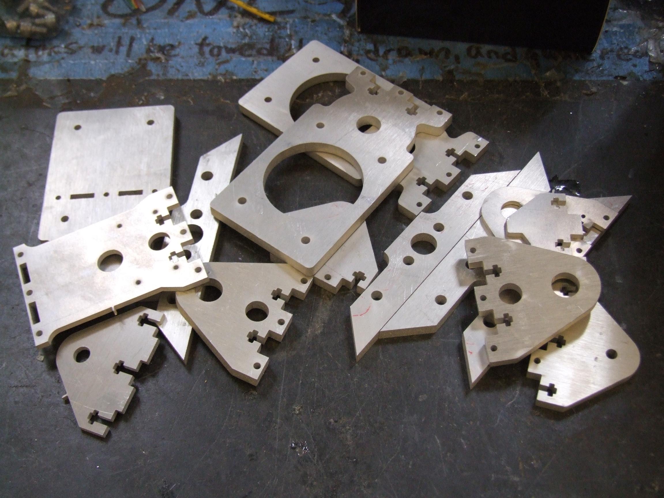
The parts above are cut from my giant eBay haul of 1/4″ aluminum plate, the same one that Straight RazEr was made from.  The potentiometer mount is 1/8″ and was cut from scrap plate.

Alright, enough guilt tripping. This is the “pot wrench” in real life. The bottom piece is two stacked 1/8″ plates that are pre-assembled with 4-40 tapped holes. Then, treating the resulting piece as solid, I threaded one of the large mounting holes 1/2″-13.

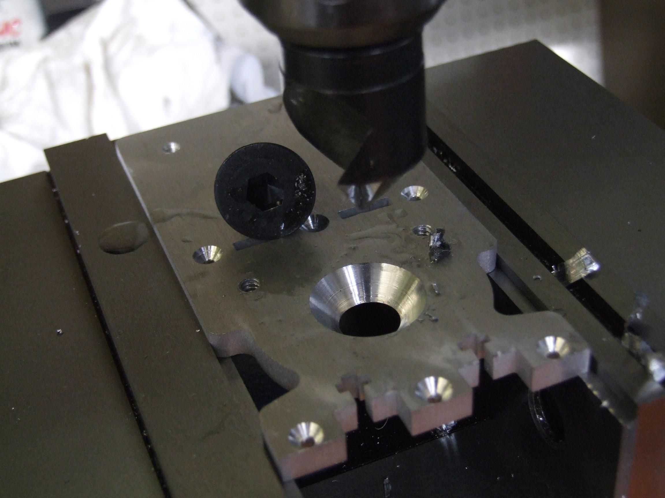
Because the top of the hinge is also the skateboard mount, all of the screws had to be countersunk. This was a problem: the massive 1/2″-13 flathead cap screw I ordered to secure the sandwich mounts needed a countersink that was 7/8″ across. Luckily, the Edge shop had a 1″ 82 degree countersink.

I later found out they make countersinks over 3″ diameter. What the hell are you countersinking that’s that large? Container ships?

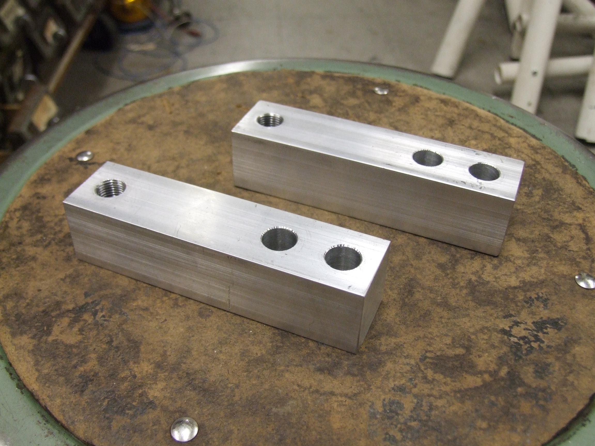
Because the load cells (Keli Electric SQBY 500lb type, as it turns out) haven’t arrived yet, nor am I in the mood to diddle with them, I made these temporary mock load cells with the same outer dimensions out of aluminum bar. They will provide the bridging connection between the hinge and the rest of the frame. The holes are tapped and cleared for 1/2″-13 screws.

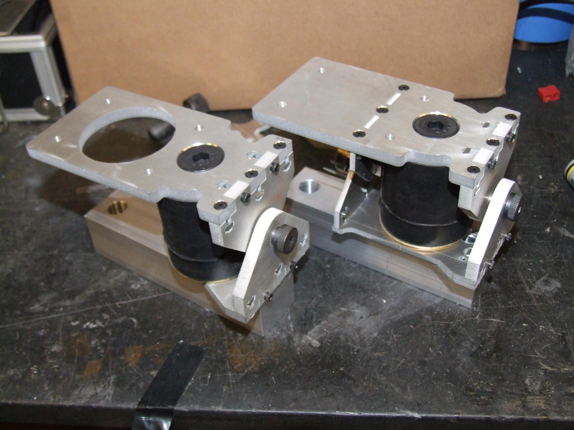
Here’s the front and rear hinge assemblies put together. The large shoulder screws solidly define the axis of pivot.

After the hinges were asssembled, I officially committed to the rebuild.

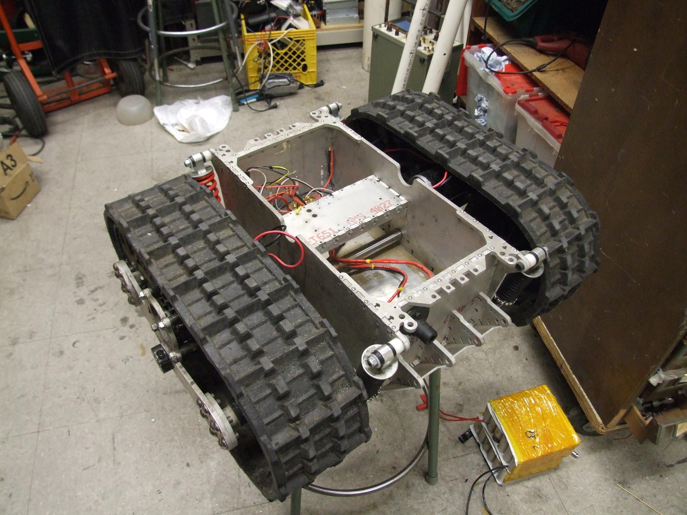
I tore out everything – all the electronics, and the batteries, and most non-fixed wiring. I blew out the interior (which was very much filled with dirt thrown around by the tracks) and cleaned up all the surfaces. The old hinges have also been removed.

One downside of the redesign is that I will lose my “dead rider switch” until the load cells come in and I can read them. So I’ll be keeping the throttle manually controlled for now – since I only need one channel in this case (assuming I can Do It Right) with the steering potentiometer, I might take advantage of the XBee socket on the 2.007 Standard Issue Arduino Carrier and make a simpler wireless link akin to the RazErBlades controller. That, in itself, would be pretty kickass.

This is too tempting. Way too tempting.

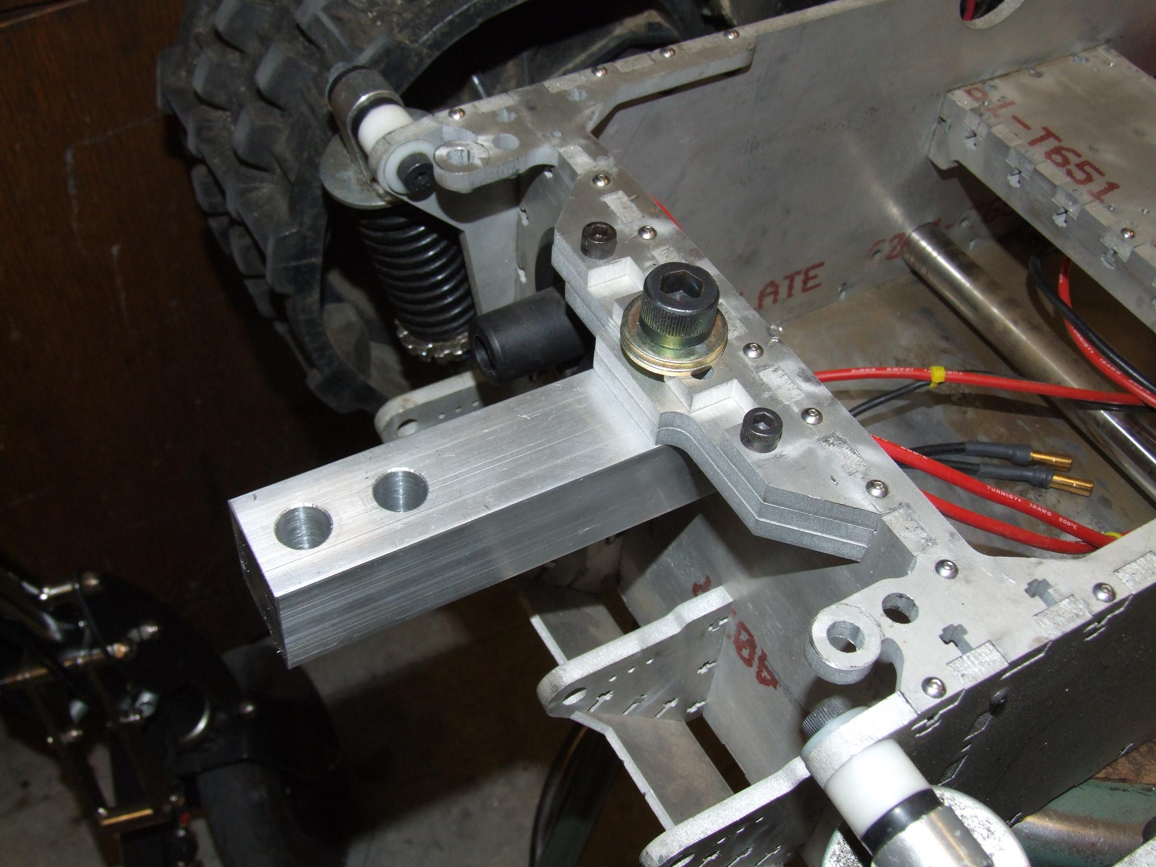
The fake load cells mount with a single Giant-Ass Cap Screw through the spacer plates and into the 1/2″-20 threaded hole. The spacer plates are individually retained by 1/4″-20 screws – the middle plate is a clearance hole and the bottom is threaded.

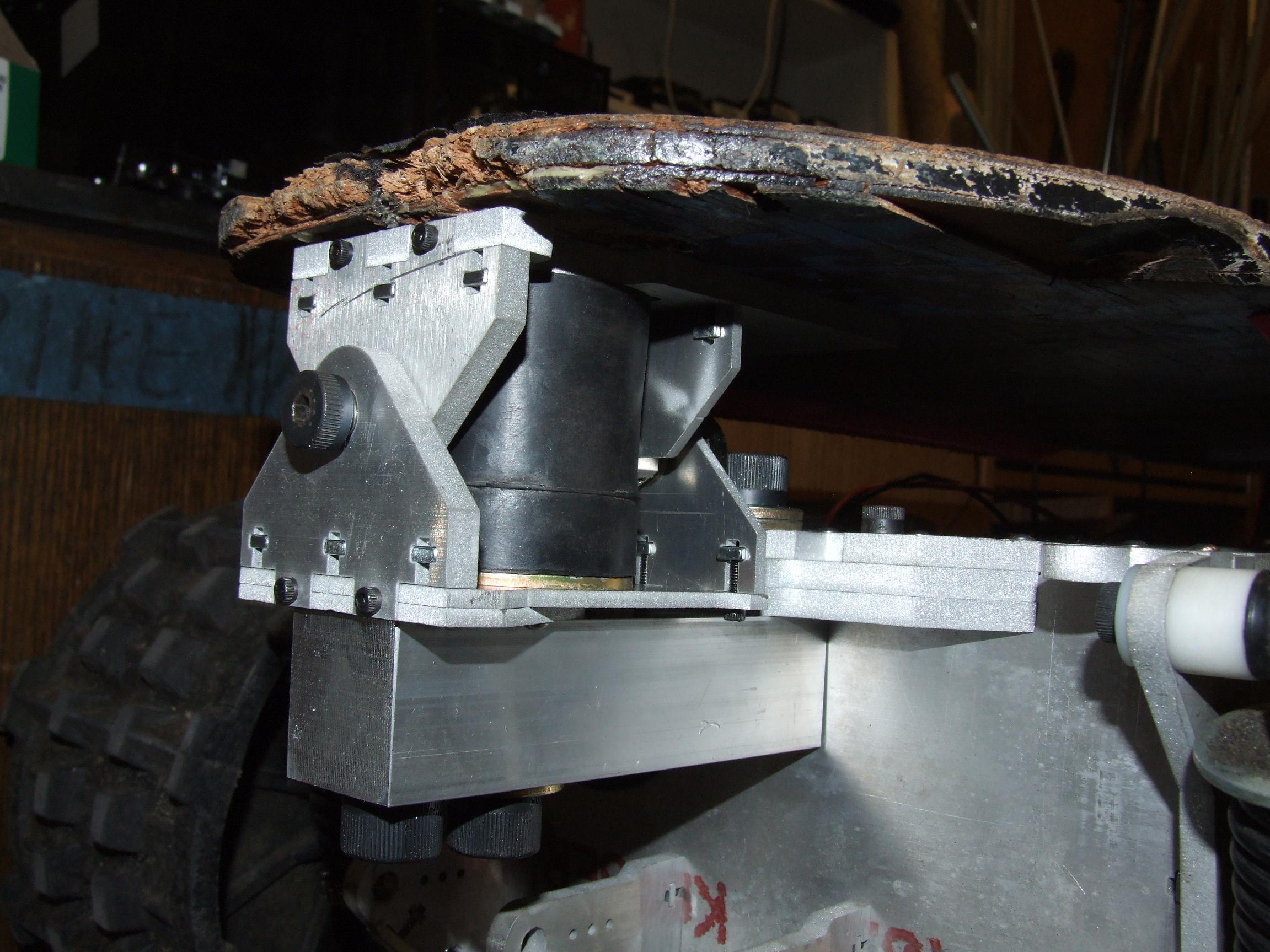
The hinge assembly drops on, and is secured from the bottom by two 1/2″-13 cap screws. The longer one (with the spacing washer) anchors the sandwich mount through the soon-to-be-real load cell. The other is threaded into the aluminum plate beneath it and stops flush with the top surface. Really only the former is needed, but I figured it was better for consistency.

Profile view of the new hinges. I guess they don’t stick out that much – not from this perspective. I will still make front and rear bumper-like structures to prevent banging the load cells into something first.

Jump testing on this assembly revealed that it is a little soft. There is much more travel available and there’s not a “hard stop” all of a sudden, so it mimics the ride of a rather softly-tuned longboard. The potentiometer mount works as designed, and after alot of jumping in the center of the board, the pot itself was not damaged.

Here’s a quick video showing a wiggle test of the new hinge assembly.

With the gory part of the hinge installation complete, I moved onto preparing the new motors.

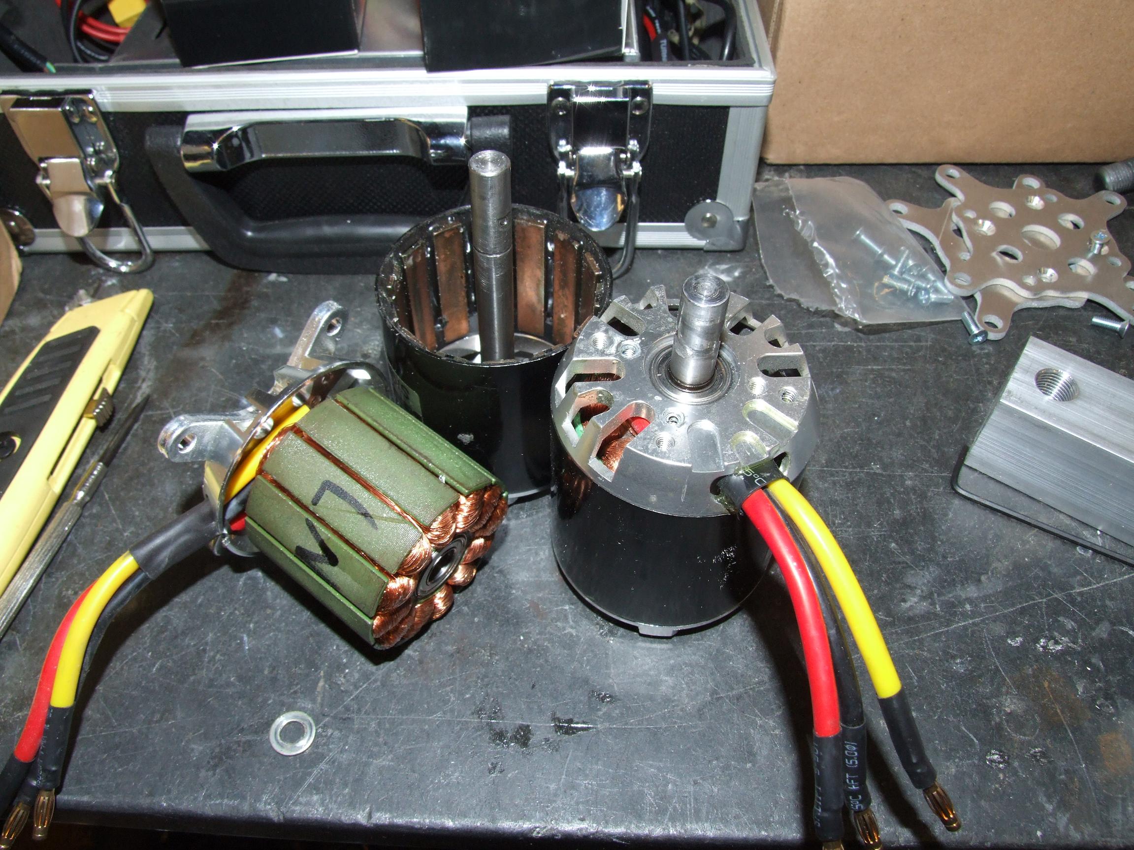
More properly, they are new old motors. These Turnigy SK 6374/200 motors are tinyKart’s current drive motors, but the abuse of a vehicle’s shocks and jolts coupled with the fact that these motors do not have the “can bearing” of newer designs means that they’re kind of beat to shit.  On one of them, the stator was completely loose and could be easily slipped off by hand. The other suffered from an axial misalignment of the can that caused it to grind on the stationary faceplate.

I cleaned out the stator bore and stator post of the first motor with some carburetor cleaner (which is like, death and AIDS dissolved in cancer), then reattached the stator with copious amounts of thin CA glue. The mechanically gimpy second motor was just shimmed until it stopped grinding on itself.

While they had high speed resonance issues at 40 volts on tinyKart, they seem to be comfortable with 20 volts, even in their slightly dinged condition.

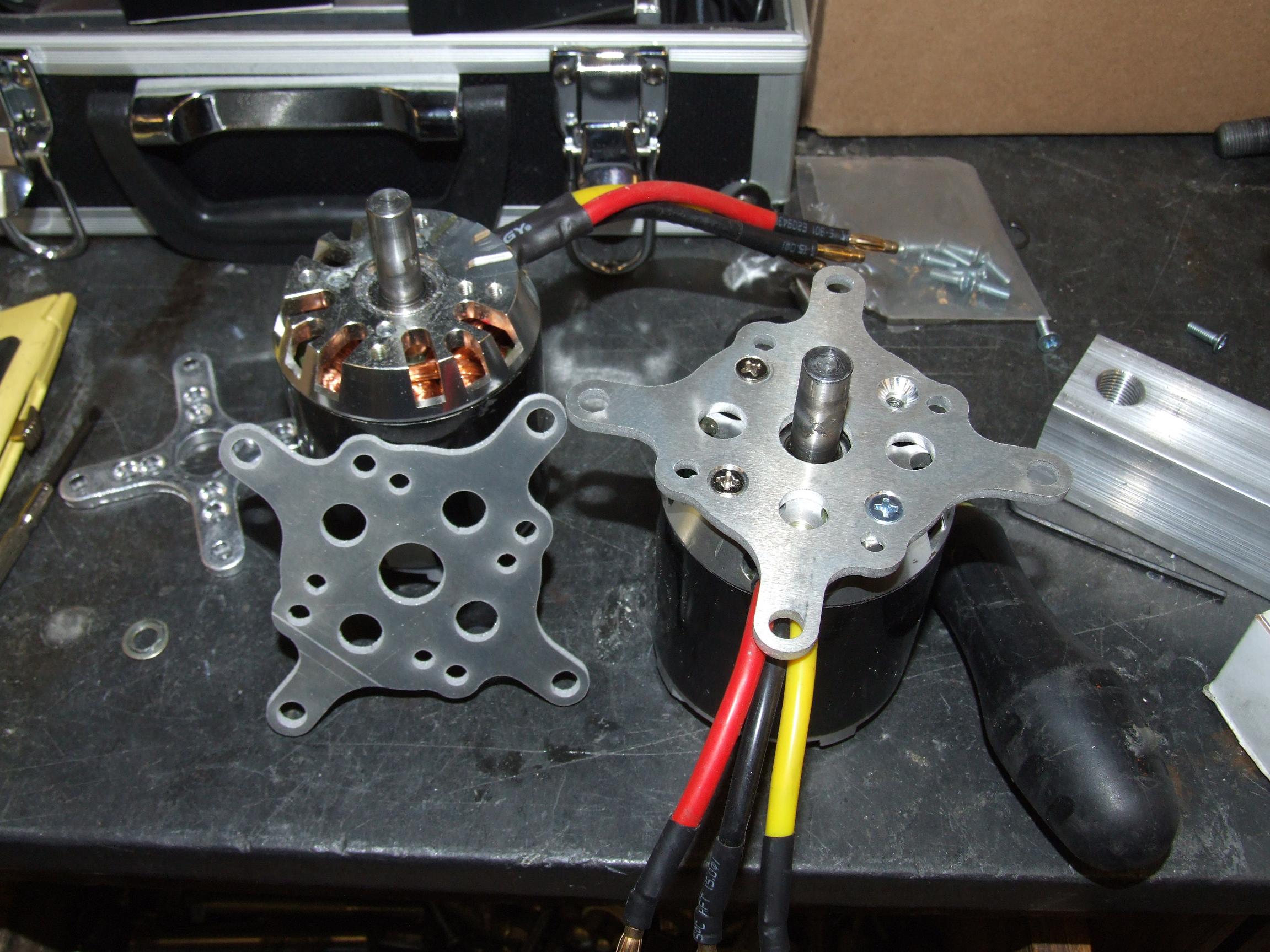
I made these motor mounts in conjunction with the rest of the parts. They have a semi-universal mounting pattern, fitting any of Hobbyking’s 63mm and 80mm motors. It means one day I can actually switch back to Real Melons, using the existing four mounting holes in the frame

What’s next? I need to actually perform the motor swap, but this might have to wait until I can figure out how to attach sensors to it. Unlike the 80mm motors, the stator tooth gaps on this motor are too narrow to jam a Hall-effect sensor in, unless the package was tiny. Therefore, despite the more iffy weather sealing ability, I will have to use externally-mounted sensors.

But it might be quite possible that sensorless is just fine…. I should try that.