i put dro on my mill

Some time last year, I bought a mill. I then proceeded to drive that mill solely by eye, backlash-riddled dials, and Sharpie marks forever and ever, like I was doing for a while as a plucky undergraduate. While pushing around, on the bench, the DRO kit that I bought not long after the mill. Vacuuming around it, carefully arranging workpieces around the kit, for the better part of a year.
Alright, I’m finally sick of doing that! With the weather being too cold again for me to want to work on the van piles, and Motorama around the corner again, I’m just gonna sit down and bang it all out over a few days. There’s a couple of parts I needed to fab up for the new Susquehanna Boxcar, for instance, not to mention a new 30Haul build (finally)!

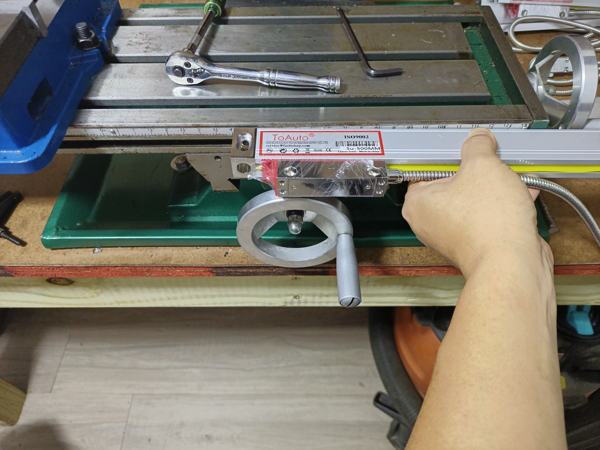
So here’s what we’re looking at. It’s a generic eBay scale kit with display that comes in a few sizes, and I picked two that are a little over the axis travel lengths. I chose to not integrate a Z-axis column readout (the usual 3-axis kit) because the quill has a little readout on it already.

I’m taking the slightly unusual step of mounting the X axis scale on the front of the bed. Usually, you’re supposed to mount them on the back of the bed, but this takes over an inch off the Y-axis travel. On a small machine, I would prefer to retain as much travel as I could.

Instead, I’m going to make some Bracketry to hang it off the front of the bed. I mean, not that ANY of the supplied generic aluminum channel/angle brackets fit this setup, since they are all cut for approximately Bridgeport-sized machines.
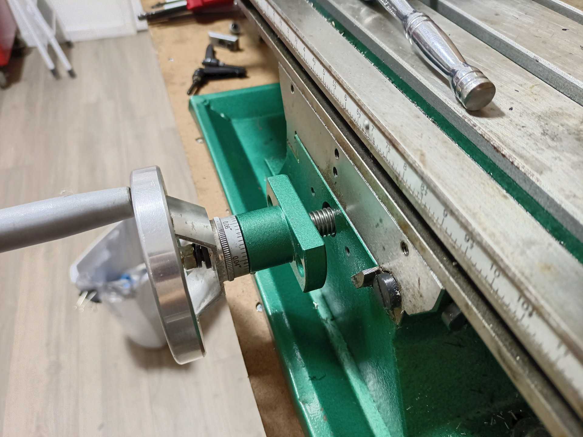
In positioning the scale at the front of the bed, I would have the issue of the scale and slide running into the Y-axis handwheel. But it turns out, you get approximately a free 3/4″ of additional travel simply by unscrewing the leadscrew mounting block from the front of the machine.

This standoff distance is the limit of full axial engagement of the leadscrew nut (mounted to the saddle) when the table is all the way at the back of the machine, so it’s not like at that point I made the thing hang on by one thread pitch. I simply used the extra screw length they already gave you!
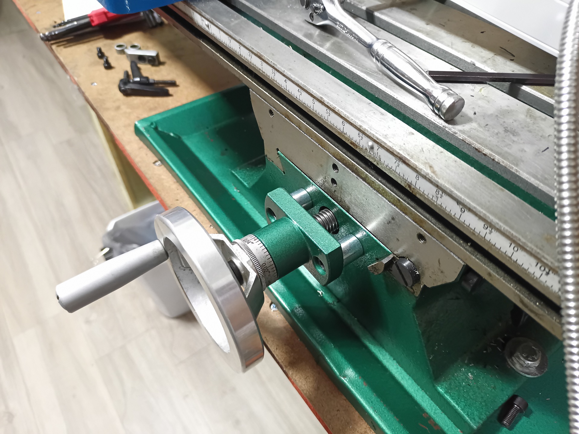
And just like that, an extra 18mm of travel is bought for the price of two steel spacers.

This wasn’t a precision surface here anyway, given that they powder coated it over. The “bonus” travel meant that only the readout slide would overhang the handwheel by a small amount, when the table is fully bottomed out towards the front of the machine, instead of the whole scale mashing into it.
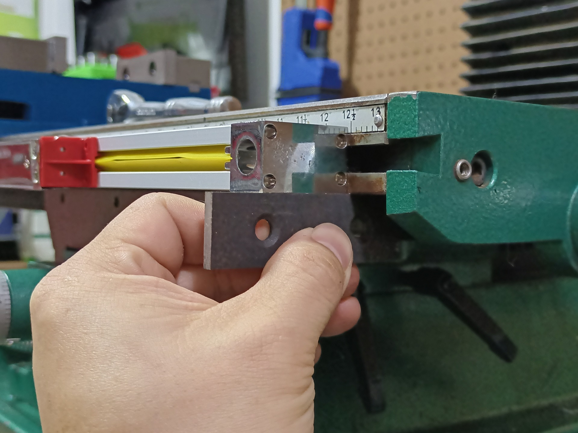
Other than that, installation of the X axis scale was fairly straightforward. I just lined up the bottom of the scale with the bottom of the table. A T-slot nut resides inside the mounting blocks, and the hole is slotted to give about 4mm of vertical slop tuning. It’s going to be a tighten-once affair anyhow.
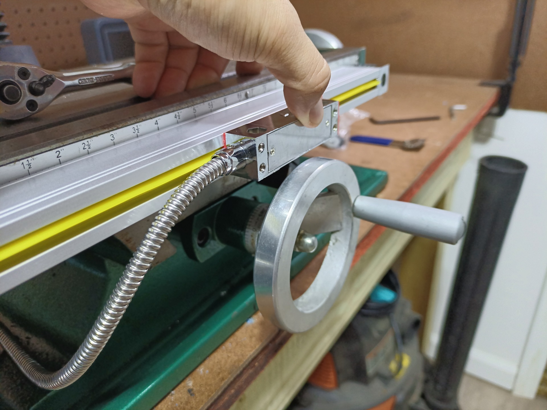
Now I had a solid look at where the slide will end up, and can design a small Bracketry to connect this to the saddle. The gap between the slide and Y-axis handwheel is about 3mm in the center.
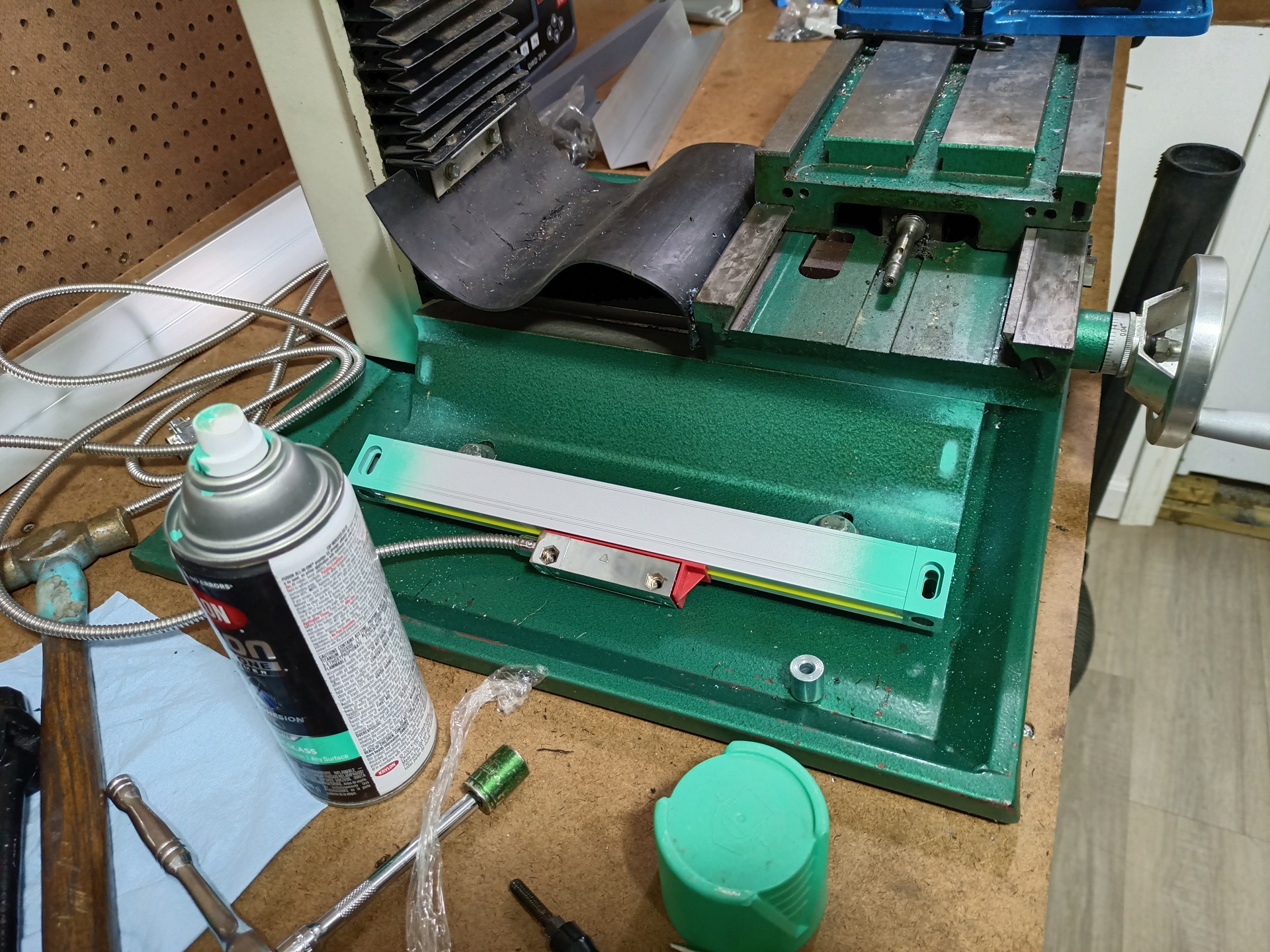
I got a start doing the same kind of size-up operation for the Y-axis scale. This one was going to be pretty awkward. The plan is to mount it at an angle on the side of the machine, but there’s not any good gauging surfaces to line it up. So, with some little welding magnets supporting it and a bubble level on the table surface, I got it to a place I thought would be the most ergonomic to fit up the Bracketry……. and hit the ends with a little bit of spraypaint to transfer the mounting pattern.

I then center-found the paint stains and drilled into the casting. I mean, the slots are there for adjustment, right!? As long as I wasn’t too far off on a length basis, the exact up-and-down placement isn’t too important now.
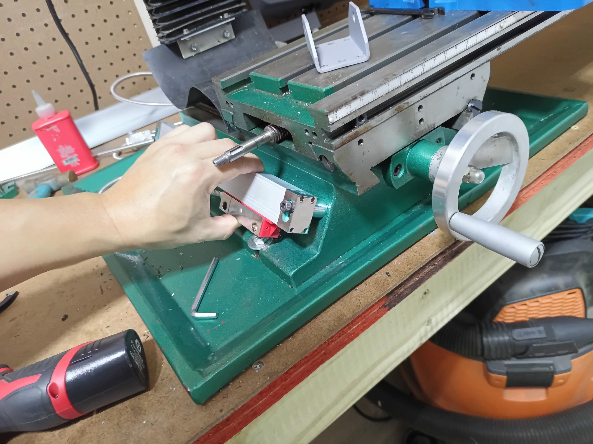
That actually worked way better than I expected. The same 18mm spacers stand off the scale from the machine. Now I had a few good gauging points to work with for making measurements. Usually, DRO slides are mounted with some thin, (relatively) flexible metal leaves and brackets to not transfer much force along the scales. I was just going to selectively 3D print them, so they’ll be inherently a little flexible.
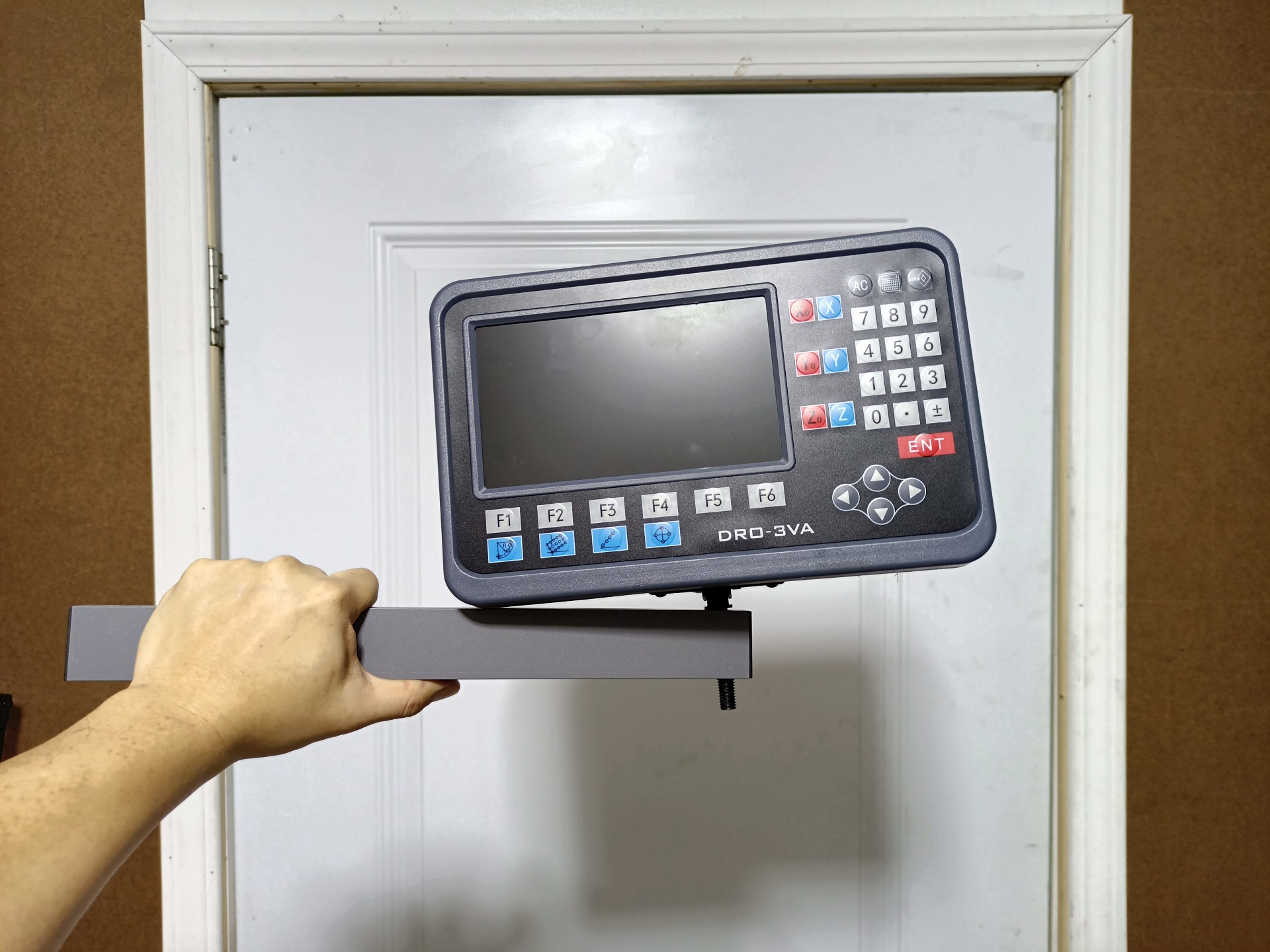
I moved onto doing the rest of the machine setup and oh my goodness you guys didn’t even TRY to line this up. I was legitimately unsure if the arm was meant to be mounted at some awkward angle, but ultimately I think these holes were supposed to line up…
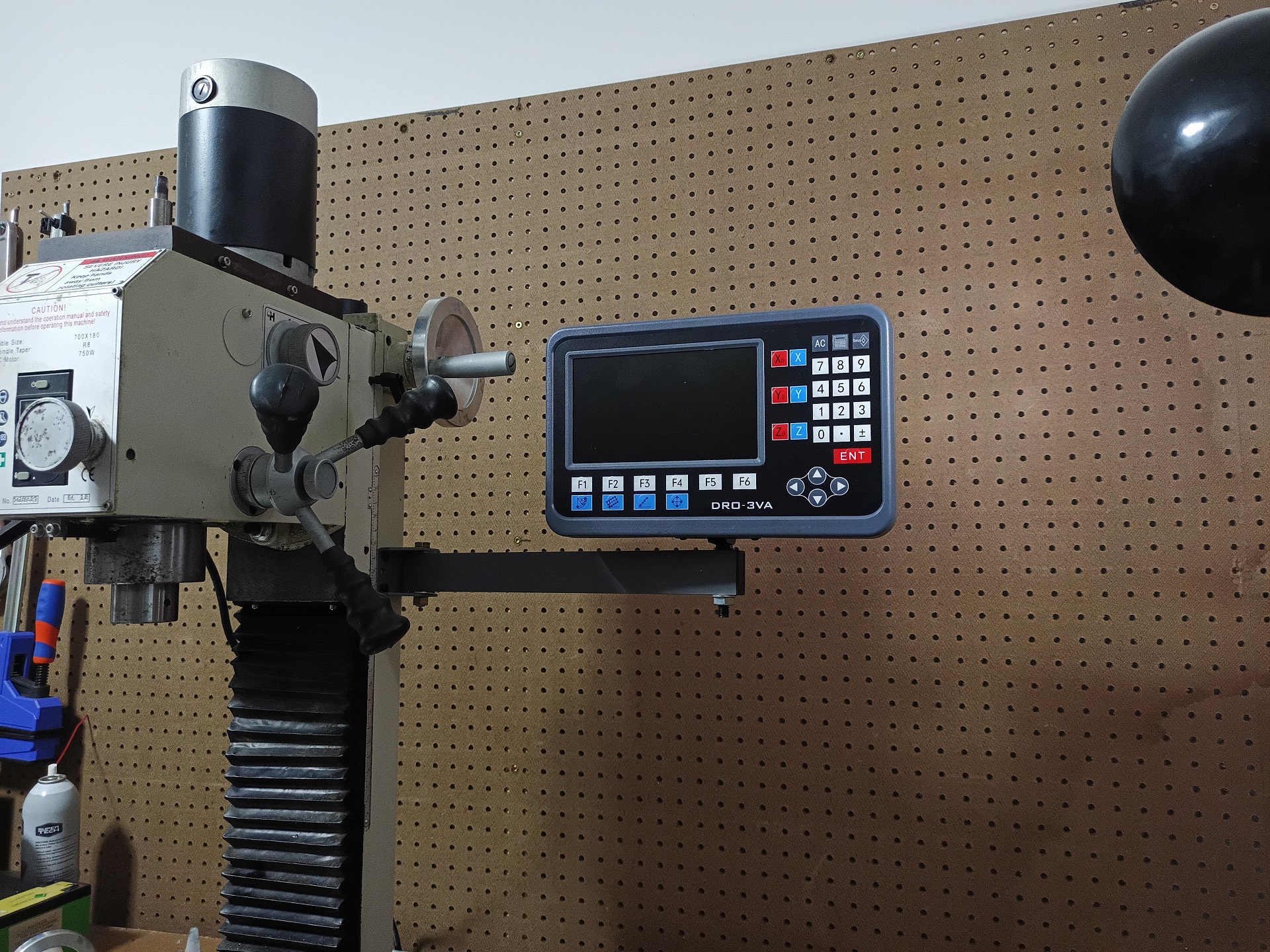
Nothing a little force on the drill press can’t accomplish. The arm mountnig bracket is also drilled and tapped into the column casting.
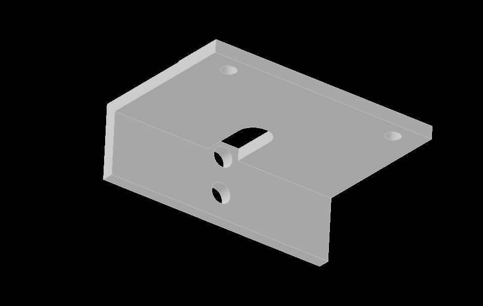
Now onto the Bracketry! Here is the proto-form of the X-axis slide bracket, made entirely to measured dimensions. The two mounting holes natively exist on the machine; they were to mount a little stopper/pointer at the center of the saddle. I’m just hijacking them to mount the readout slide.
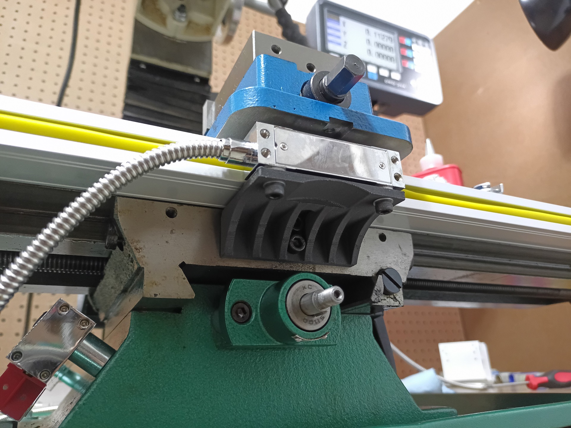
With a little more prodding and an afternoon print using carbon fiber filled nylon, the test fitup went very successfully! I didn’t really need to make any changes at all here. Notice the shim washers between the slide body and the bracket. I purchased washers of the right thickness to make up the thickness difference between the slide and the scale. I suppose they could have been “printed in” but I wanted the fine tuning.
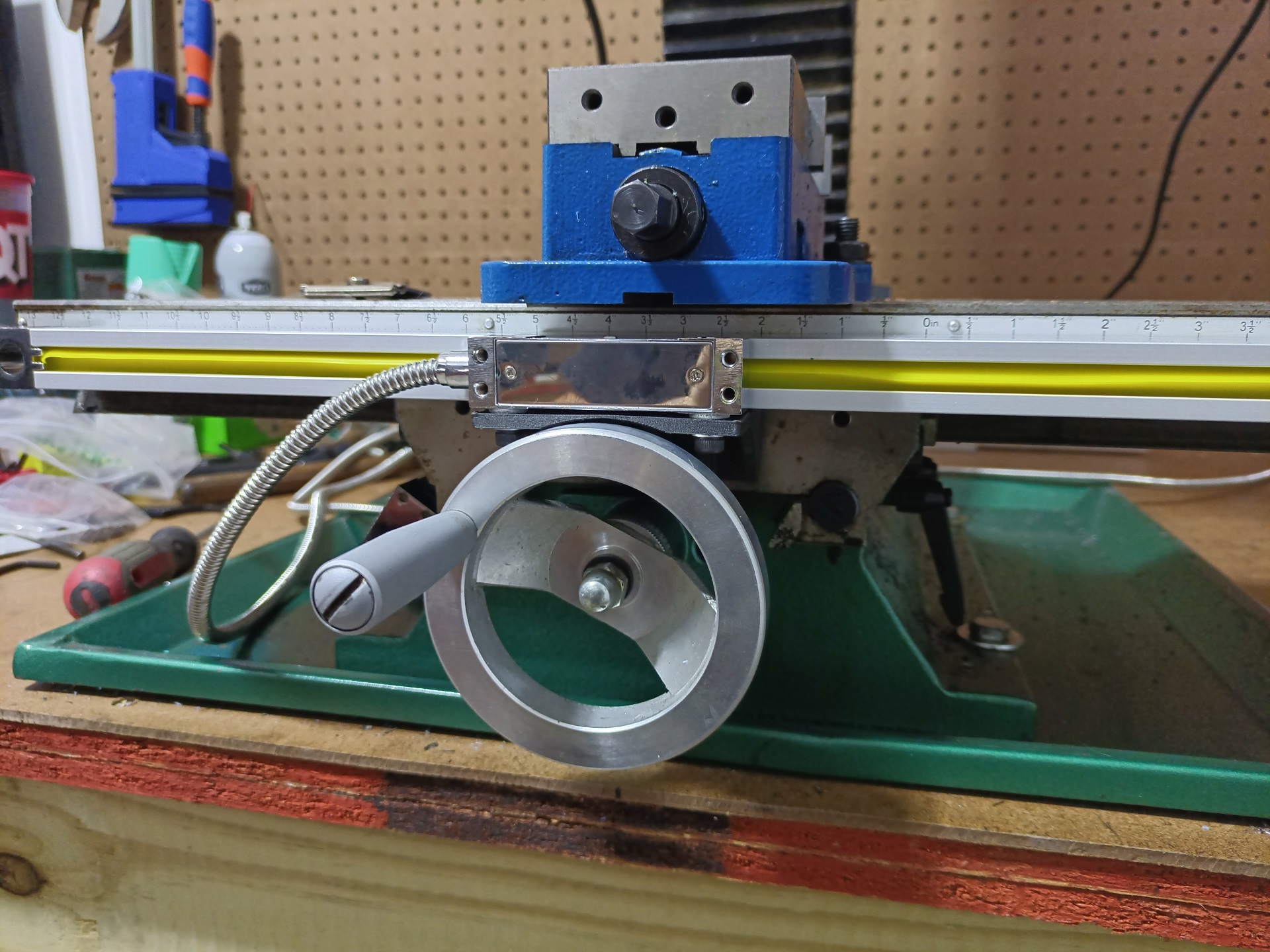
And here is the finished X-axis scale. The table is shown at its maximum travel towards me, so as promised, the slide overhangs the handle just a tiny bit, but is accommodate by the cutout in the Bracketry.
I later went back and made a second revision to add a little more rigidity. I remade this using the same CF Nylon, but added a post-print heat treat to increase its rigidity even more. I’m highly confident this is at least as good as a chintzy 2.5mm thick recycled beer can aluminum flap.
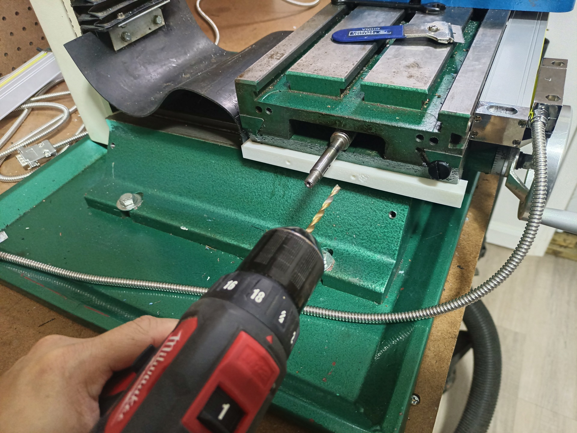
Next up, I used a jig to drill a similar set of spaced mounting holes into the saddle to accommodate the Y-axis slide.
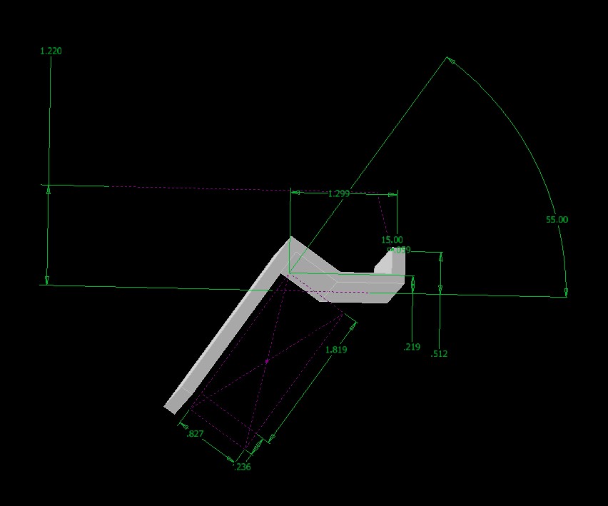
Now this thing was a lot more awkward to measure. The dimensions shown in the sketch are essentially the dimensions I took IRL with calipers, gauge/setup blocks, and so on. The bracket had to reach a little up and over the scale body, then drop down to hang the slide. I 3D printed this exact model to do visual checks, and ended up blasting out 2 revisions in PLA. This sounds like it might have taken forever, but with modern high-speeders like my Creality K2+, each Rev was really just like 20 minutes.
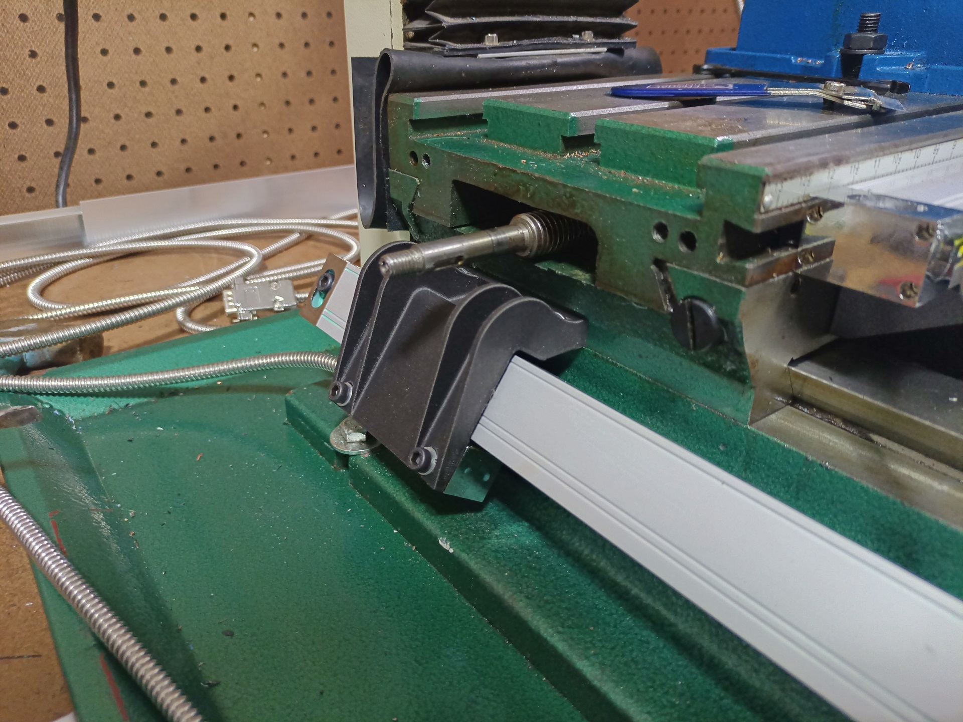
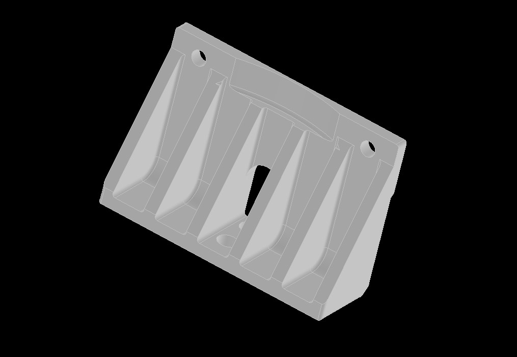
When I liked the fit, things got more serious and… a little weirder looking. This final revision was also made in carbon fiber filled nylon. It’s secured to the saddle with two screws wearing fat washers, and features four curving ribs to give it rigidity as it does the ol’ reacharound.
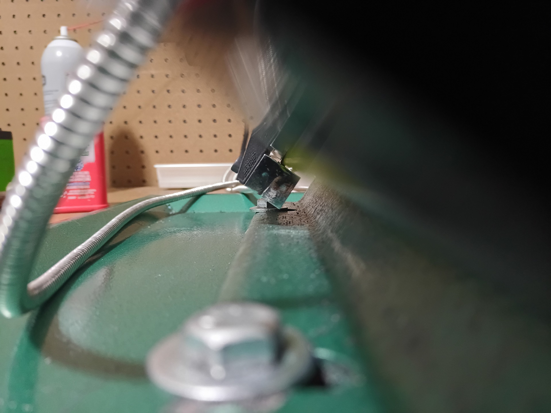
Very happy with how this turned out, as the slide barely clears everything yet remains fully aligned through its whole travel.
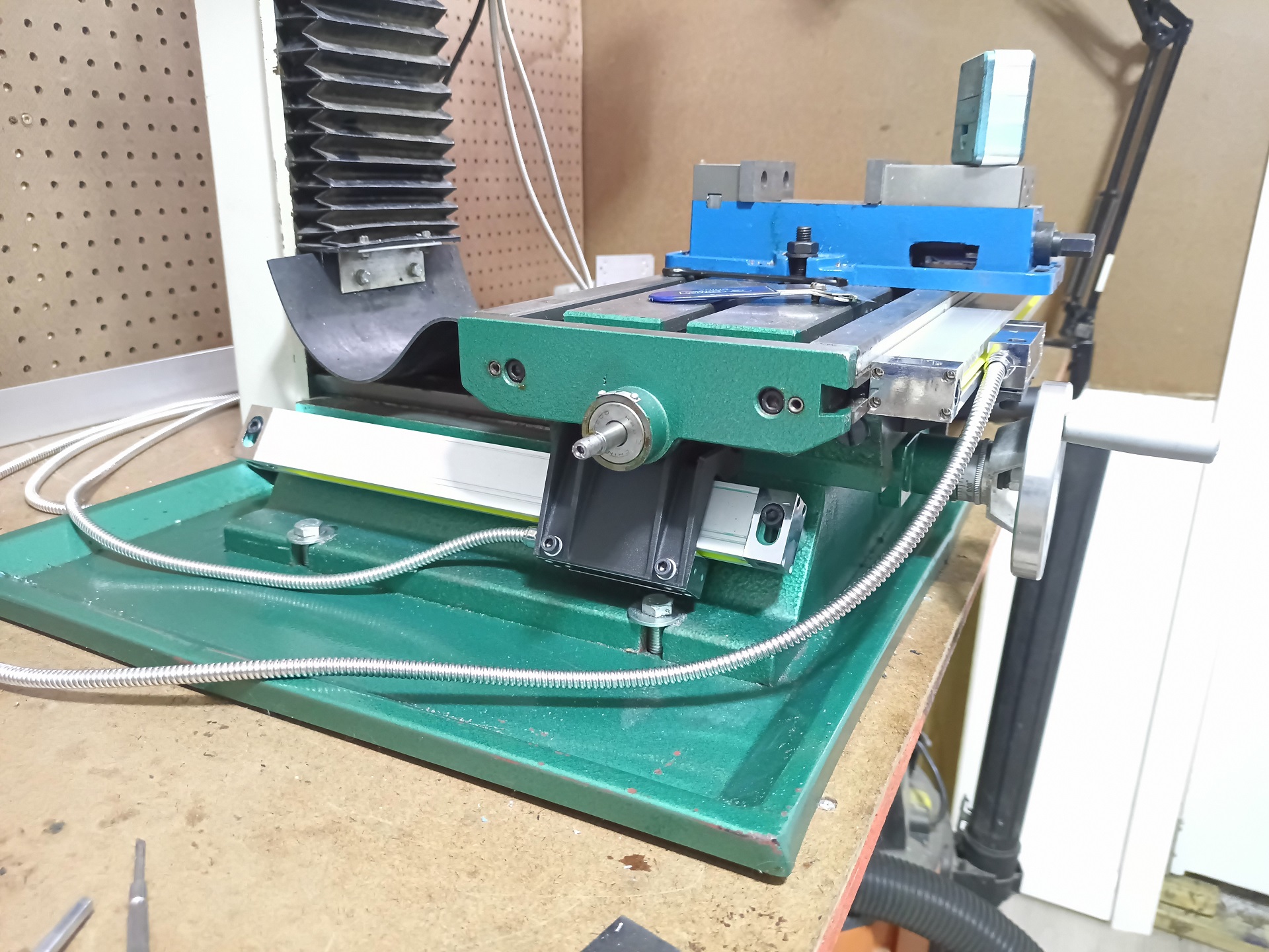
Not only that, but it was designed to accommodate the X-axis leadscrew and table endcaps. This is the farthest the table will crank that-a-away, and the leadscrew bearing bumps are just a few millimeters away from the Bracketry!
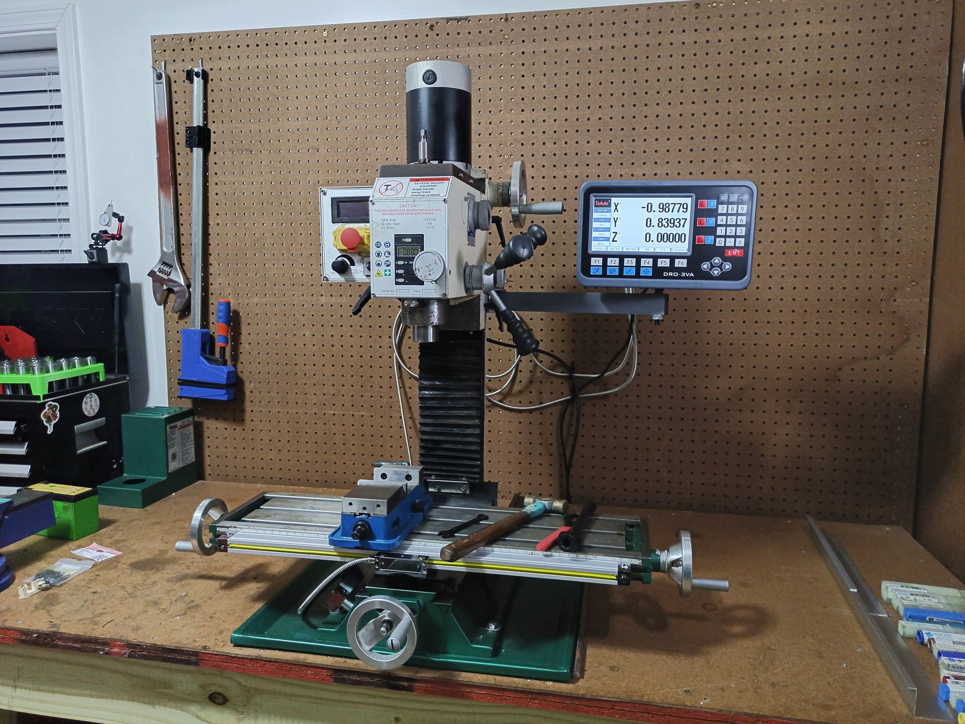
And there we have it. Suddenly this thing became 10 times as useful (or me 10 times as lazy). But at least it means I can bust out robot particulates even quicker!

i bought a mill

Yep, finally. After selling the Benchmaster, Master of Benches last January, I have finally picked up another one. The same points I made then still stand, really. The hangar isn’t wired up for 240 power (or meaningful amounts of power in general) yet, so having a Bridgeport would largely mean having a 2000 pound paperweight. I don’t believe in round column mill-drills. This meant waiting for one of the relatively few numbers of square/box column bench machines to show up on the used market… and those things keep their value.

I decided to sell on the Benchmaster because while it’s very cute and collectible, it was missing “modern mill” features I cared about. Mostly, that little thing didn’t have a quill. It was probably the most annoying thing about using it, since a drill chuck took up much of the Z axis travel and only the bed/knee feed was available. It’s patterned on American milling machines of the early 20th century, and most of them did not have quills or heads set up for Z travel either. Back then, drilling was considered much more of a separate operation from milling.

Luckily, a local antique machine collector responded to my sale ad. That’s really the best possible outcome for the thing, as it’s 100% a rock solid vintage machine that weighed probably thrice as much as a typical modern “mini mill” and would be at home with bulky cast iron friends of similar vintage!

Twenty ice ages later, I finally made a move when a Grizzly G0704 mid-sizer came up for sale locally at what I call “regret pricing”

Here it is, mounted to the heavy bench I built just for such a machine all the way back in November of 2023… and which had been used largely to pile unsorted tooling and cutters since then, because there’s been no mill.

This one came from middle Georgia, and the seller had bought it a few years ago to convert to a CNC mill. That’s a fairly common reason people buy the G0704, as it turns out, since it is a fairly basic machine that comes with a DC spindle motor, rudimentary controller, and no digital scales.

In the sale was also the entire CNC conversion kit; it’s a generic Chinese package with big stepper motors and pulleys/belts, and the Linux CNC computer to run it. And finally, a set of metric R8 collets and a kit of (carbide, as it turns out) endmills from 3mm to 12mm.

Basically, dude got in a bit over his head, ran out of time due to life obligations, and the project never materialized. Completely reasonable decision to sell it upriver to me, and I’m not gonna dunk on that. After all, “Got in over my head” is my M.O. and only because I don’t have life obligations. Above, we’re preparing to pull the thing out of his basement with a baby excavator (which was later used to sling load everything into Vantruck)

I want a baby excavator now. I mean, I always wanted one after seeing them in catalogs and on websites, but witnessing one in real life was another thing completely. This was a well constrained little day trip after all was settled.

When I got home, I craned the mill out of Vantruck’s bed onto my handcart, then set the crane up again inside the minishop to pluck it back off the handcart and onto the bench. I marked the holes in the base onto the bench when I pushed the thing to where I thought I liked it. Then I craned it up out of the way just a bit so I could drill the holes, and made the final bolted attachment. I’m not using the stand it came with, but I might turn it into something later on like a grinding/sanding station with wheels that lives in the hangar.

Well… now I have a mill on a bench. The big problem is, I had to kick much of my collection of mill tooling and other as-of-then unconstrained tooling and cutters off that bench onto the lathe bench. I now was forced to finally do something about organizing all that!

I made another Pegwall using called-up reserve materials, purchased from the first time around last year. This one is just a half size, 44 inches wide, to fill the space up to the “bedroom closet” which is still kind of an unallocated space (The floor drill press migrated into the hangar as part of this effort).

The Huot dispenser drawers I bought long ago were emptied out and repurposed. I resold as packs/sets basically all of the taps and endmills in them, as the majority were sizes I already owned in some way. I kept only a handful of duplicates and ones I didn’t own yet (like thread-forming taps).

Basically I just relabeled by hand the drawers I needed based on the sizes of tooling I owned. I am not a job shop, I don’t need 3 different drawers each of Plug/Taper/Bottoming type taps, per size. Just the sizes I need to use with some spare empty spots for future expansion.

Somehow I had collected enough 1/2″ reduced-shank (Silver & Deming) drills to make a full 33/64″ to 1″ set by 1/64″ increments… with a bunch to spare, and several larger than 1″ drills! I decided to make wood block organizers like I’ve seen a bunch of times. Some “nice” wood from Home Depot (I’m not even sure what wood it is, besides Nicer Than The Usual 2×2) and some marking and drilling later, and they were done.

The hanger brackets attached to them are for use with plastic organizer bins. I just screwed 2 of them onto each drill bit forest.

One can think of this as kind of the “drilling and tapping” wall. The tooling I had enough of to be annoying, but not enough of to make a comprehensive organized drawer in a tool chest, all got homes in little labeled plastic bins. Drills, taps, countersinks, counterbores, and miscellaneous hole-making implements like my stash of spot weld cutters, and so on all live here. There’s plenty of space on this pegwall for things to grow and evolve, even though it looks a bit barren right now.

The little pink drawer block contains Dremel accessories, because why be boring and buy just the black drawers!?

Of course, with a labeling and organizing spree comes the way I prefer to label and organize things.

I decided to get a new set of “the basics” for the mill just to make sure I have everything I needed besides cutters. Like, I’ve had an odd edge finder here and there, and lost my DTI many moons ago (it’s probably still in a tote or basket somewhere, and I’ll find it immediately after sorting stuff).

This was a fun chance to see if anyone else has invented machine shop goodies too. I found this R8 collet rack that would fit all the metric and inch ones I had accrued. There were more “creative” designs for racks and holders as well, but I’m more a simplicity guy. Some times, people going ham making 3D printed organizers and shadowboxes for everything feels more like making a set for a Youtube channel – which, quite honestly, many of those are.

A long time ago, I designed up a small tray to hold something (it was in the Robot Trap House CAD folder) and so I just changed some dimensions and pattern multiples to turn it into general purpose endmill and cutter holders.

Thoughts about making up a Gridfinity system or something did cross my mind, but again… making it useful for me first. I wasn’t in the mood to plan out that far.

As long as it fills up my toolbox drawers and I can scribble on it. There’s an additional tray set, miniaturized, on the top deck to hold things like the edge finders. Rapid access up top, more esoteric as we move lower. The next drawer under this one currently just has a R8 drill chuck and fly cutter/face mill in it, but it’ll probably be where the R8 tooling will live.

So now the only thing the mill is missing is digital scales, which I’ll attend to at some point. For now, driving it by eyesight and Sharpie scratch marks is sufficient. At least I can readily shave parts down, make keyways and motor shaft flats, and more complex bolt patterns again, and now with a quill and Z feed too!

Funny enough, the very first job I needed the mill for didn’t strictly require a mill but the rigid, dial-able setup made things much easier. I wonder what it is…