Susquehanna Boxcar Never Dies: Reviving This Stale Meme with 30Haul’s Old Drivetrain!

Good ol’ Susquehanna Boxcar.

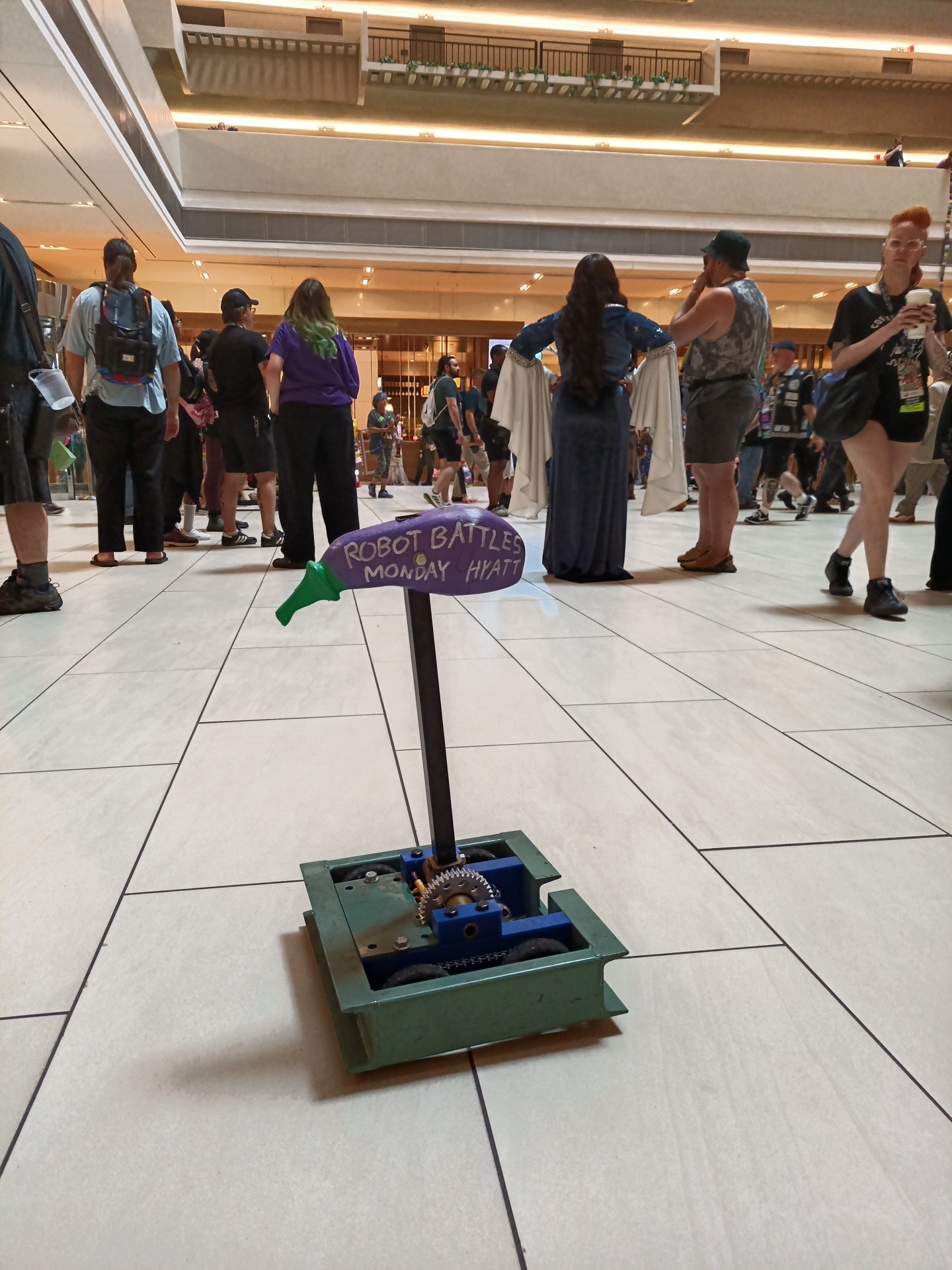
What started as a quick-build meme using whatever I had dug out of my (then, in late 2021, still not yet unpacked) totes full of motors turned into… something that just kept evolving and getting funnier. After doing suspiciously well at Motorama 2022 using only surplus inkjet printer head motors for drive, it got switched to brushless power in 2023 and then kept on doing suspiciously well at Dragon Con.

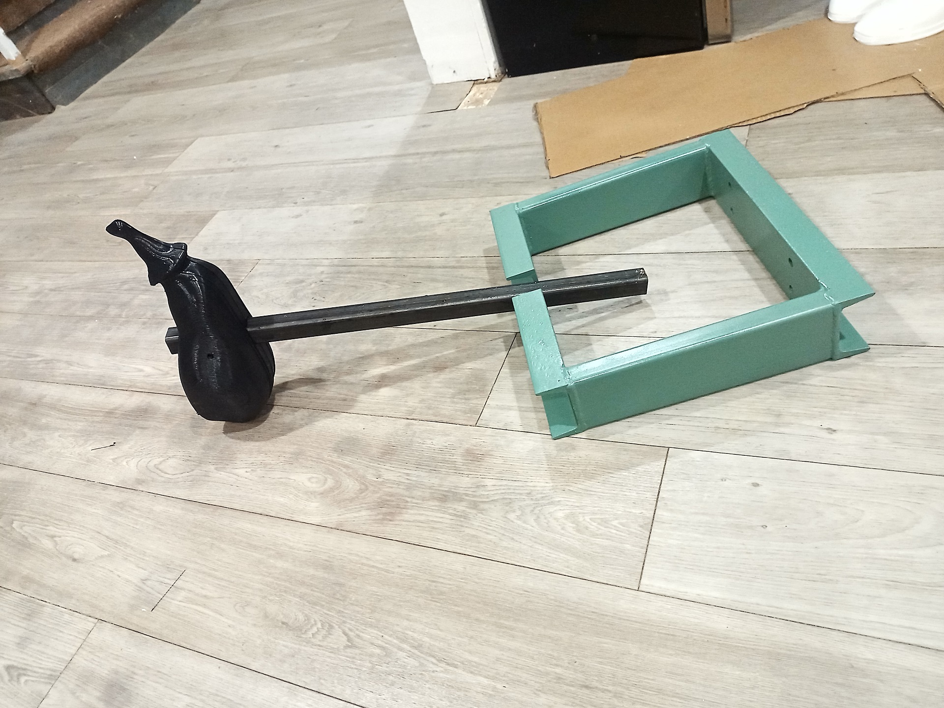
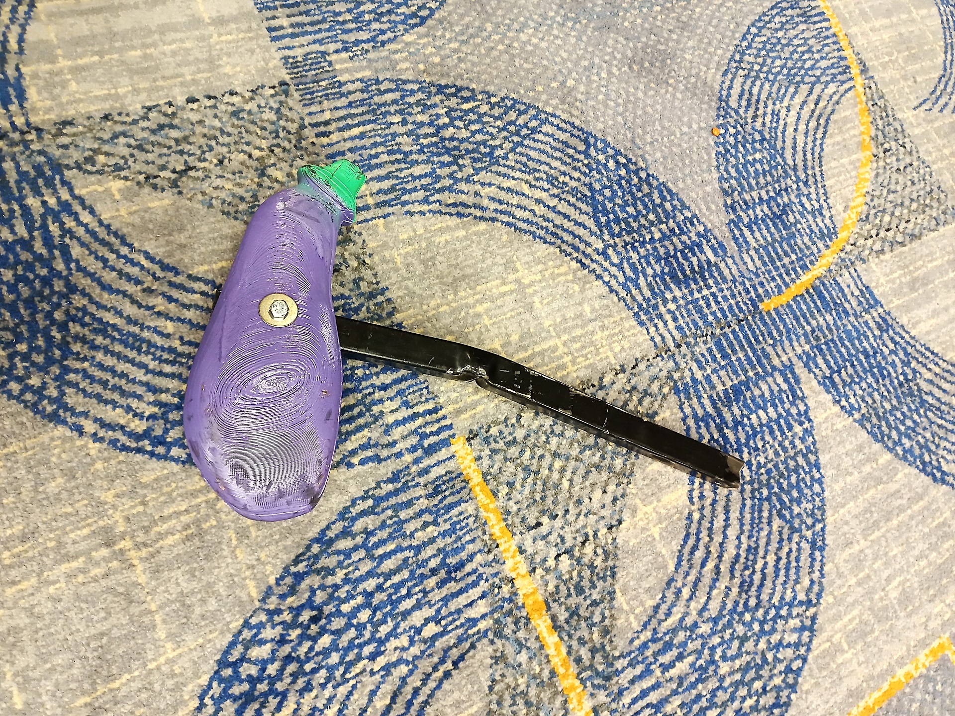
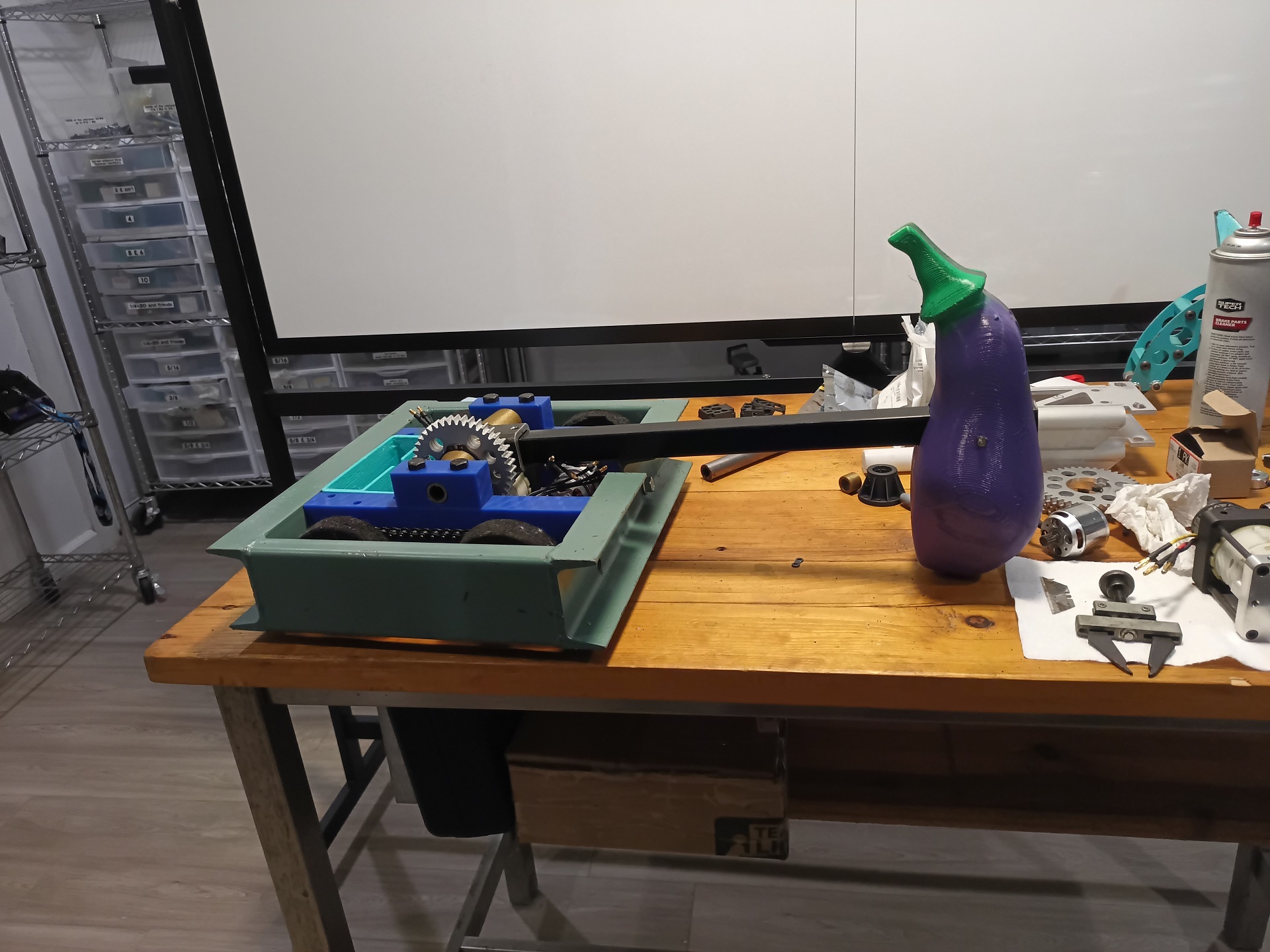
Zip tying a Taro root to the thing in 2022 was funny, but the Papaya of Redemption really kicked off the wave of “Boxcar must always use a quasi-phallic vegetable, or an analogue of one, as a weapon”

Always having been a hacked-together build, by 2024 the thing was really showing its technical debt. It was tacky to service, which cost me fights at both of those events. Much like old Uberclocker builds of yore, I didn’t really care how it went together as long as it did. And so, after burning out 2 of the drive motors at Dragon Con 2024, I decided you know what? It’s time to SPEND MONEY on it. (I mean, ignore the fact that I spent money on it from the start even though I said I wasn’t going to, as if the first thing I did after declaring I wasn’t going to spend money on it was ordering a bunch of UHMW strips from McMaster)

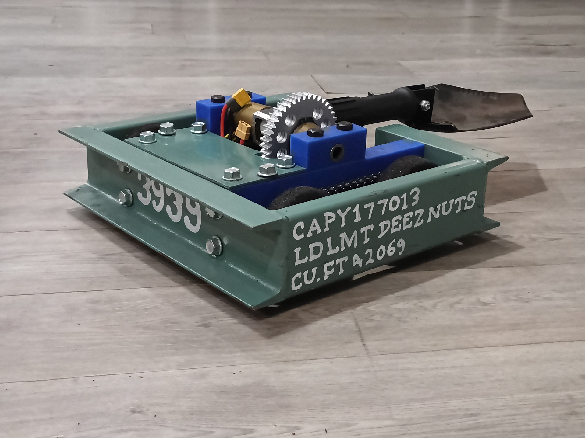
a picture of robort

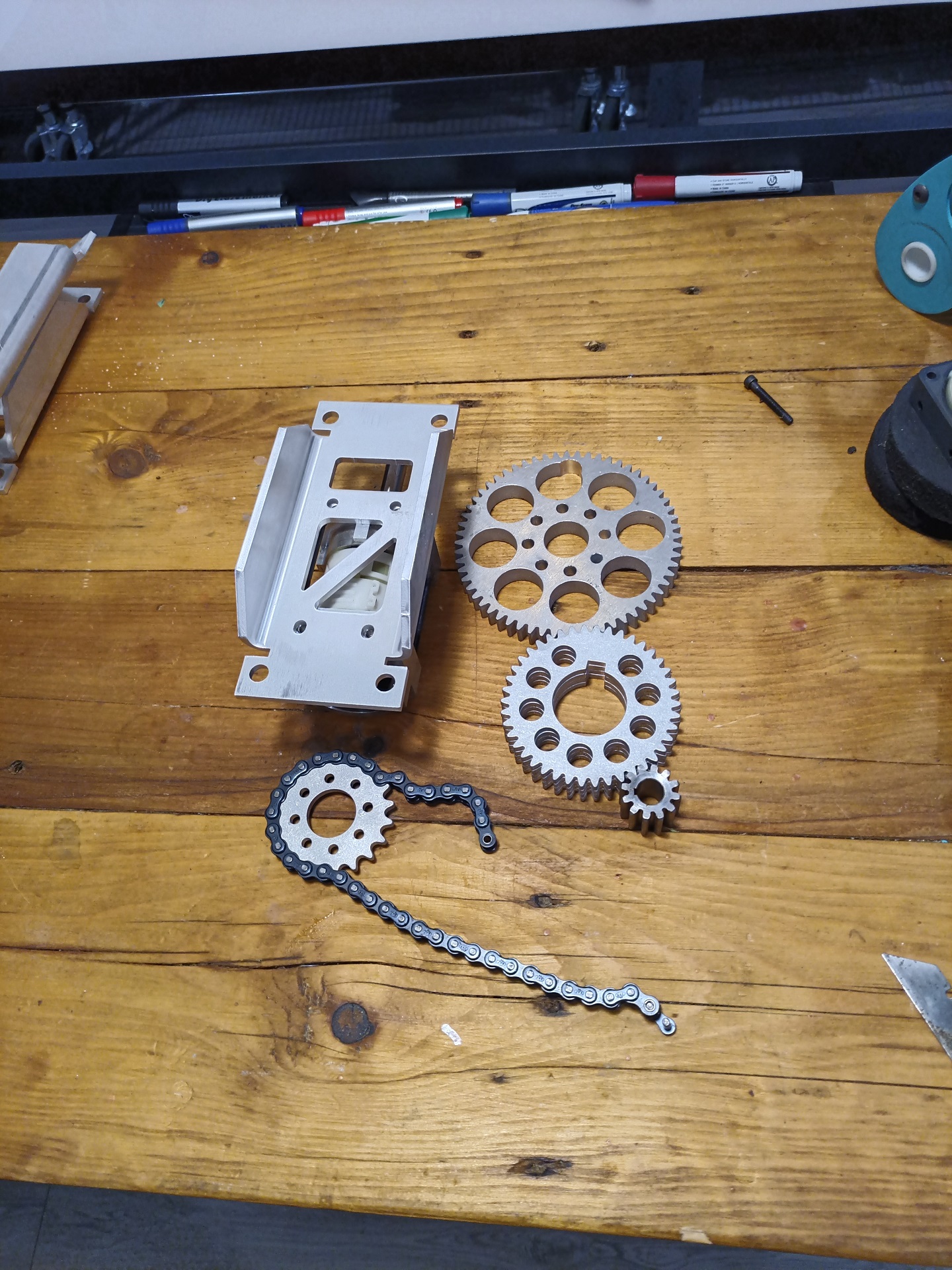
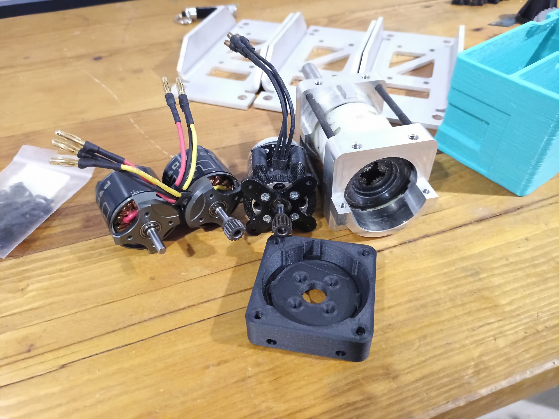
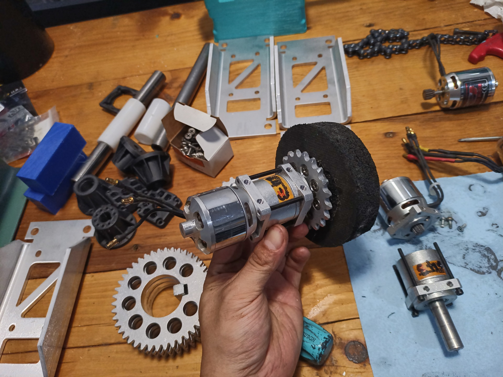
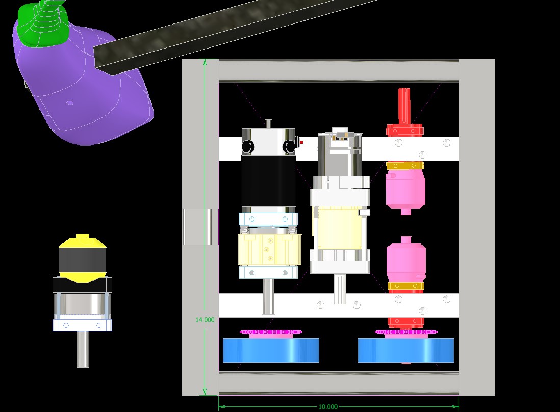
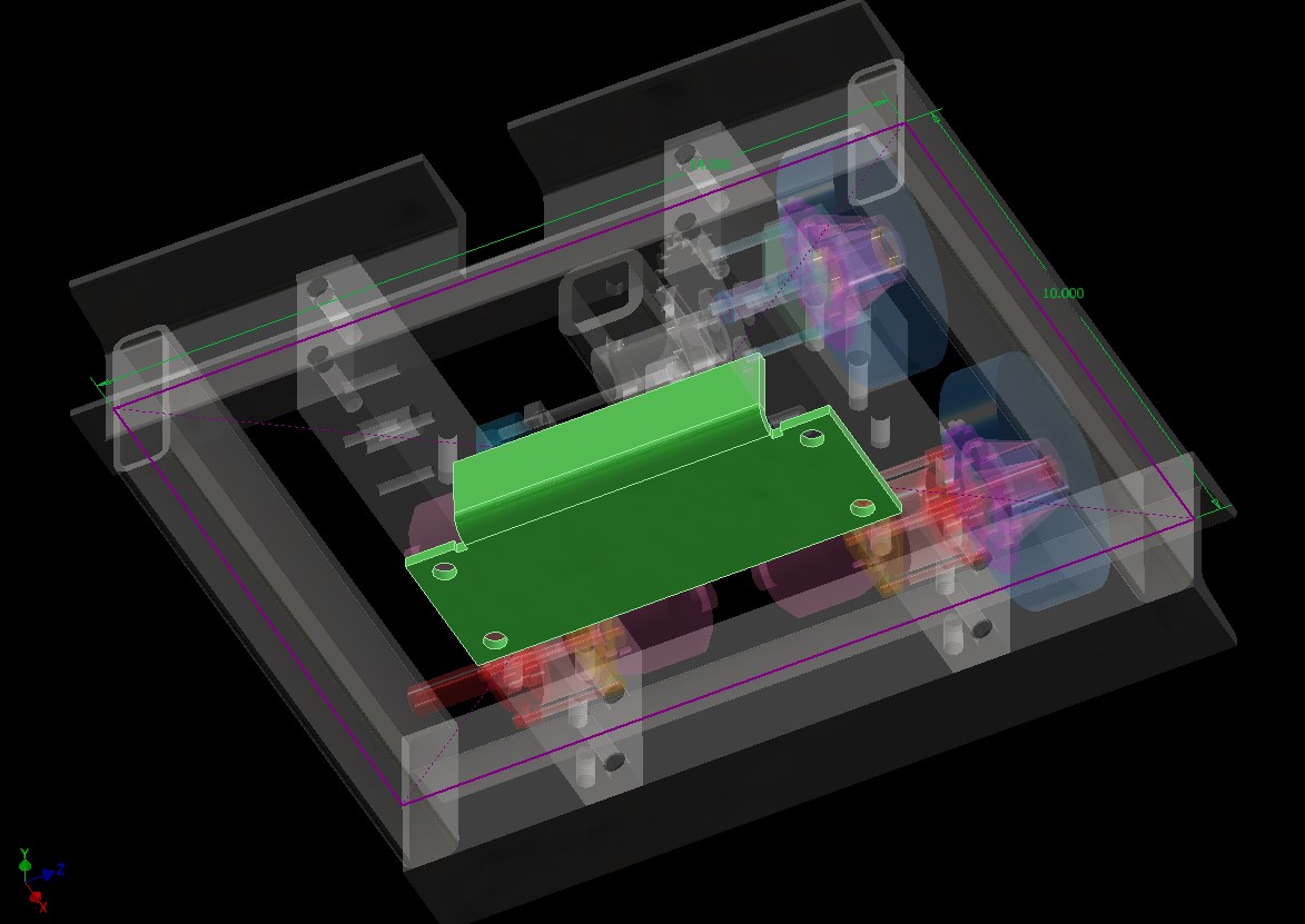
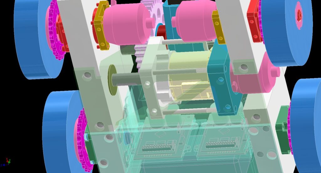
First order of business is to throw a bunch of random motors into CAD. The idea was to reuse parts I already own from 30Haul – I’ve owned a tote of the last 30haul’s wreckage ever since its final NHRL event in 2021. I sold the chassis parts and some drive parts to various people – some of whom have even managed to vaguely rebuild and remix it. I retained much of the intact drivetrain consisting of 42mm HobbyKing SK3 motors zipped to P61 gearboxes, as well as the gears and sprocketry that made up the lifter.

A couple of other wildcard motors also made it into this bucket of brain pressure washing grime. One thing I wanted to do was upgrade the hammer/lifter/eggplanter motor. The bot used a Harbor Freight 18V drill gearbox that I hot-modded (“Harbor Freight 68239 LS Swapped.iam”) with a 3536 size outrunner motor. While it “worked”, it had durability issues from the much greater torque input the motor was capable of; primarily, the age-old robot community drill motor hack to secure the drill’s clutch ring kept blowing out because the casing would actually flex too much.

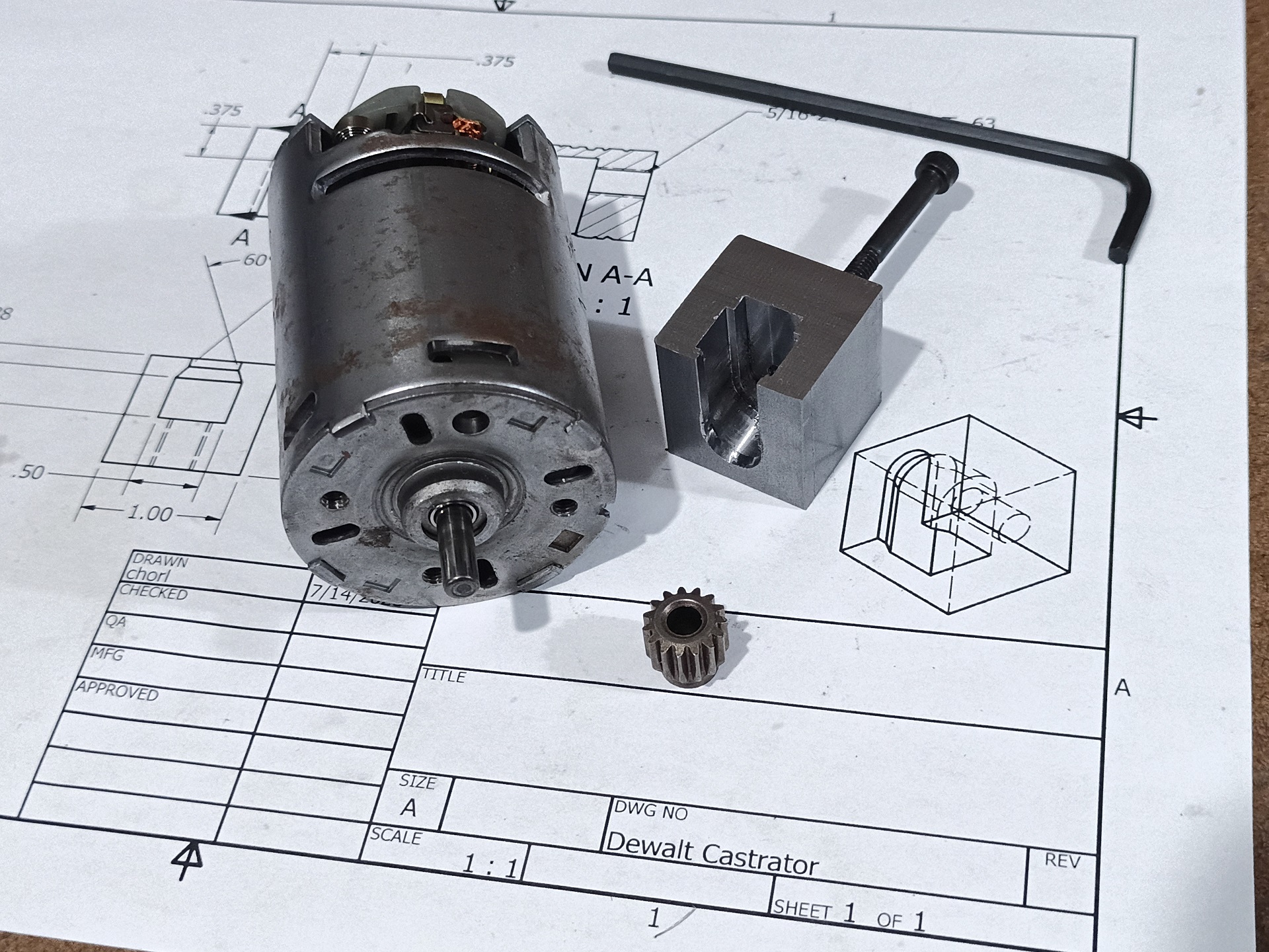
So there’s some surprising motors from the past in there. One of them was sizing up a BaneBots P80 – that model I put together for old 30Haul ages ago. Another one is Overhaul 2’s never-implemented Banebots P80 based shifter gearbox, a design I ripped off from the DeWalt 3-speed gearbox next to it that forms the foundation of the DeWut motor. All three are of the same size class, 2.5 inch across size, and it was more of a matter of what actually fits lengthwise.

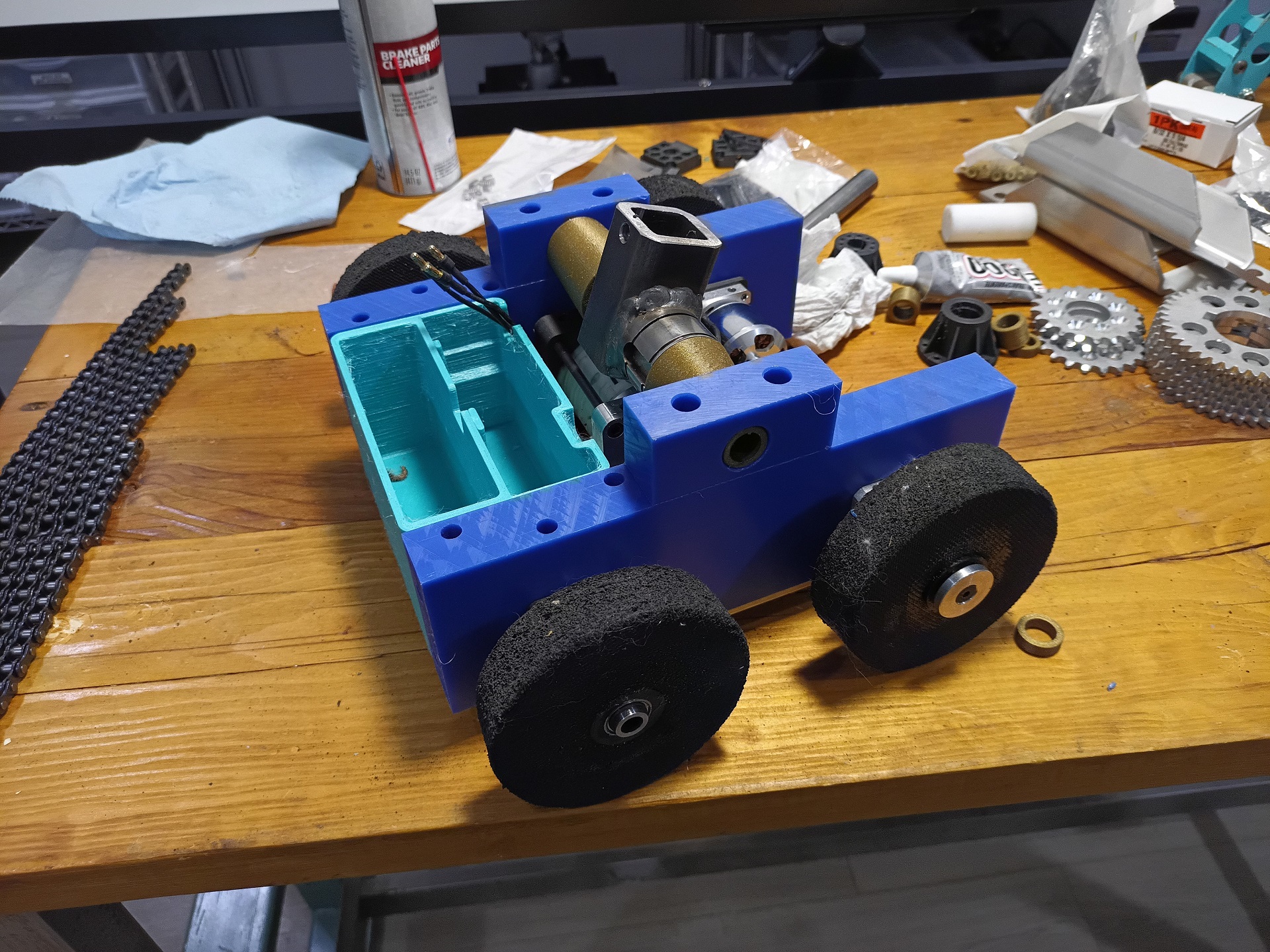
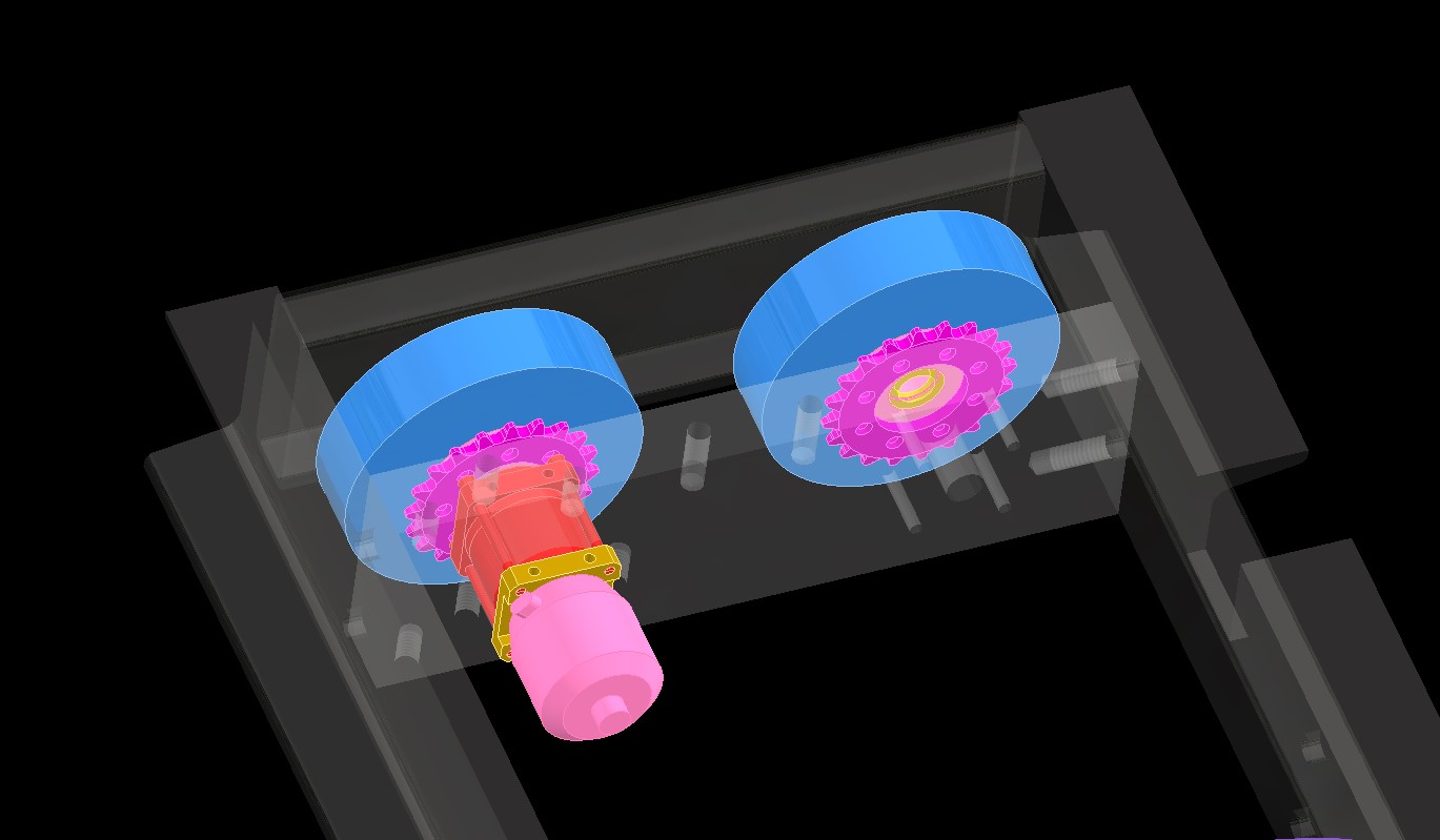
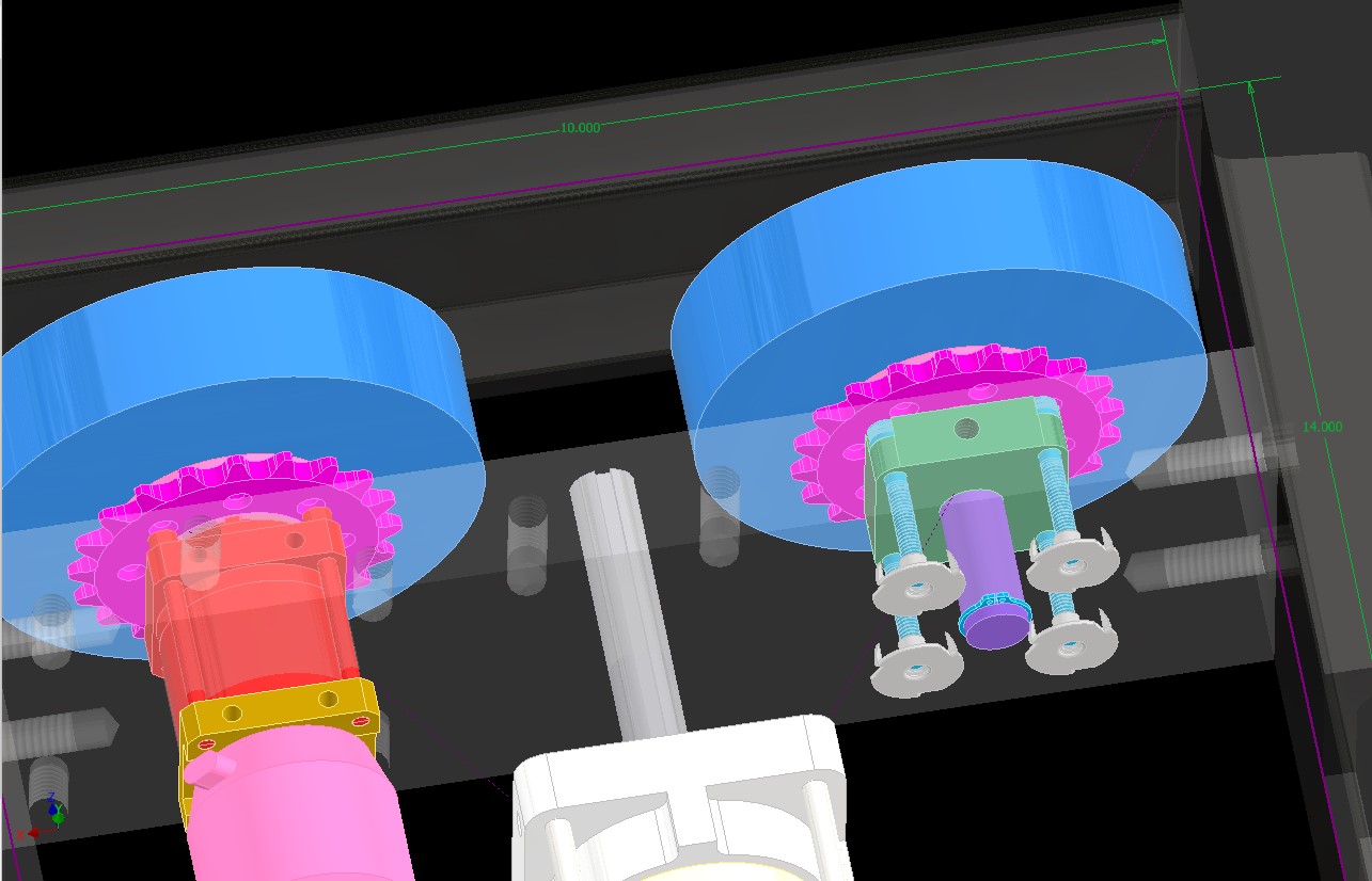
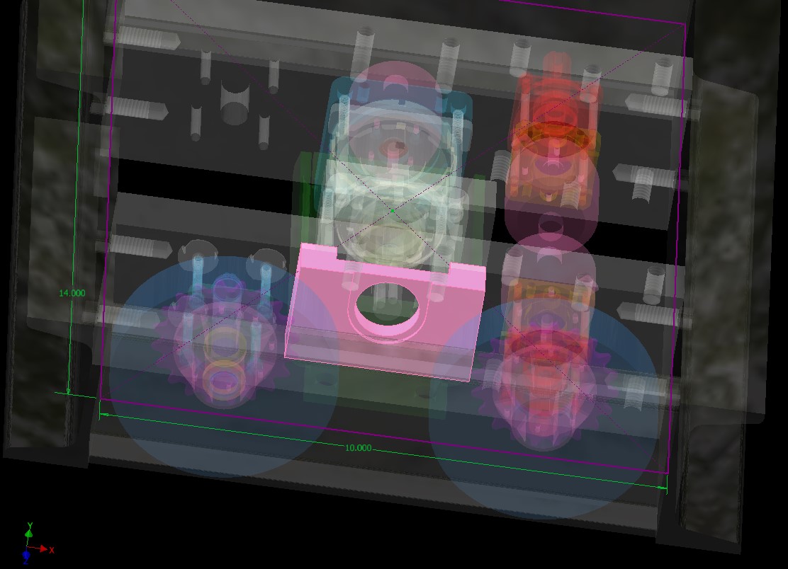
One thing that was pretty decisive was the drive motors, which I decided will be 30haul’s drive gearboxes. So while I was still mullling the lifter/hammer motor decision, I did some starting detail design on the drive. The layout will no longer be a motor geared to each wheel, but just a pretty regular direct drive rear and chain drive front.

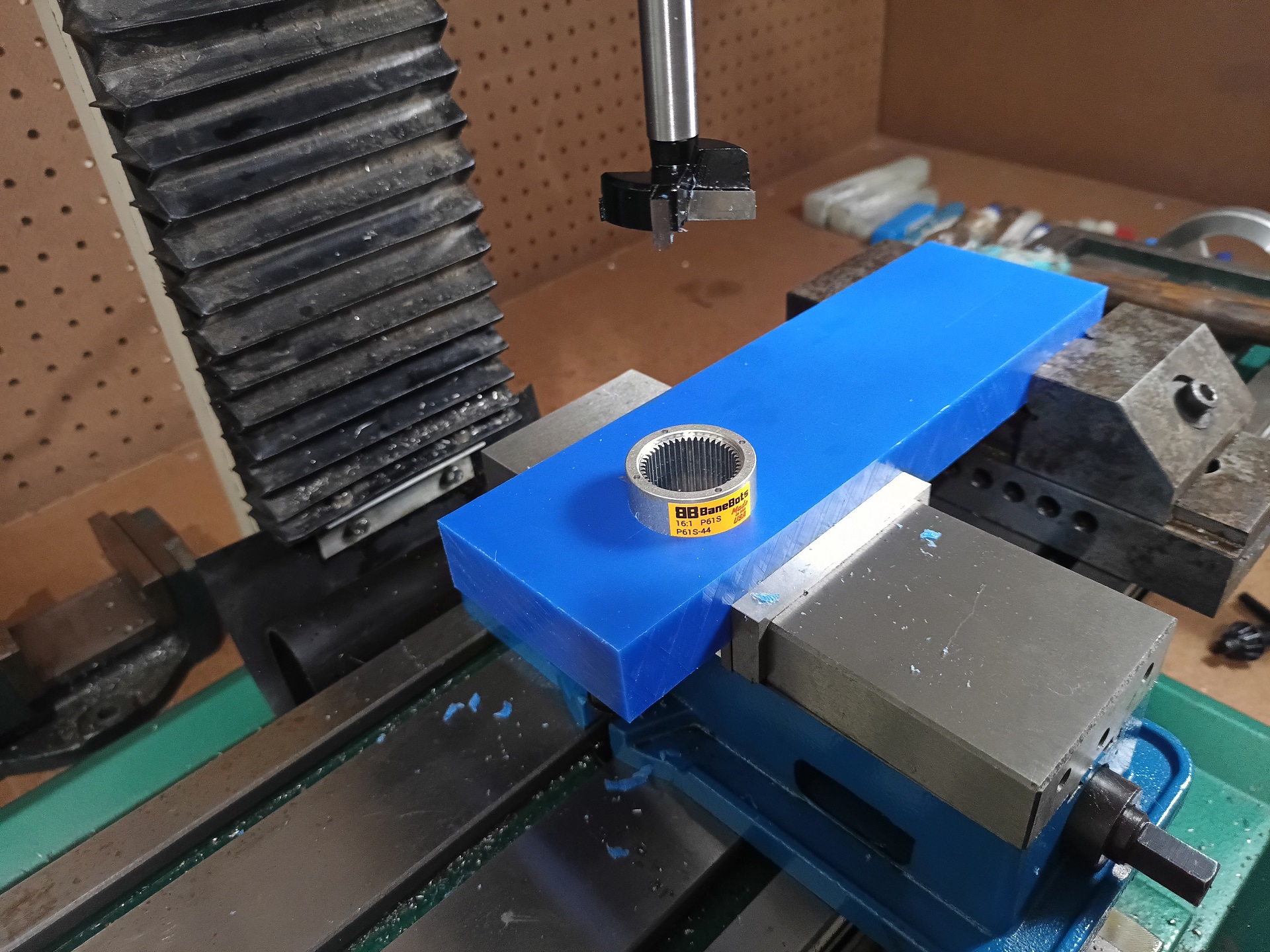
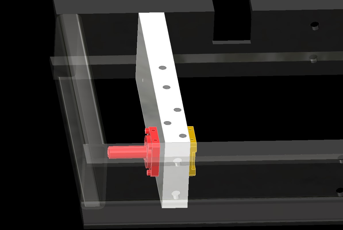
The real innovation here is just that I am copying some homework from NHRL bots that have done it this way, and fully embedding the drive gearbox into the thick UHMW frame rail. It’s just drilling a big center hole and four tie rod thru-holes and trapping the gearbox inside. For the front, I’m making a “fake P61” block that uses the same bolt pattern so I can recycle the drilling template.

The wheels modeled are basically the same cut up gum rubber foam I’ve come to favor, on 3D printed hubs, to which plate-cut sprockets are attached. It’s a divergence from the “gearhubs” of the previous iteration, but not by much.

The fake P60 will be tied to the frame with some tee nuts for wood, another bit of a throwback for me. UHMW is easily shaped by woodworking tools, so it was one of my favorite (and only) robot materials back in the day.

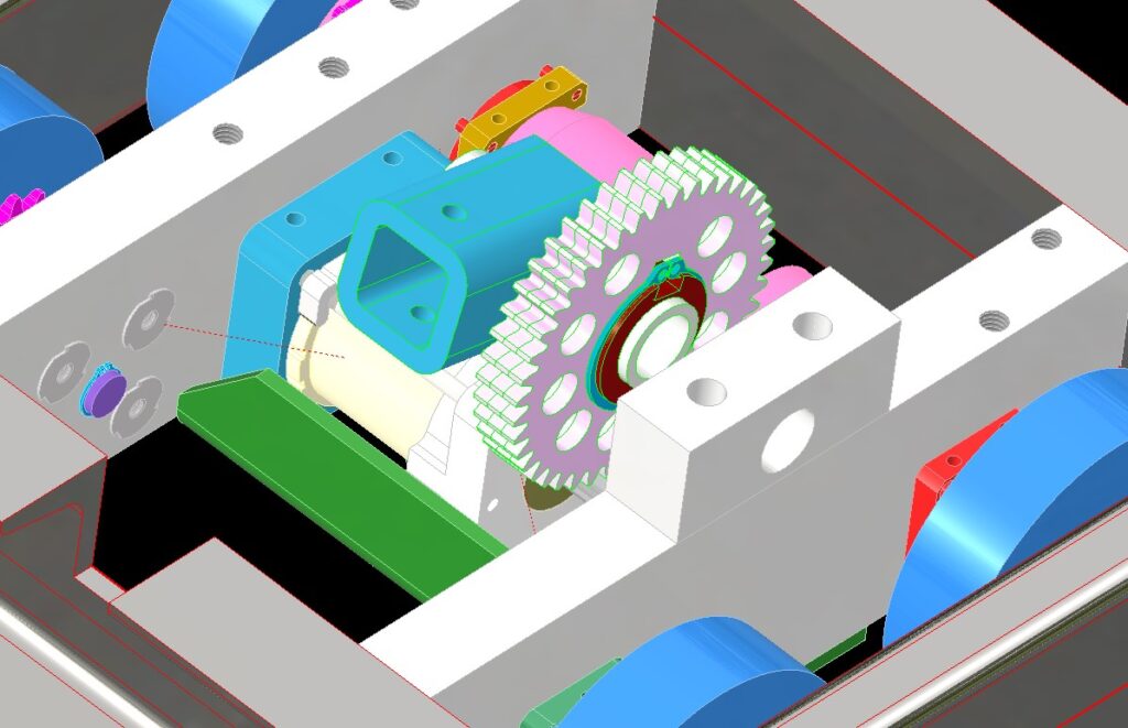
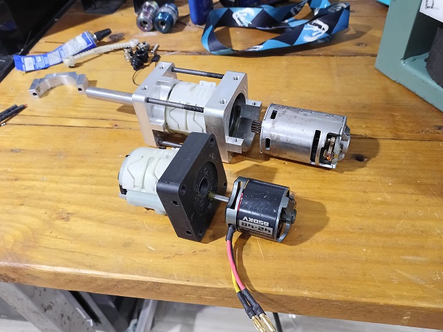
Around this time was when the real innovation started. Namely, I decided to give a brushless DeWut swap a try. Most because this was the only way I could fit it, and also because I wanted a quick and easy to switch between “hammer” (fast gear ratio) and “lifter” (slow gear ratio).

If you’ve been in my circle for a long time, you’ve probably heard “Brushless DeWut” thrown around forever now. With modern cordless drills all having become “unibody” i.e. there’s just no more separate gearbox and motor combo inside the plastic shell, making a drive motor conversion is a lot more involved. And with the robot drive market having moved towards bespoke solutions instead of repurposing industrial and commercial motors (*shakes cane*) there was simply no market-based incentive. I’ve bought 4-5 models of brushless drill over the past few years and they all follow similar thought patterns.

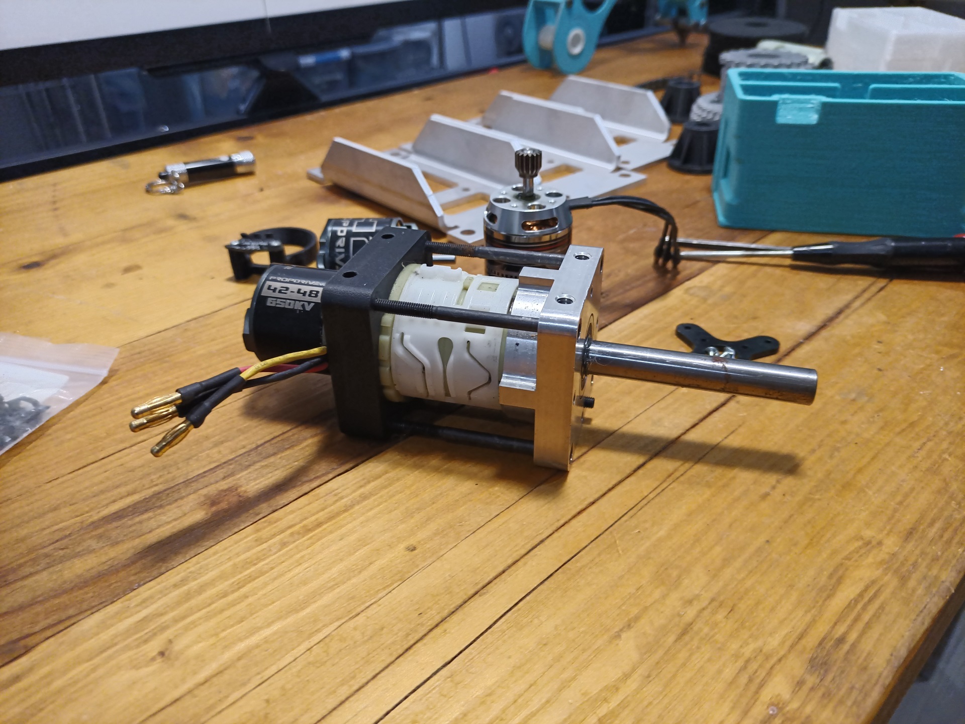
All this entails, though, is stuffing a 42mm outrunner motor into the back side of the existing DeWut conversion.

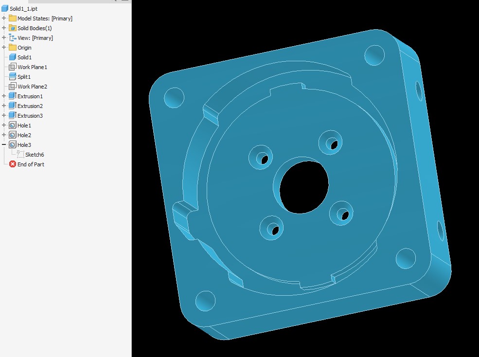
Nothing substantially exciting to be seen! I took the original DeWut model from 2011 or something and just cut the back of it off, then made a motor mounting face. The whole thing will be a 3D print using carbon fiber filled nylon, probably with a few laps of carbon fiber thrown in using my Markforged machines, to keep it rigid in the barrel section.

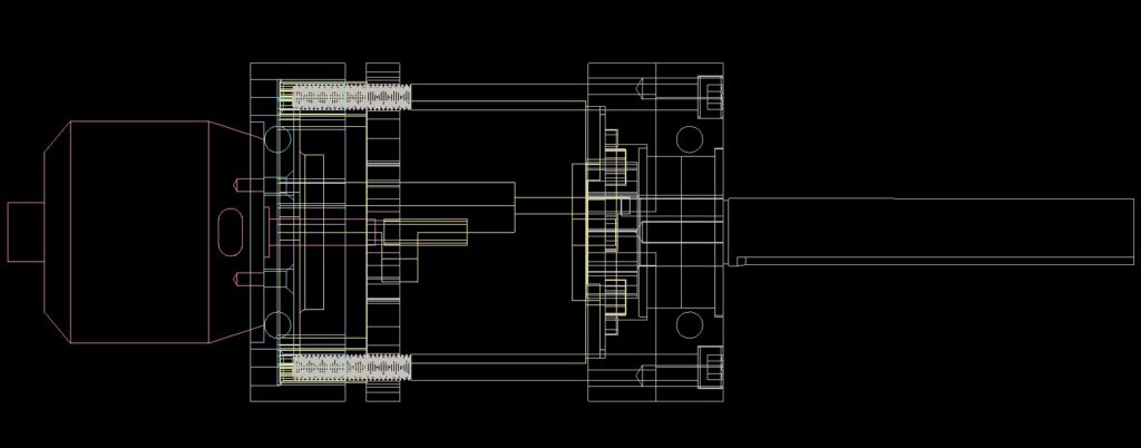
Here’s a cross section look through the assembly. A 42mm size motor has a 5mm shaft just like the DeWalt motors did, with a pressed pinion. I didn’t want to have to cut or modify the motor shaft, so the depth of the motor mounting face was set by measuring where the motor shaft reached the gearbox first stage, plus a bit of clearance.

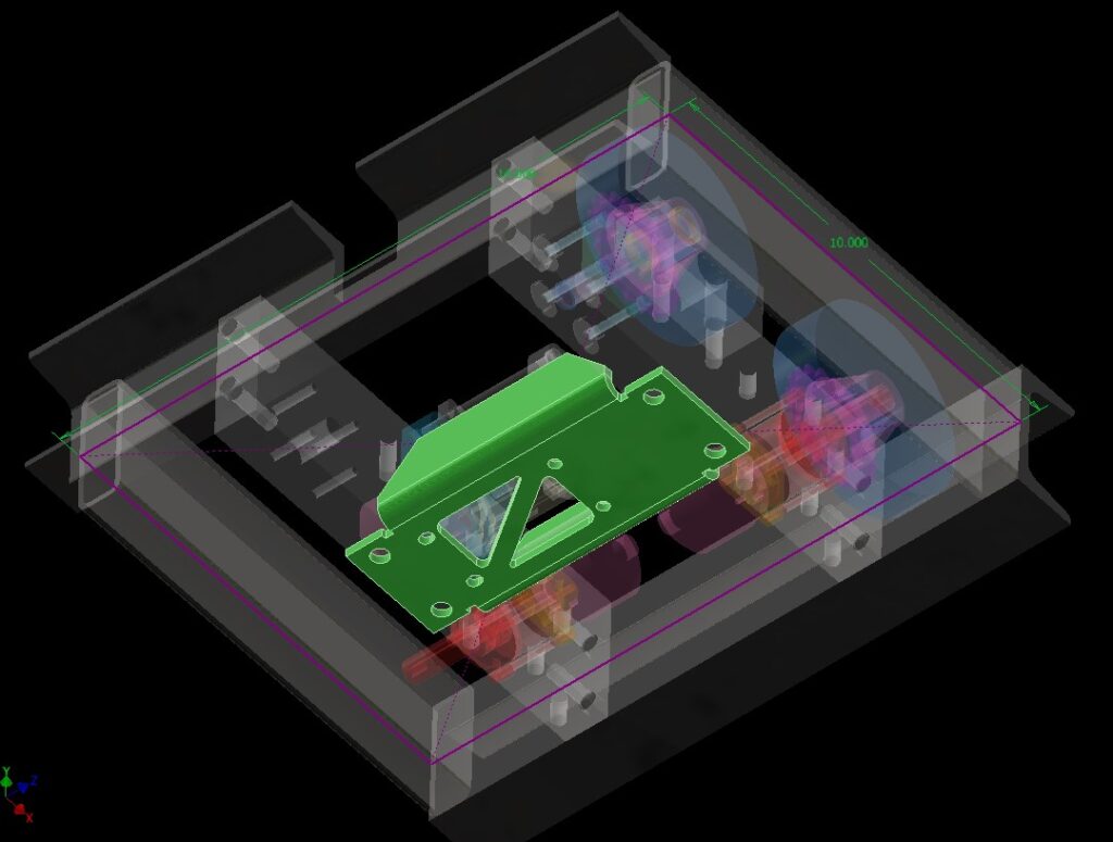
From here, the design cooked pretty fast. I wanted the weapon motor to be serviceable without taking the entirety of everything apart like last time, so I decided on a bottom-drop sheet metal bracket. By “Sheet Metal” I really mean 3/16″ thick aluminum. At this point in time, with the likes of SendCutSend and OSHCut offering express and precise sheet metal service (This message brought to you by neither of them, by the way, I just prolifically use both) there’s just no more excuses.

Historically I’ve been turned off by sheet metal assembly techniques because the Chinese guy running the press or brake machine was me. Very rarely could I actually manage two parallel bends or get anything to line up, much less get the bend radius right (Ever notice that your average cheap sheet metal combo machine has all sharp dies instead of radiused, and assume you’re working with gauges thin enough where that just about doesn’t matter?)

But I’ve made plenty of assemblies for other people now where a half dozen large bent and formed parts come together with almost dowel-pin precision. It was time to make some for myself for once!

“Draw the rest of the fucking bracket” happened, but really all that is is adding the mounting features of the DeWut.

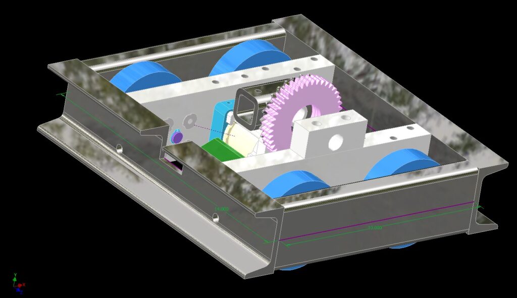
To allow for a bottom drop while providing support for the distal end of the motor output shaft, I just made a quick “pillow block” that will live with the bracket and holds two flanged ball bearings.

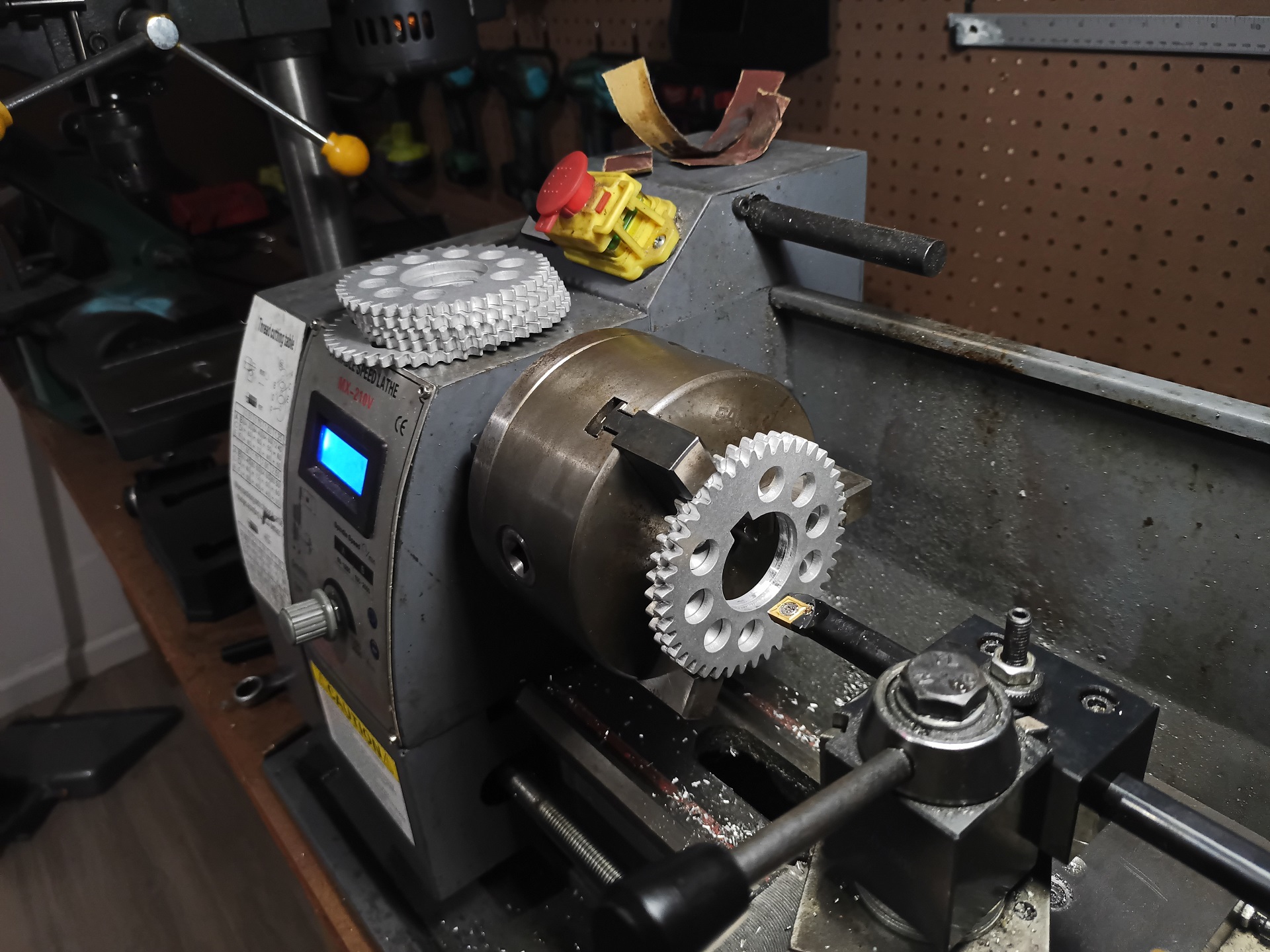
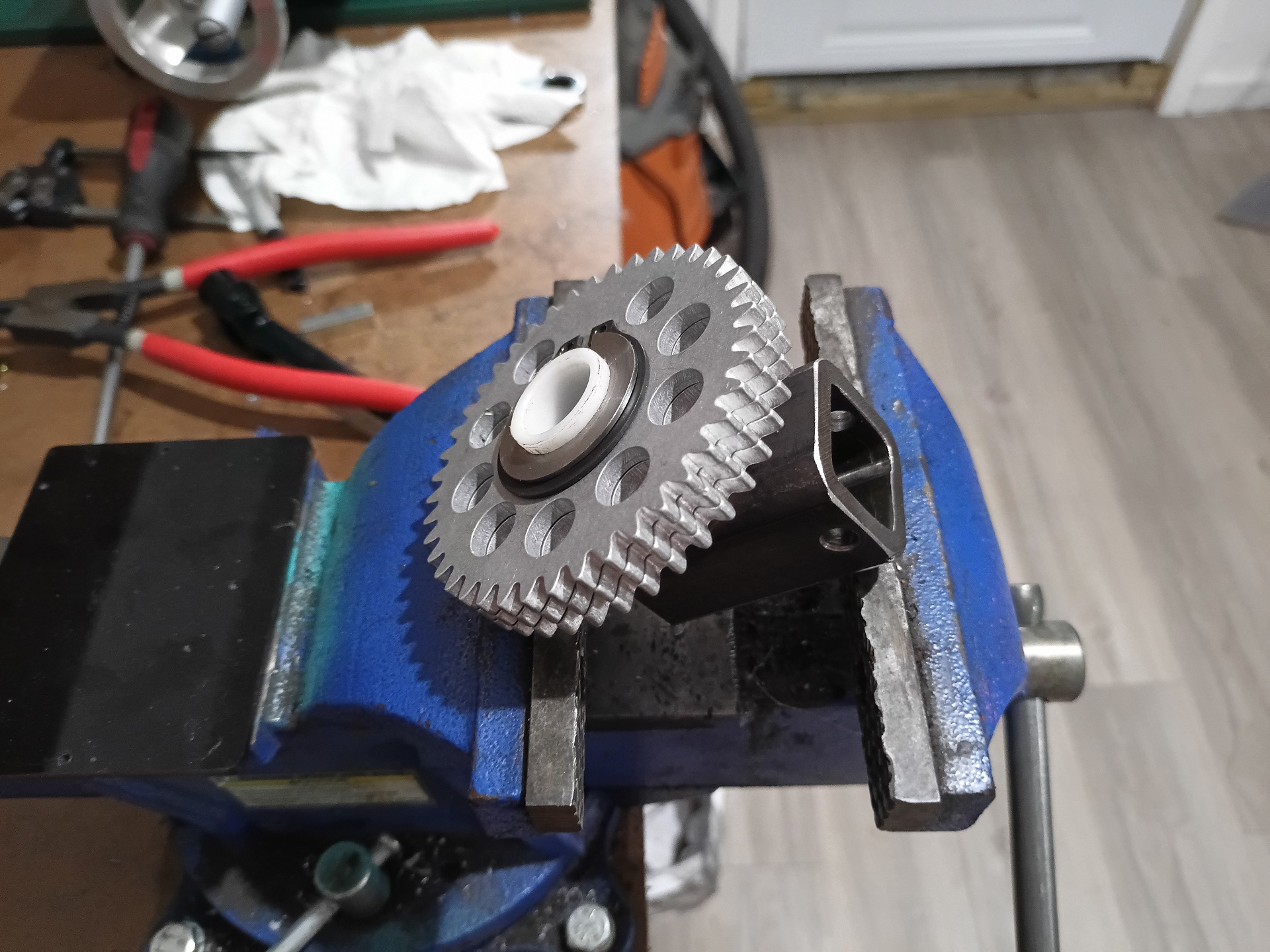
The quick drop service basically implied moving to a gear drive instead of chain drive. I whipped up another set of 12 DP spur gears, much like what I’d use in Uberclocker and 30Hauls of yore. The difference is this time, I’m doing them “laminated” style from the same 3/16″ aluminum that will form the motor bracket! This saves some cost using those online services since there’s fewer material setups.

To compensate for the slightly weaker nature of a bunch of thinner gears in a trenchcoat (with their unfinished sides and irregular contact patterns) I’m just letting the assembly be wider than a typical 30Haul gear. I’ve typically used 1/2″ thick material in 6061 or 7075, but I made space for up to 4 wide in this thickness (3/4″ thick).

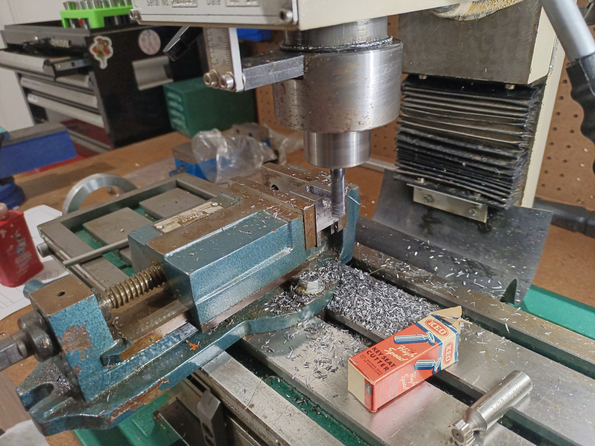
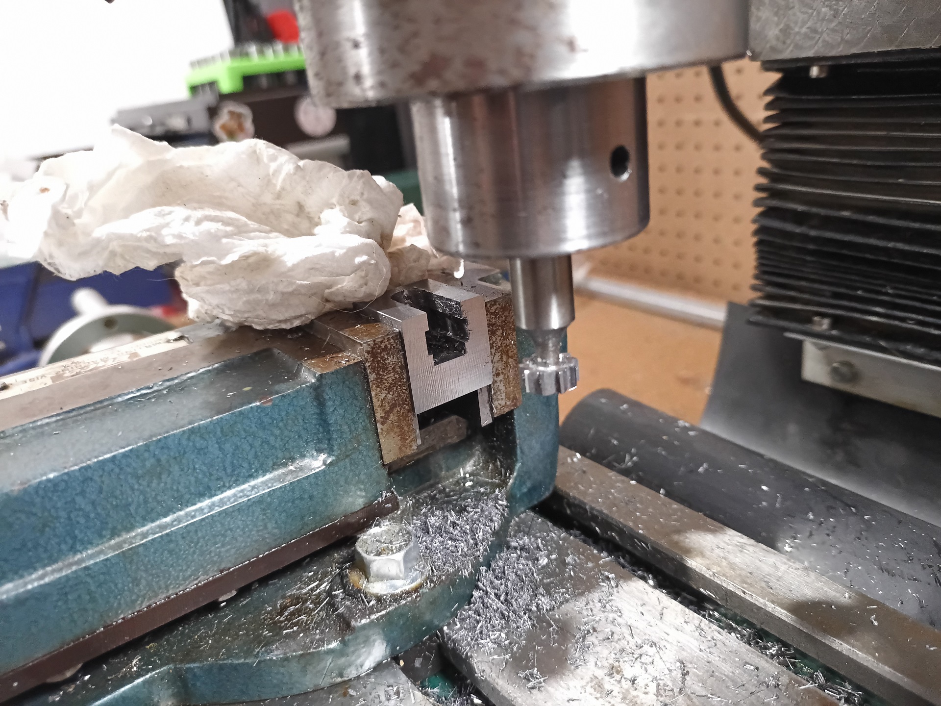
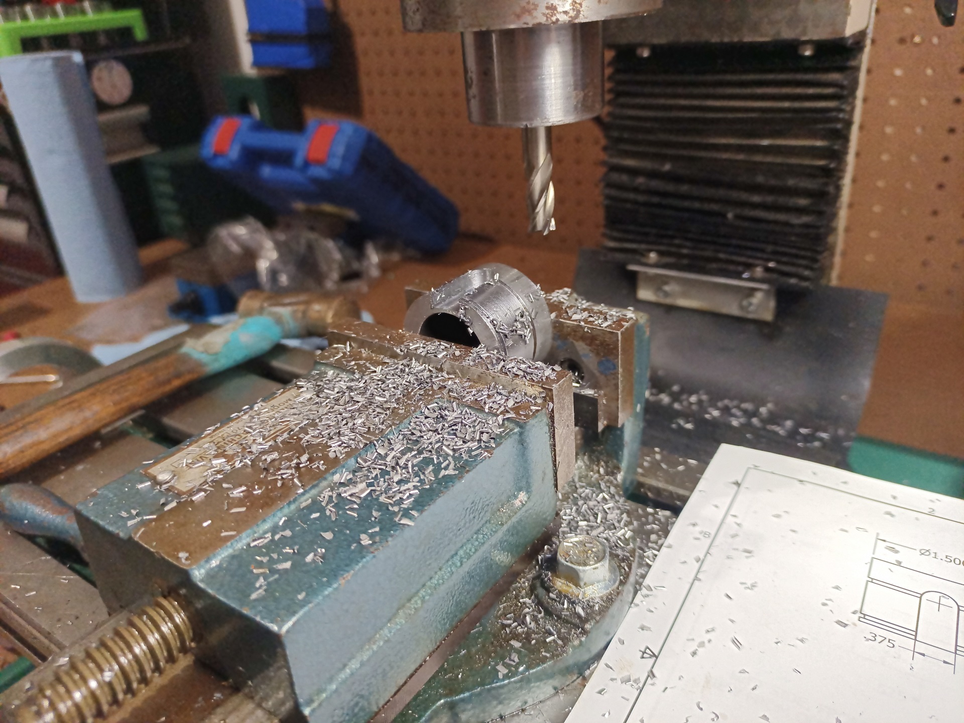
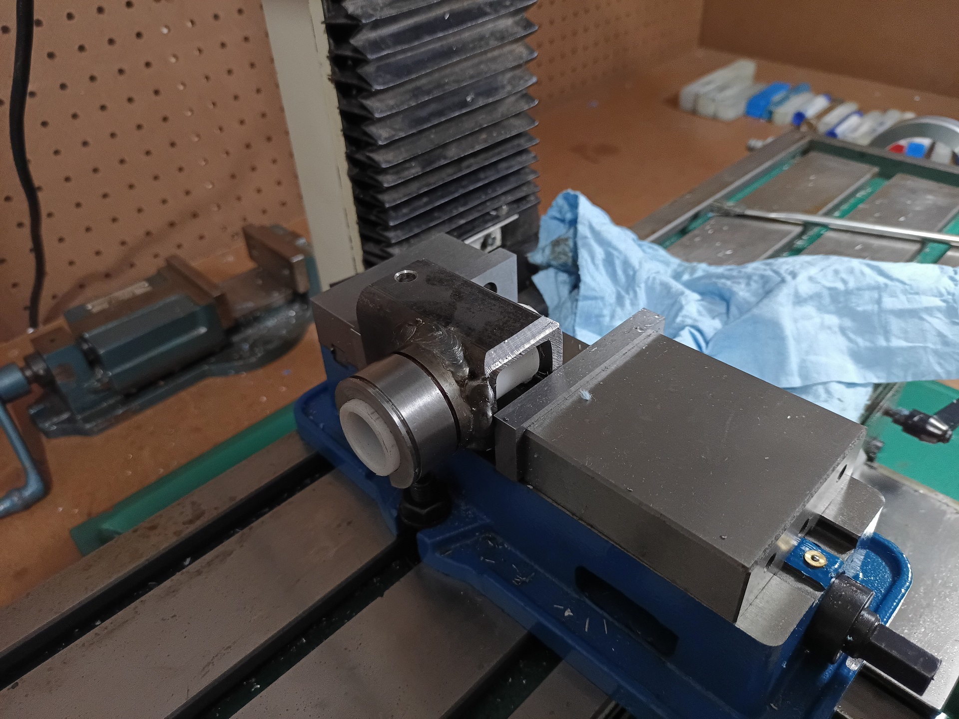
To couple the gears to the, uhh.. end effector of choice, I’ll be making another welded hub. This time, it’s a 1.5″ diameter thick-walled steel tube welded to the socket. The outer diameter of the tube will have a keyway machined, basically turning it into a big keyed shaft. The gear segments slide on and are retained by a snap ring, my former worst enemy but now favorite nation. I’ve also backed down to three gear slices for now since I was very much running out of horizontal space.

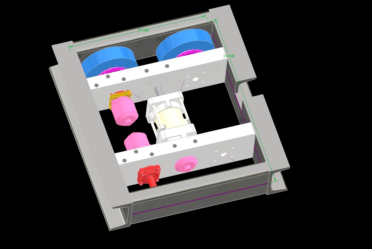
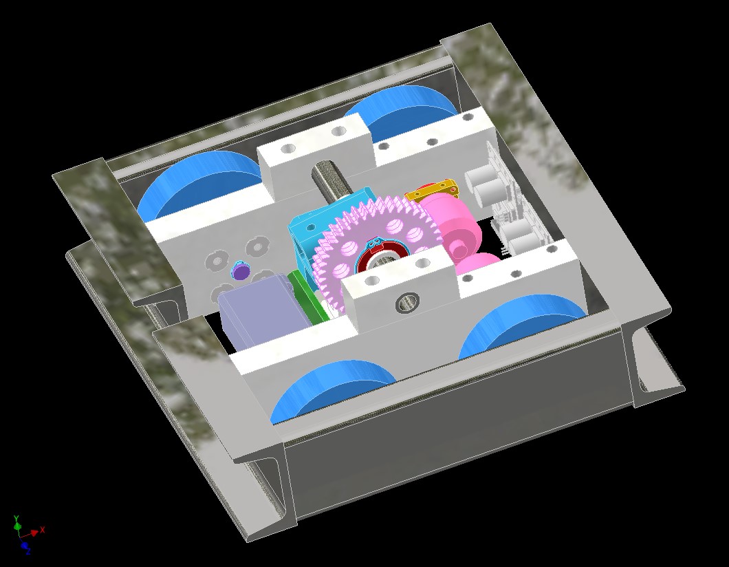
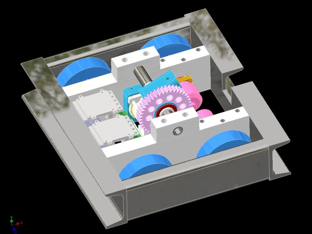
In another episode of “Move onto something else while I haven’t finished the first thing yet”, I began thinking ahead to where to put the internal parts. With the two larger motors now occupying space on one side, an even bigger motor now occupying the central section, and the need for clearance to swing the Eggplanter, I faced a challenge of where to put things like motor controllers and batteries.

Also it didn’t help that the Brushless Rage is the size of a bus compared to modern BLHeli and AM32 enabled ESCs, but… already have several.

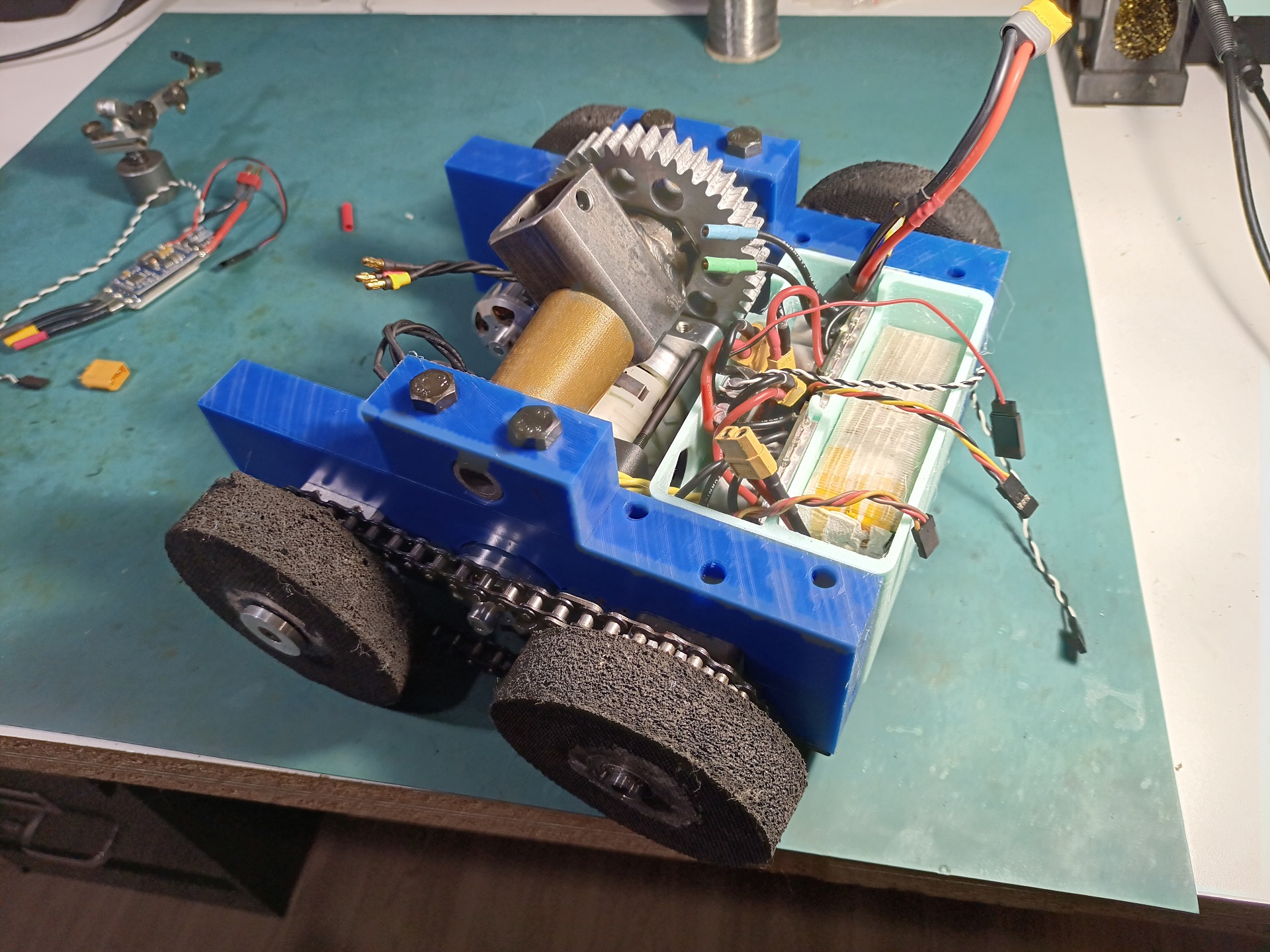
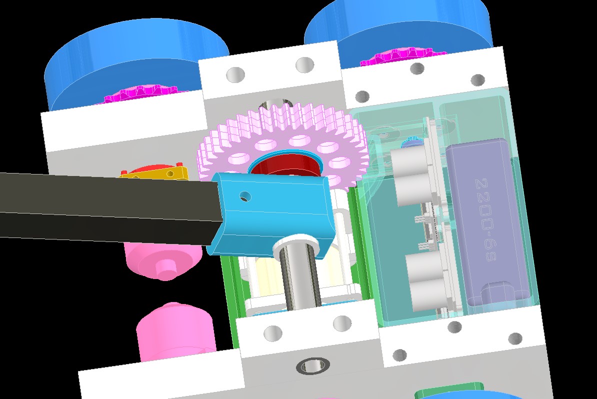
The solution? Turn the damn assembly around! There was now no longer a reason to try to keep everything next to the drive motors. The motors create a convenient gap in the middle for something stick shaped, so let’s make them the “front”. I’ll just make a bottom armor plate and probably a 3D printed dust cover for them. This freed up a contiguous volume to arrange my bus parking lot!

I began “flowing the bracket” around all the parts. This configuration of Brushless Rage and battery offered the most remaining volume to pack wiring as well as a 3rd ESC for the weapon motor. For that one, I was going to use one of my surplus SimonK swap ESCs (specifically the old Spider ZTW 80 amp, of which I had a bundle). Is this robot just a means to dispose of dieselpunk-era parts?!

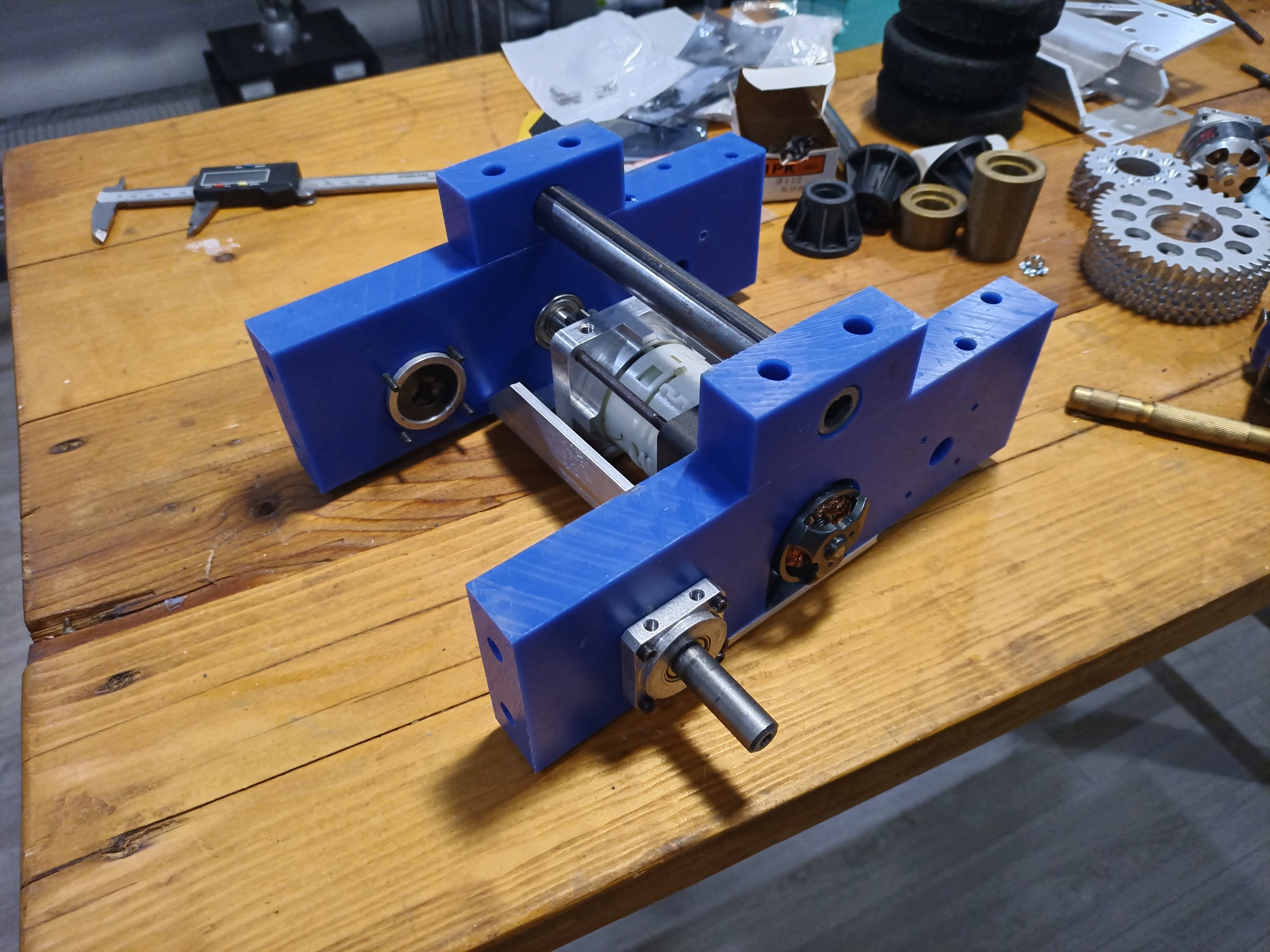
I also dispensed with the separate bearing holder bracket. The DeWut motor shaft will be supported by a bearing in a pocket in the frame rail. This approach has a better load path because of the forces not having to first travel through the weakest part of the aluminum bracket. However, it does turn the “drop out service” into a “slide then drop” because the motor shaft will need to scoot out of the bearing first.

That’s why I said I was running out of horizontal space above – the DeWut had to now be positioned slightly away from the other frame rail so I can slide it back around 1/4″ after removing the screws.

It was time to get building! First off, I started off with testing the fitment of the DeWut conversion. Stay tuned for more Susquehanna Boxcar adventures at Dragon Con and Motorama!

The Belated Motorama 2023 Recap: Return of the Susquehanna Boxcar

Somehow in the midst of the most unscoped, sprawling big-integration project I’ve ever found myself in, I managed to pop out yet another dumb robot! Last² year for Motorama, I spawned the Susquehanna Boxcar, which was a quick-build 30lb Sadbot using pretty much only on-hand components (I mean…. I allowed myself a trip to the hardware store and some random bolts from McMaster). So, for 2023, as I was seeking to distract myself from constantly wrenching on the ven, I decided to bring the bot back. In terms of actual timeline, this build occurred some time between The Stuffening’s conclusion and The Driveshaftening.

While the original build was conceptually sound and drove alright, the mild-wound brushed 550 motors with the spur gearing ended up being prone to burning out. Even with the RageBridge current limiting set rather low, the windings were fine enough that prolonged pushing (or binding in the drive side) would begin cooking them. By the end of the event and in the rumbles, it could barely move.

The easier way out was to just go brushless. This is a statement that, about 10-something years ago on this very website, was almost an absurdity to hear… but that’s the march of technological progress and Chinese meme manufacturing! I had a large stash of SimonK-flashed AfroESCs left over from those days, as well as a few other random SimonK/BLHeli enabled controllers. Nowadays, the new hotness is AM32 which is very promising so far for a couple of builders, but I don’t own any of that hardware yet. This build of Susquehanna Boxcar will help me draw down my existing stash of parts and equipment even further, so it’ll make sense to take the jump to something more modern later on.

The plan was pretty much the same as the first build. Just four motors with a single open spur gear stage to the wheel. The motors I picked were some NTM Propdrive 2836s from HobbyKing, probably destined originally for some kind of Roll Cake or Colsonbot. I had three of the same motors, so I decided to get an extra few from another builder. Next, to give these motors even more of a leg up on the world, I specified 6 tooth pinions, to be custom-made from cold-drawn “pinion wire” (gear on a stick) to be purchased from SDP-SI.

Yes, within the first half hour, I’d already broken my “No spending money” rule. It’s now… No Spending Money™

The smaller pinions allowed a total reduction of 10:1 to the 60 tooth drive gears. This thing will be quick, but I had no doubt it would drive well.

One of the issues (of many) that plagued Susquehanna Boxcar last time was that the four motors were independent from each other. To do this effectively in a 4WD chassis, each motor really needs a lot of torque and power overhead in case you get tilted up (which WILL happen) by an opponent or engage in a pushing match which tends to load the back set of wheels. The little mild-wound 550s….. did not have this.

In lieu of figuring out how to re-engineer a chain or belt drive onto the thing, I decided to just plop a giant bull gear in the middle. With some geometric massaging, I found that I could fit a 73 tooth gear in between the two wheel gears, offset slightly, while keeping the motor pinions from barely touching it.

Oh, yeah, the other constraint was that I wanted the motors as far inboard, towards the center of the bot, as possible. This was to make them less obvious targets as well as to let me have more volume for electronics and batteries. So, all together, this design path ended up working out quite well.

The construction method will be the exact same as version 1, using literally the same bars of UHMW. This is the generated left frame rail. Like before, I’ll be using a 3D printed template/pattern to spot the holes before drilling them, in lieu of having a milling machine with a readout or doing it High School Charles style with all-manual layout.

The drill gearbox for the Multifunction Poking Implement is mounted identically, but pushed forward a little more. There were two reasons here. One, to give me more space for electronics, as the motors are spread farther apart than before and so the contiguous space at the very back has changed in shape. And two, because I wanted to be able to run a larger sprocket on the poker hub. Having the motor directly underneath limited the sprocket selection significantly.

The poker hub this time uses a #35 sprocket instead of a #25 for greater durability. I wrote off using this #35 sprocket (from my big basket of random sprockets) last year because it was larger than the #25 I ended up going with. But now, with the motor moved, it can fit.

I went ahead and modeled the bull gear that bridges the front and rear drive wheels. It’ll spin on two FR6 type ball bearings and be unceremoniously suspected on a single shoulder bolt with a locknut. I’ll have to see if I can even make the tolerance stackup of manually drilling these holes work with it!

I generated the template that is to be used for the frame rails, and made sure to design it so it’s as hard to look at as possible. There’s no real reason for the many unrelated holes, just an aesthetic choice. If anything, it made the print process longer and made it less rigid.

The template aligns with the UHMW stock using three dowel pins. Two on the bottom side for the parallelism, and one touching the upper corner.

The Makening

The first step is to take apart the old and salvage what I can for the new! It wasn’t that much, sadly. The only things I could really reuse from this chassis is the outer steel frame itself which left the event mostly intact, and the four axle bolts.

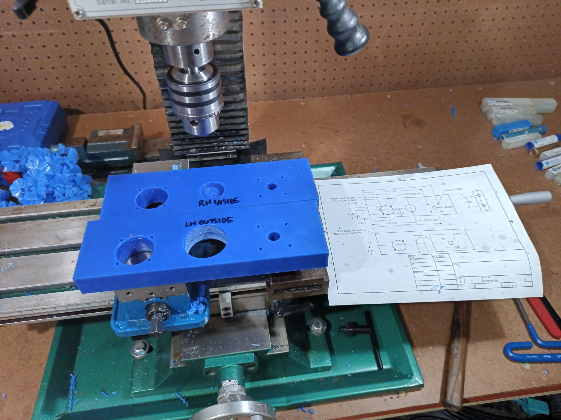
Using the template to pilot drill the holes did work well enough, but I still needed to use the Benchmaster, Master of Benches for a counterboring operation to make pockets for the drive motors. I didn’t have a good means of ensuring that a Forstner bit (to make the flat-bottomed hole) started aligned with the pilot hole if I did this on a drill press, so I just sucked it up and spent a few hours counting dial revolutions. Still, this was more of a “close enough” operation, as the motor’s mounting axis is determined more by their countersunk mounting screws. As long as they didn’t touch the side of the pockets…

All the parts are labeled with their orientations because I will definitely mess up making the correct side otherwise!

Going back to construction methods I haven’t really utilized in a bunch of years, really dating back to my pre-machining era. These frame rails were just squared up and clamped together, with the holes laid out by hand.

In a day and age where most people default to 3D printing frames, and it’s common for newbies to think you have to have a 3D printer to get started building, I still think there is value to a frame banged together from UHMW blocks. It’s workable with almost all tools, and is a solid contiguous mass for you to zip things together wherever you want (versus 3D printed hollow infills… reminds me of drilling into drywall trying to mount something at the house)

I expect this mod to go very poorly.

That’s a 35mm class outrunner motor which shares a bolt pattern with the RS-550 sized drill motor. I was going to cram this into the drill gearbox after boring the pinion out to 5mm. Putting something like 3-4x the power of the drill motor through that gearbox is most likely going to make it very angry. My guess is the output stage pins will shear or I’ll start blowing gear teeth.

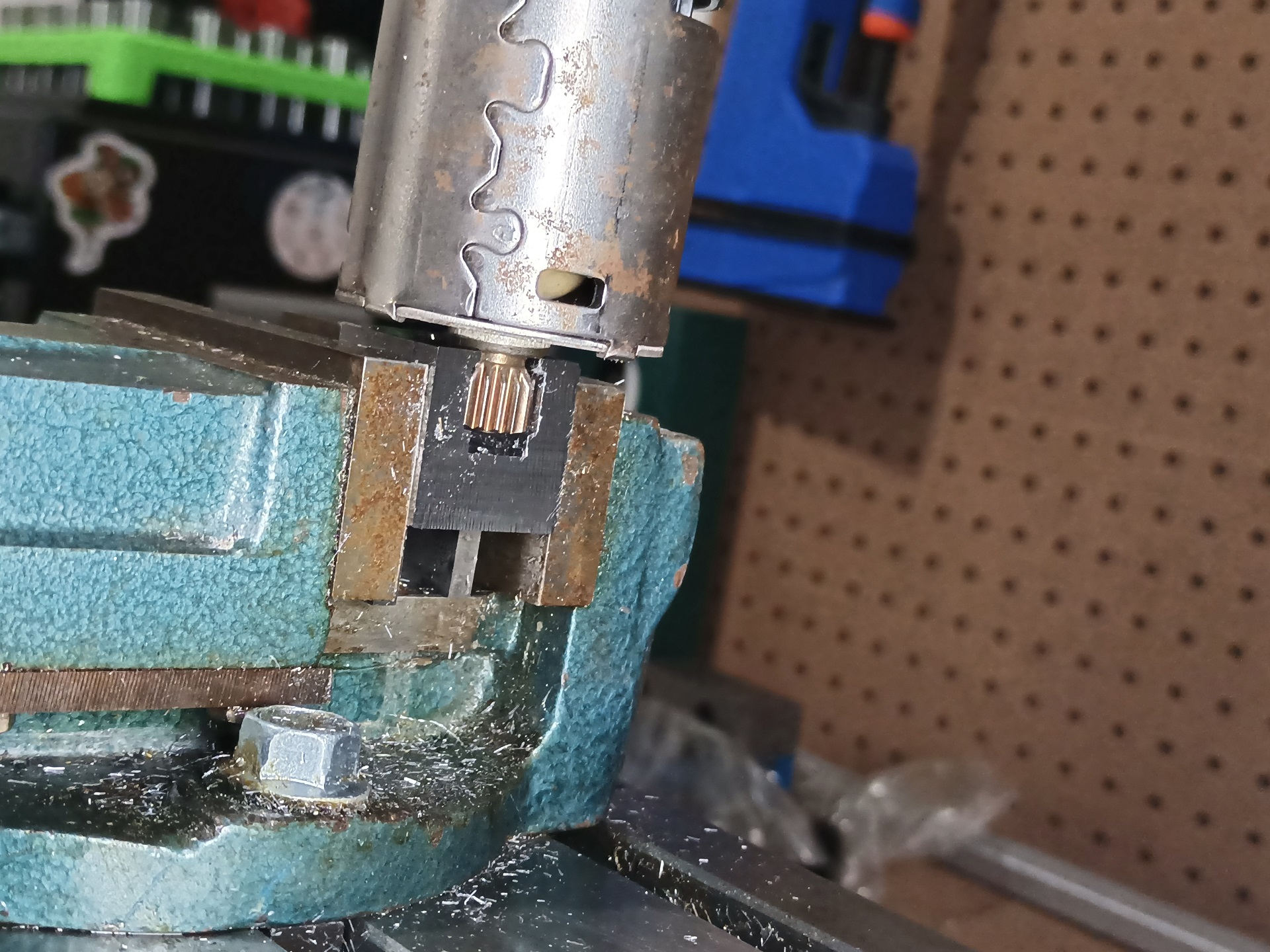
I went ahead and prepared both of the 3536 motors I had for drill gearboxes. It’s easy to keep making parts in the same sitting once you get rolling and all the tools are already out and set up.

Test fitting the bull gear here. “Shoulder bolt” decayed very quickly into “well, i’m too lazy to remove this cap screw and nut”. I found that I had the tiniest amount of axis position adjustment because the threads on the screw are a very slightly smaller diameter than the hole.

To my utter surprise, the gear mates all worked! Only a small amount of backlash was present and the bull gear didn’t really need any special treatment, like forcing off to one side of the tolerance/slop distance. Now, I used to do 32-pitch gear mates by hand on the drill press back in high school, so if I can’t even manage 24-pitch nowadays that would be quite the blunder.

Moving onto the Multifunction Poking Implement, it’s put together the same as last time: Just a square tube, appropriately drilled through, welded to the sprocket

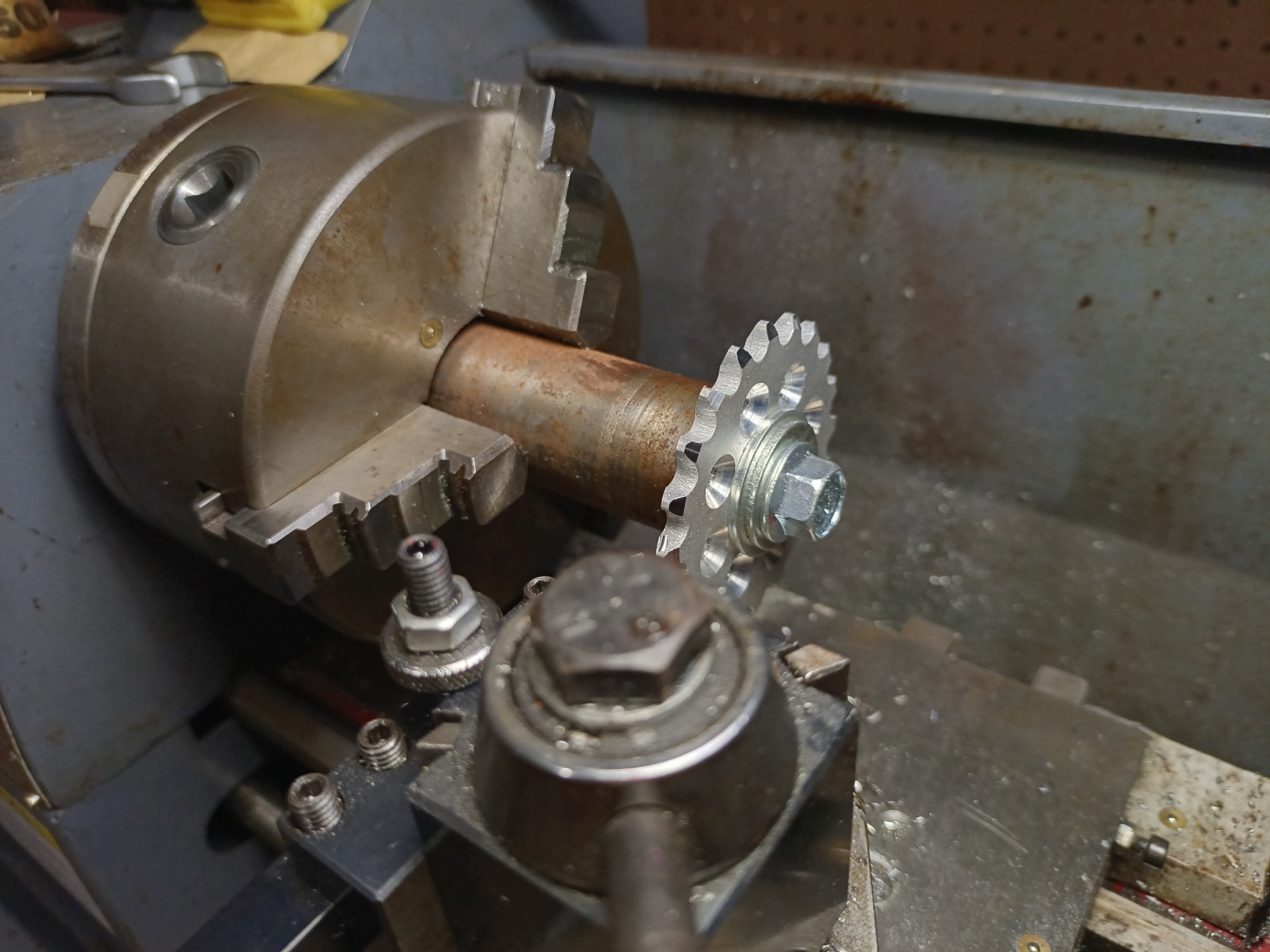
As I touched upon before, I started with a #35 sprocket this time and turned it down (very painfully – this was a lot of sitting there cranking Tinylathe 0.5mm of feed at a time) to the thickness I needed. Then I just apply some quick blasts with Limewelder using a steel tube as a locating dowel in the center.

Now, for the drill gearbox sprockets, I had to get a bit creative. The smallest #35 sprockets I owned were these 8-toothers… but they already had a bore of 3/8″. The drill gearboxes have a 3/8″-24 threaded output shaft. There’s too little meat on the hubs to bore it out and sleeve it (I’d basically cut the sprocket bit off the hub if I tried boring it out).

The solution: Well, the welder is already out and warmed up. I just filled the hole up with Weld™. It’s like a Direct Edit button, but for real life.

Next, I chucked the sprocket up and treated it like I would any other! Drilling a center hole, then successively larger holes (the weld alloy is harder than whatever this is made of), then finally running the 3/8″-24 tap through it.

That worked amazingly. So that’s pretty much all the mechanical work going into this bot. Conceptually very simple, using techniques I’ve second-natured for years now, and not much to go wrong. Perfect zero-brain-cells-left build for a time I was mostly preoccupied with planning the L.E.W.D.

I even went and purchased a new Harbor Freight Multishovel to complement the slightly beat up (but serviceable) one from last year. All I do to these is remove the handle and stuff the stump into the adapter sleeve that sits in the hub tube. The folding telescoping sleeve thing still works. Unless destroyed, I can transform it back into a Multishovel.

Top and bottom lids for the rear section are once again made from 1/8″ G-10 grade Garolite laminate, a pleasant and multipurpose material. Pleasant, except the part where it slowly consumes your HSS/carbon steel tools from abrasiveness and also leaves little fiberglass splinters everywhere. The top and bottom screws got an upgrade to 3/8″ lag bolts. No particular reason here besides unifying the tools needed to fix this thing.

Between then and now, I grew a reel of TPU filament that was only used a little. I decided to expend more of it making the electronics cave for this thing. It’s just sandwiched in place between the top and bottom plates, then retained on one side by the steel box frame and on the other by the protruding axle bolt heads.

It’s designed to fit a 4S 1.8Ah battery, compared with the 7S flat battery last time. Nothing wrong with that battery per se, but I was using the smaller AfroESCs which weren’t rated for that voltage input. Keeping the voltage lower also kept the bot’s calculated top speed from being comically high (like 30+mph, unrealistic to achieve in the box) and makes blowing everything up much less likely.

The power “switch” and power distribution was kept simple with a single gigantic squid assembly. The big solder joint in the middle brings together four 18 gauge drive motor controller wires, a single XT-60 on 14 gauge for the poker, and an auxiliary JST-RCY (literally “a JST Connector” when left unspecified, by the way… not many people know the actual product line name) for whatever else I want, like gaudy LEDs.

This was not fun to solder together, but I was in no mood to design some kind of bus bar or power distribution terminal block system.

After some more massaging and fineries, here is the Susquehanna Boxcar for 2023! I was highly pleased with how this bot drove, actually. The four SimonK-based drive ESCs were put into reversible mode with non-synchronous PWM (they can both add power, but not regenerate from each other – no fighting through the gears) but idle-throttle braking enabled. That way the bot still stopped quickly when I centered the transmitter stick and didn’t keep coasting.

The Motoramming of 2023

For the Motorama, I was in charge of making the trophies once again using asslaser69. I got creative this time and changed the design to use a lighted base, which we liked and so the organizers commissioned a boatload of them from Amazon. This was an cute little change from the rushed-together laser cut trophies of 2022 which were made because AAAAAAAAAHHHHHHH WE DIDN’T DO IT

And so, once again, we deal with the consequences of having me be in charge of something. IYKYK, IYDK,DGI.

I elected to do a “clean trip” this time. Vantruck was obviously not available for the job like it was in 2022. Plus, at this point, I was beginning to cull my random van buying and breakdown related expenses, appraising my resources in preparation for the New Robot Trap House. So, the soulless-but-least-likely-to-explode van it is.

My first (and only) real tournament match was against EVA (stream archive link), which used a pushy configuration for the match. Right around halfway through, I lost a motor on the left side, and later on the mutual pounding also (like I suspected) sheared off the planet gears inside the ol’ crusty drill gearbox that had been brushless-swapped. It was trapped upside-down :(

I was slated for two fights that day, and taking the thing apart to get at the motor and the drill gearbox took longer than I counted on. It turns out the extension cable I made to get to the ESC had pulled out of a connector joint I thought was well-taped, but I had to take the bot apart enough to get to that point to find out. The drill gearbox and motor just needed outright replacement.

You’re only guaranteed 20 minutes turnaround at most of these events, Motorama included, and that can come to haunt you really quickly if the matches ahead of you move fast due to knockouts, or if people forfeit fights. The usual 2-ish hours I was hoping to have turned into only 45 minutes or so. So with my time having come and gone, I decided to just prepare Boxcar for a series of really funny rumbles.

And no Susquehanna Boxcar moment would be complete without a comically sized vegetable hanging off the end of it. Behold, the Papaya of Redemption. As I promised, I headed out to the only Asian grocery within like 50 miles or something and picked up a couple of dumb… uhh, end effectors.

Here’s the stream link for that rumble! It didn’t do that much during the rumble because the Papaya of Redemption almost immediately broke the spare drill gearbox, and then became stuck against the frame.

Once that was very rudely and inconsiderately removed by Phenomenon, I guess it ripped something completely apart inside with the toss from its weapon (maybe turning a stripped gear or two into powder), and I had some vestigial function left on the Multifunctional Poking Implement. Upon which I got promptly stuck sideways on the wall.

I also agreed to a grudge fight afterwards against Big Cookie, which is a bristlebot using the purposefully unbalanced shell to wiggle around on a series of tilted wire brushes. It demonstrates translational movement like behavior under some circumstances, but hits crazy hard because it’s basically entirely weapon.

For this fight, the Danger Potato made a return, because… why not.

I assembled a composite drill motor out of the wreckage of the two I brought, so I can swing the Danger Potato. This was 100 percent not a good idea, just as I suspected. And I think I understand why I usually spend money on robot parts.

By the end, both of the robots were thoroughly painted in taro starch. Here’s the stream archive time link so the erotic taro-grinding action can be witnessed!

I said Cookie hits hard. Look at the frame on this thing. It’s turned completely into a parallelogram!

Well then… that basically retires this Susquehanna Boxcar because I’ll need to remake the frame entirely to get it back in working order. So, if I bring it back again, I might be forced to… you know, spend money on it or something. Maybe I can use one of the leftover P61 gearboxes I have from 30Haul. Sadly, the days of competitive bots being made from power tool particles is mostly done for except the local back yard stuff, like my very own near-and-dear Robot Battles at Dragon Con. There’s just better gearboxes to handle the power of brushless and lithium.

Boxcar basically lives in a pile of its own wreckage in a tote to this day, because immediately after returning from Motorama, I went into Operation IDIocracy rescue mode. I scrapped the parallelogram along with about 700 pounds of other random metal detritus before the big move. Now that the New Robot Trap House is functional, I am certainly considering bringing it back for said Dragon Con this year!