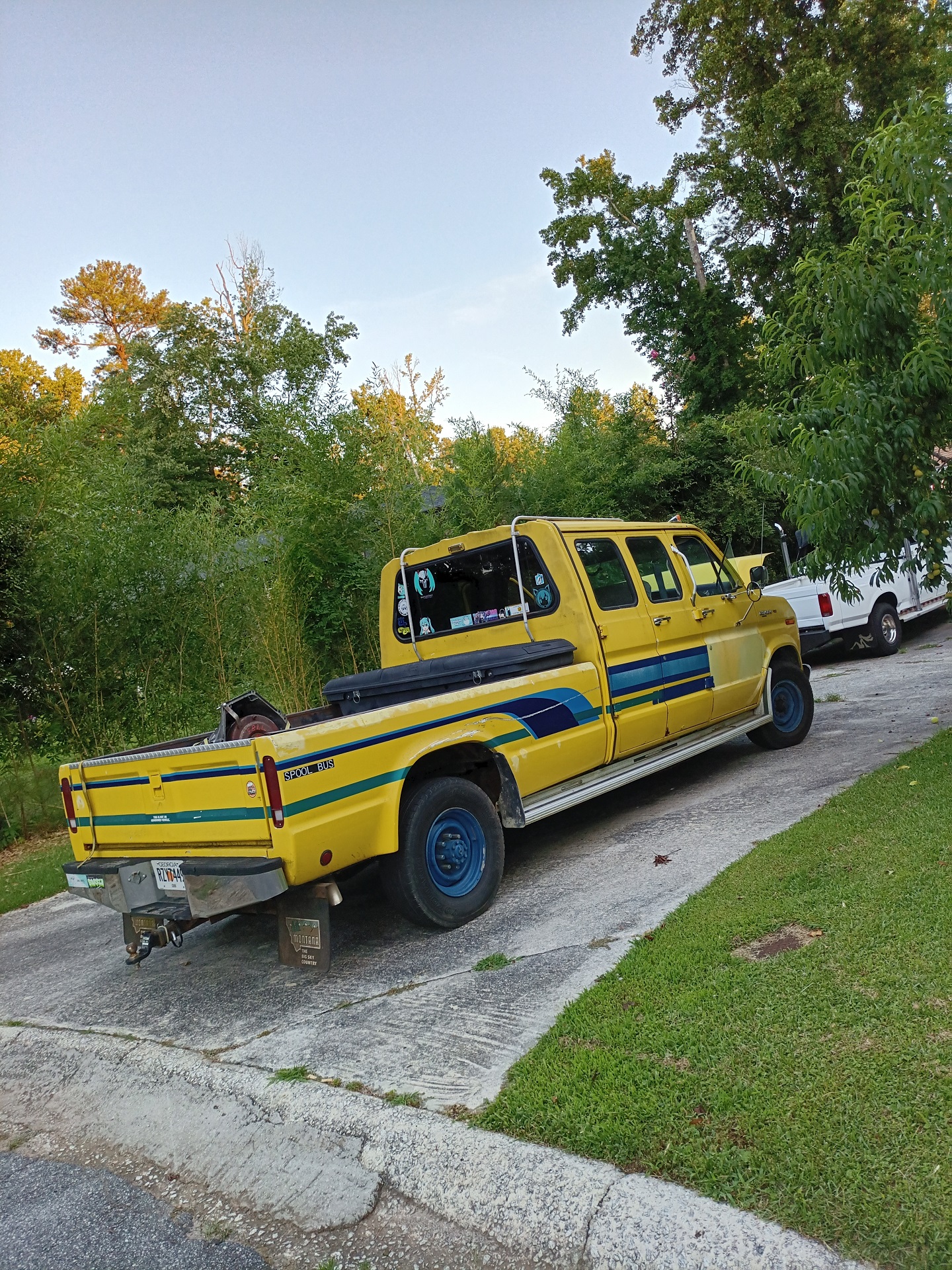
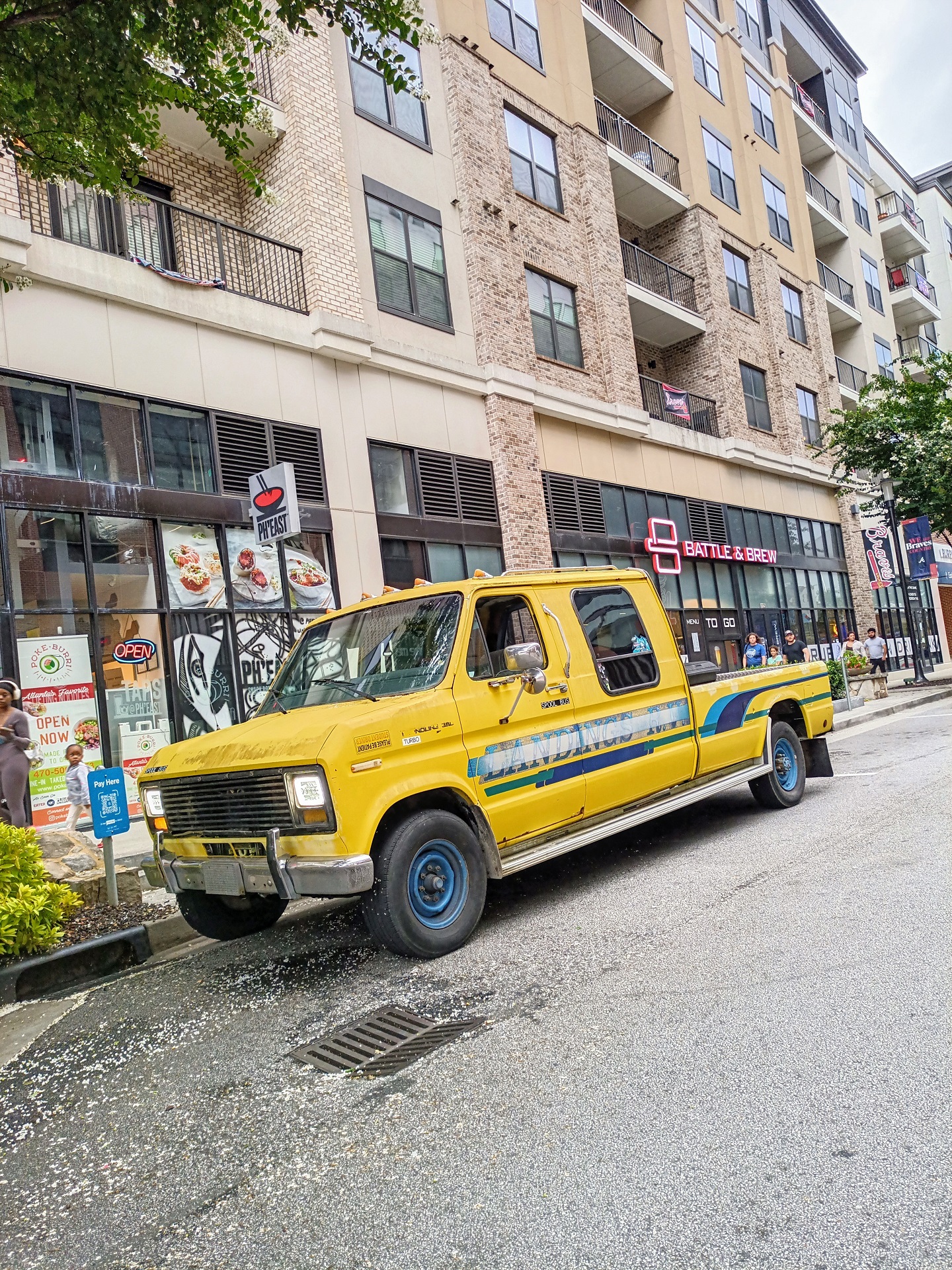
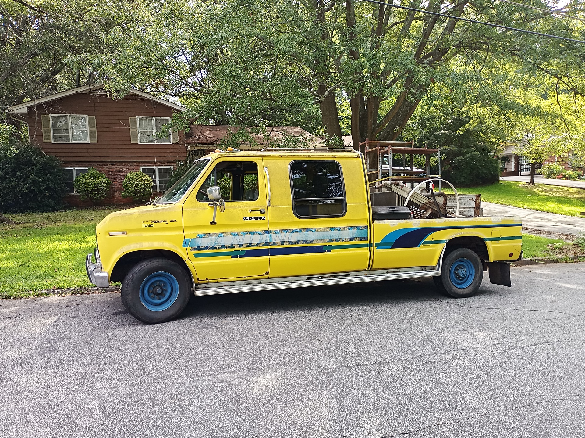
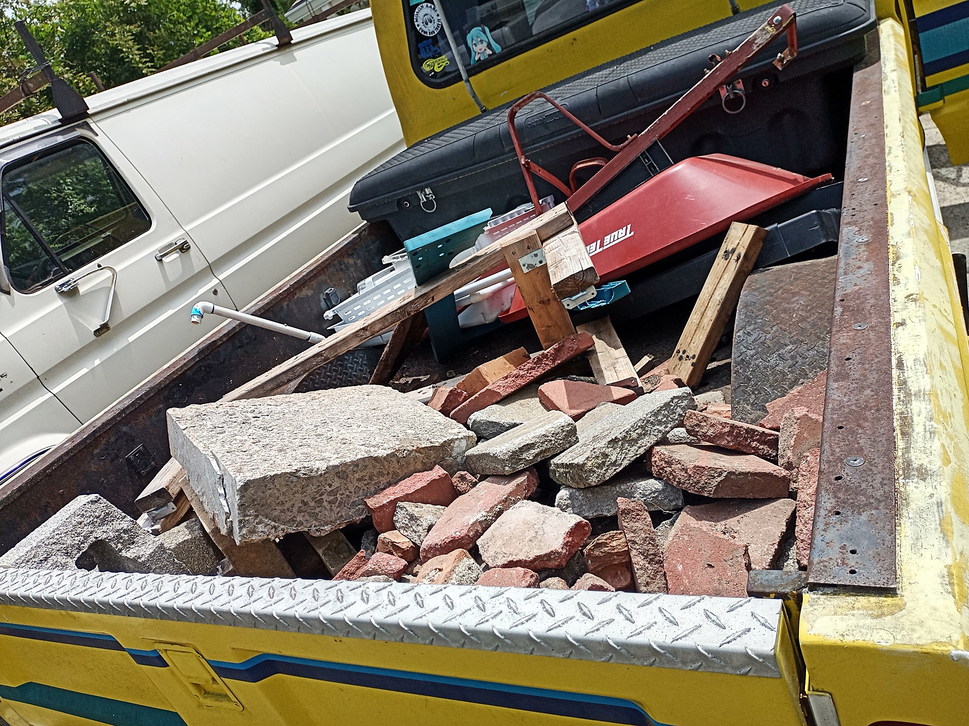
So there I was one fine (a.k.a last) summer collecting some parts for the MOST RECENT PROJECT CATCH (never before seen on this site! Yet!) with Spool Bus, having been recently been re-HVAC’d such that I no longer had to risk dehydration simply puttering it over to the shop or a car meet. The application called for the same model E4OD transmission that I retrofitted into Vantruck as part of IDIocracy whereas Spool Bus and pre-op Vantruck used the older C6 3-speeder with overdrive pods.
For the van chassis, the transmission had to be a narrow year range for drop-in compatibility – 1987 to 1991, during which both the F-series and E-series used shifter linkage rods. Transmissions made after 1991 switched to a shifter Bowden cable and began relying on electronic speed sensors instead of the mechanical speedometer gear. On top of that it had to be for the diesel bolt pattern, because Ford handily lost the bellhousing wars to GM. The transmission would need to be dismantled to change that shifter input, so I wasn’t really keen on making an off-year work.
I stalked a whole bunch of regional yards and found a candidate around 60 miles away. After explaining once again, to another junkyard, that no I wasn’t here to sell the vehicle to the yard, I embarked on my merry way with a new-to-me 1991 E4OD transmission from a dismantled diesel box van. (They were so enamored with the project that I also got the shifter links and doodads for free!)

Now, to get home day to day, I usually pass by one or two water treatment facilities located close to the river where the highways cross. For some reason that day, the area smelled extra spicy and chemically as I approached. Fine, I thought. Maybe they’re doing some kind of pool bombing operation or deep cleaning the poop mash tuns.
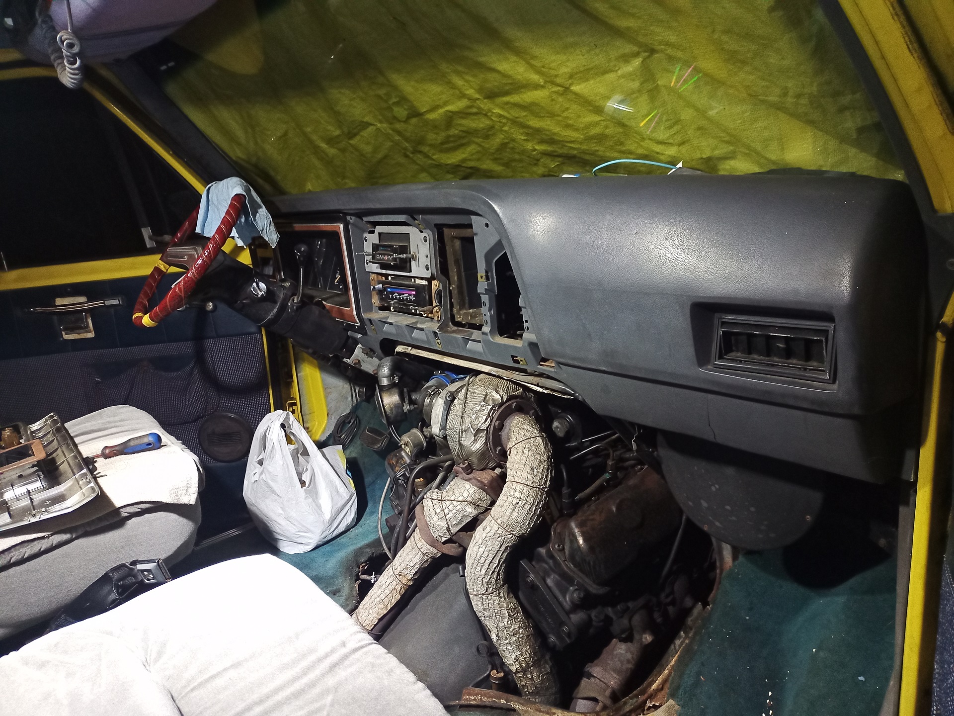
Except then the spicy chemical smell began visibly collecting inside the cabin. Remember, Spool Bus had working HVAC (ok, just H-V and no A/C) again, so it was pulling the stank from somewhere. It was then that I realized the chemical smell was that of burning plastic and PVC wire insulation, not something typically pumped en-masse into the poop fractionation towers. I wonder what’s on fire this time, said I, having become numb to having vans catch on fire for some reason.
My mistake was hitting the brakes to pull over and inspect, which caused a massive smoke cloud to suddenly puff out from the hood vents and into the cabin. This means whatever was on fire was being fed by brake fluid being pumped onto it like a really cursed oil heater burner box.
If we’re keeping score, at this point I’m going 70 mph on an interstate, while potentially on fire, without a way to stop and do something about it.
So what did I do in this absolute situation? Drove the bitch straight home, what else.
I didn’t bother stopping (well, not like I had a substantial choice in the matter) and after being confident that the electrical fire was no longer an issue, manually dropped into 2nd gear and then simply crawled home slowly (Woe is me, for I am old truck, beset by mechanical problems! Hark, my hazard lanterns!) using the parking brake pedal with the unlock handle pulled out to modulate final stops at red lights. I count my blessings that a Ballistic Nissan Altima did not suddenly dot product itself with me.
I am also keenly aware that none of this would have been possible in a new app-car with an electronic parking brake caliper and fully electronic transmission. Honestly, part of my love for old decrepit mechanical things is the ability to force many fallbacks and partial solutions instead of being locked behind software-defined hard fails.
Well, now that I made it home and am clearly not writing an article for The Autopian about how Spool Bus burnt down on the side of the highway, it was time to do some battle damage assessment.
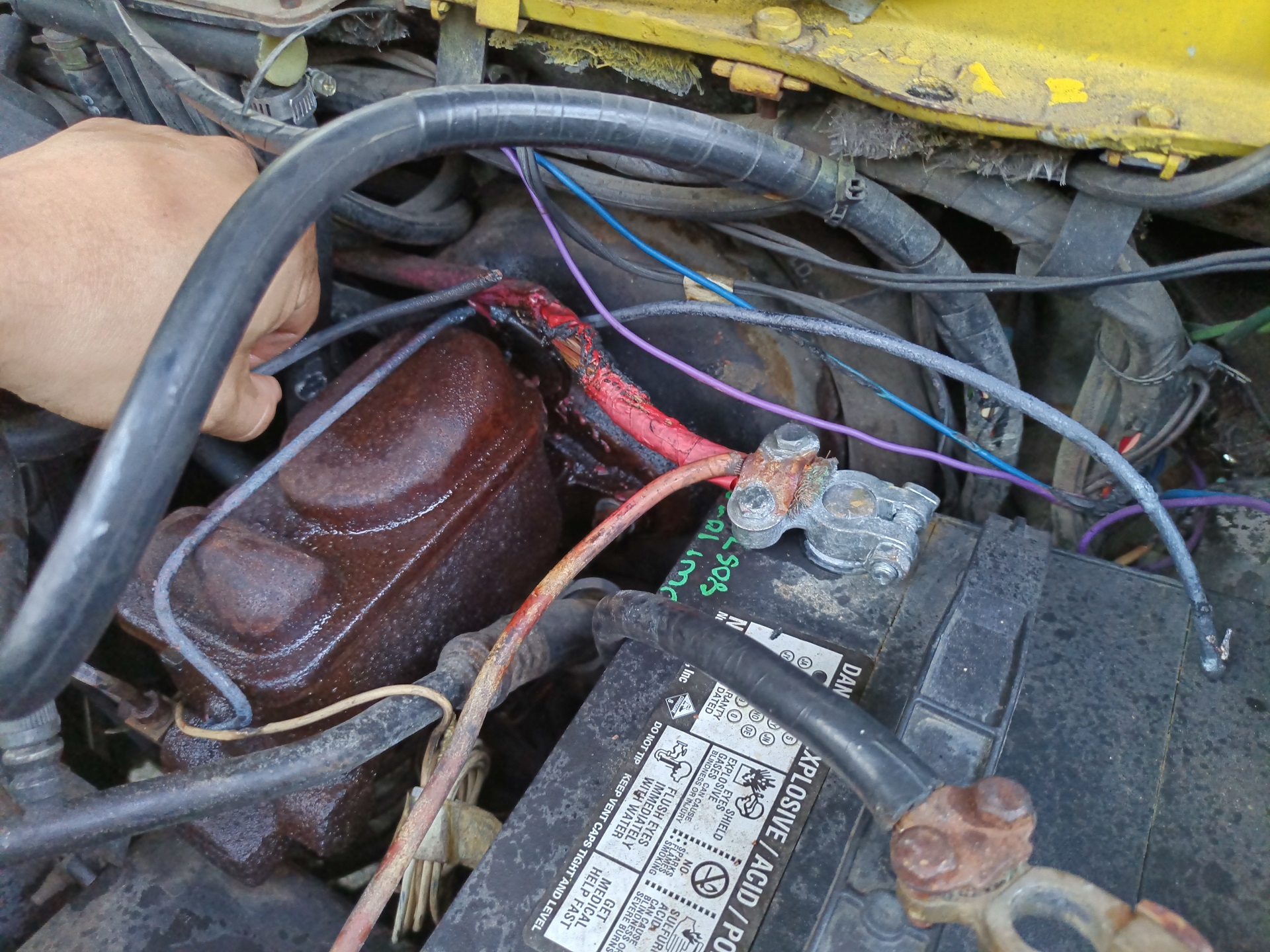
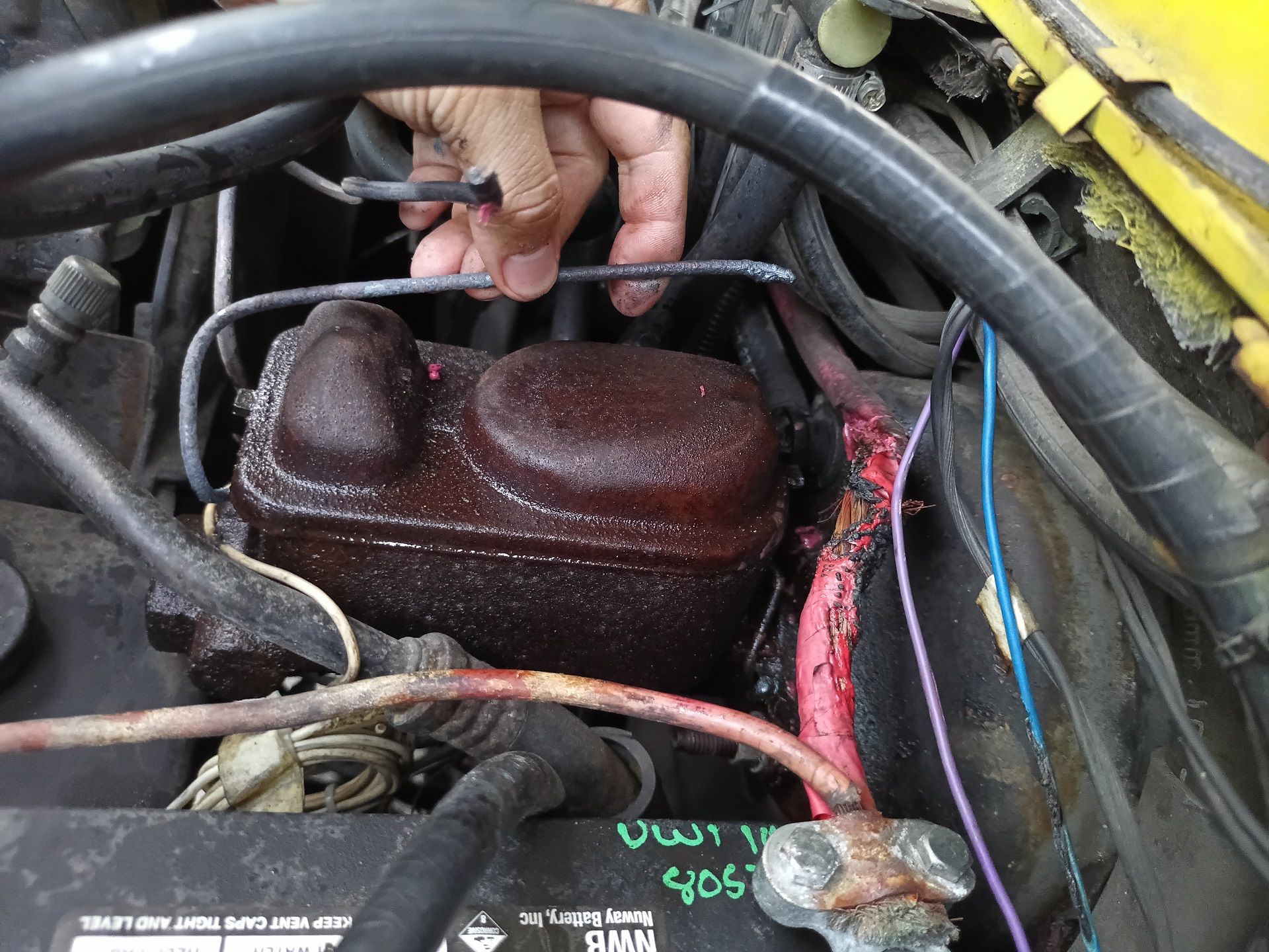
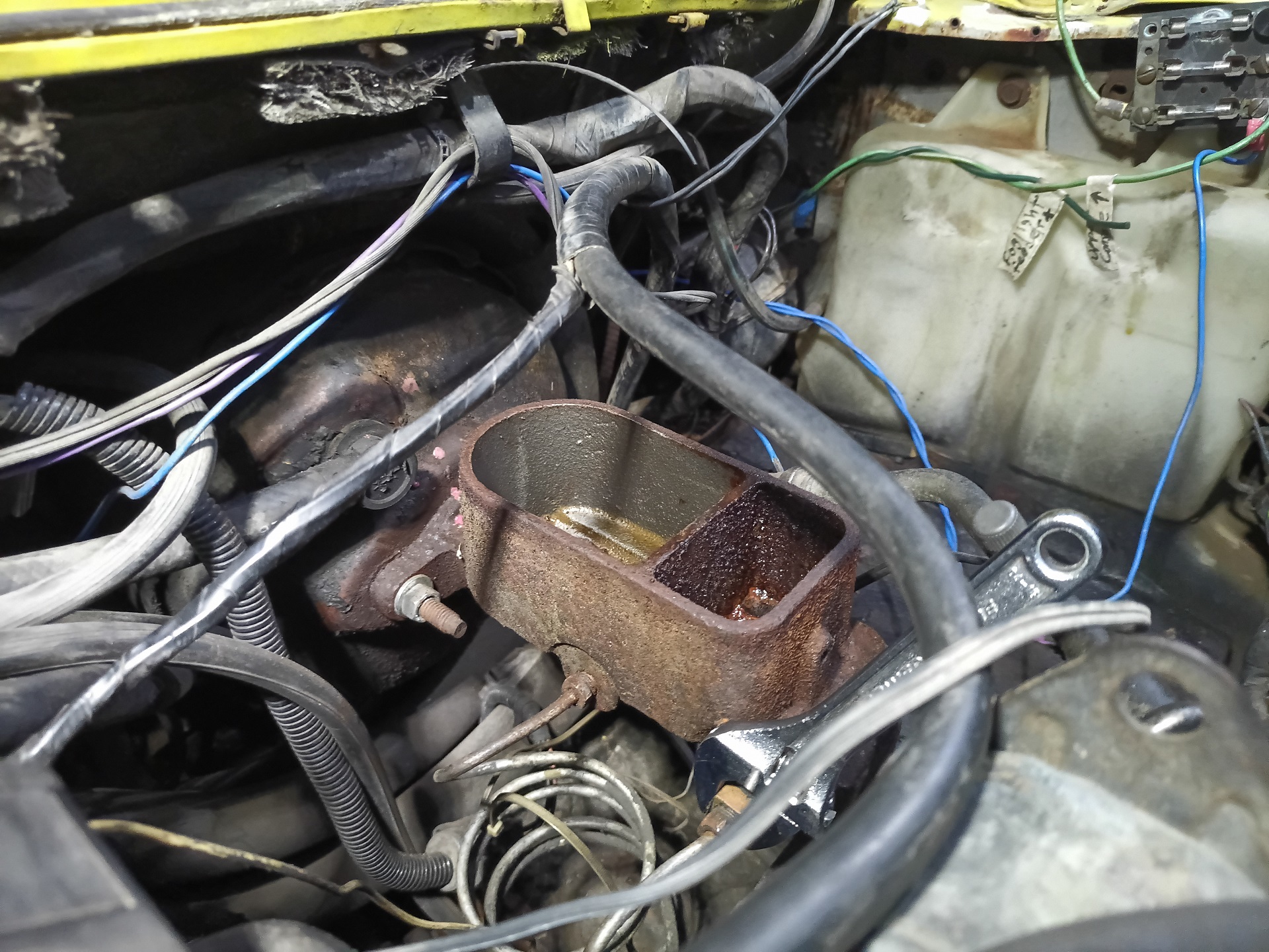
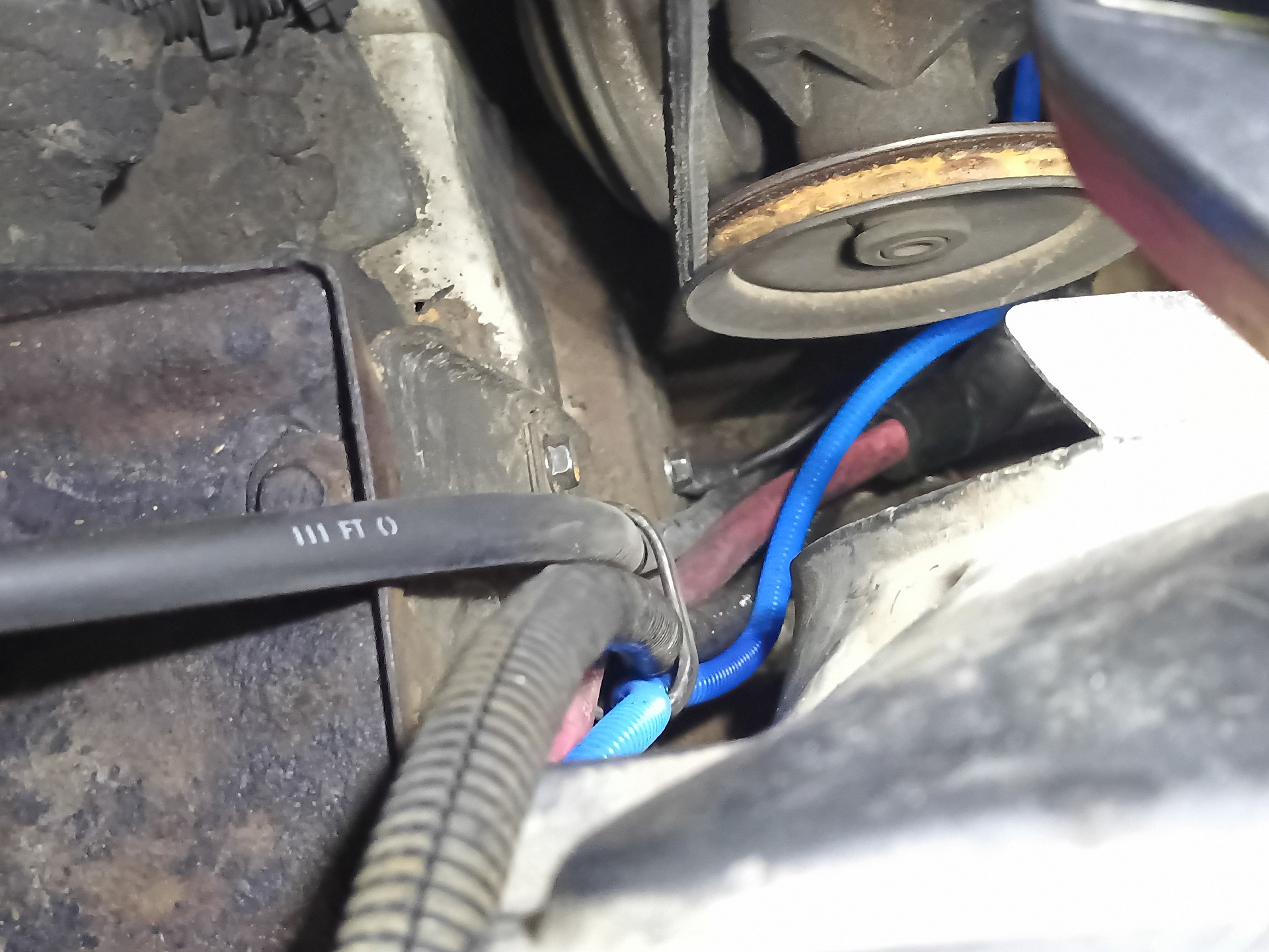
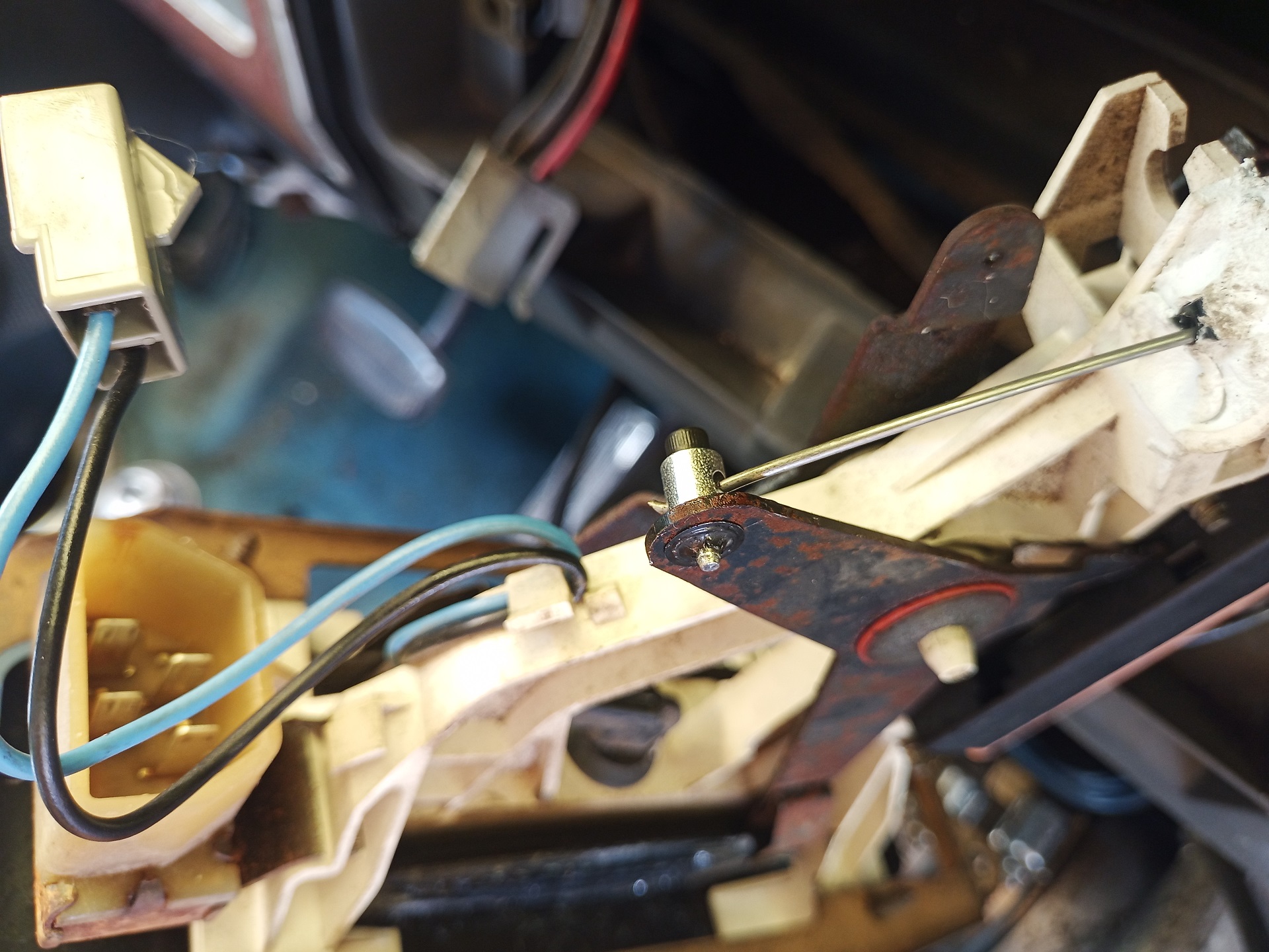
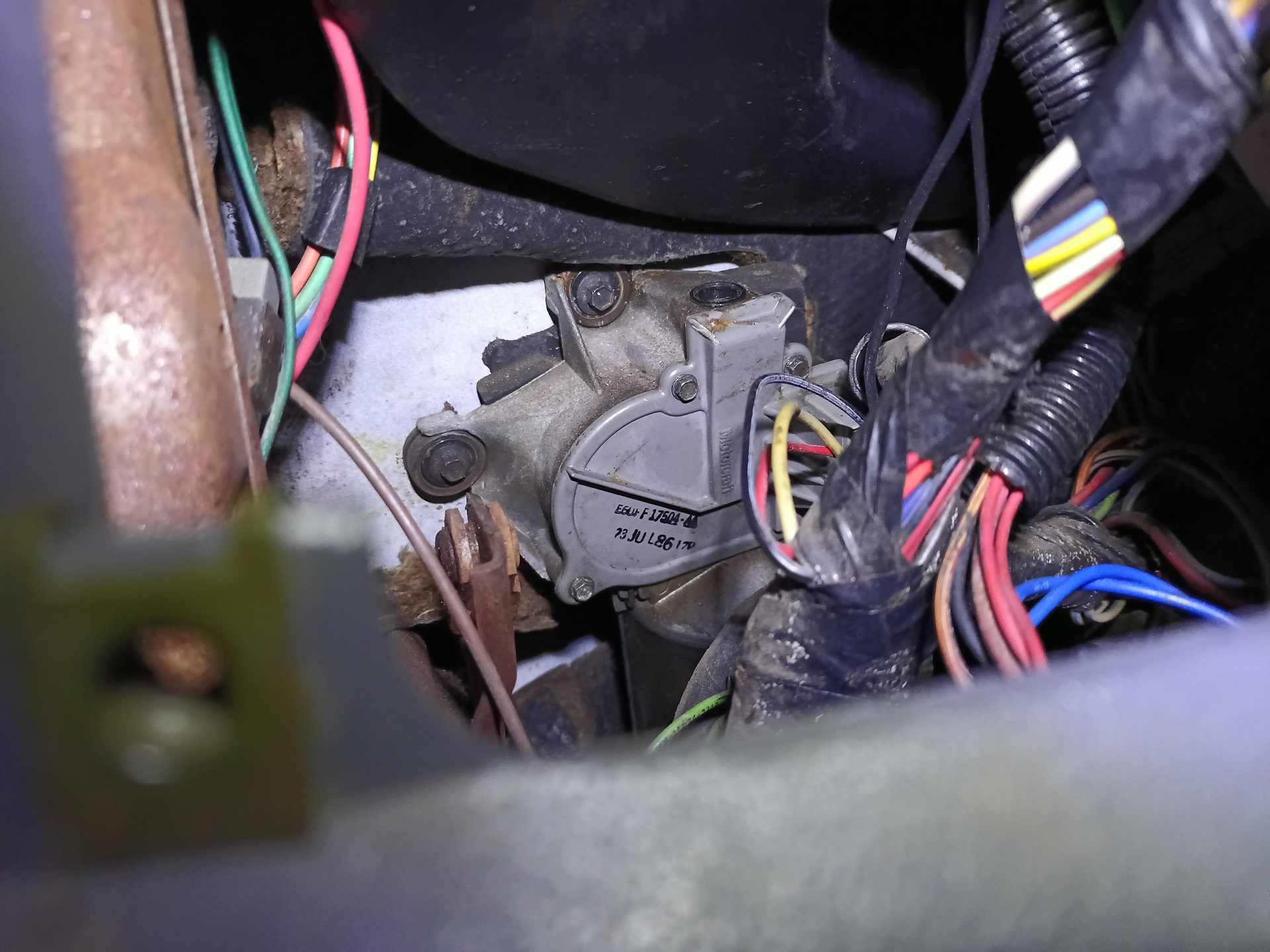
It was immediately apparent once I popped the lid as to what happened. On a lot of older trucks with retrofitted trailer brakes, there is a third brake line that is tapped from one of the master cylinder ports, typically the rear circuit. This extra hydraulic line is routed inside the cabin to a trailer brake rheostat that is actuated by the pedal movement, and that is how power gets passed to the electric trailer brakes.
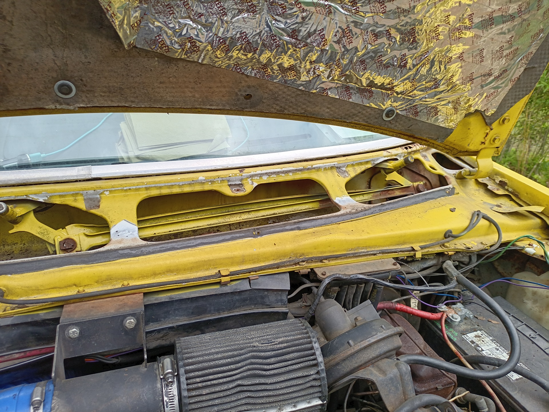
So people just tend to route these lines wherever and Spool Bus came with a particular lazy routing where it just went up and over the master cylinder and punched through the firewall somewhere on the driver’s side corner. What basically happened is at some point, the battery cable that very rudely touched the master cylinder fell out of the old broken plastic cable tray above it, and on my trip home, finally wore through its cracked 40 year old insulation and grounded out through this trailer brake line.
In doing so, it probably heated up and sagged, also cutting through the spring strap holding the master cylinder lid closed.
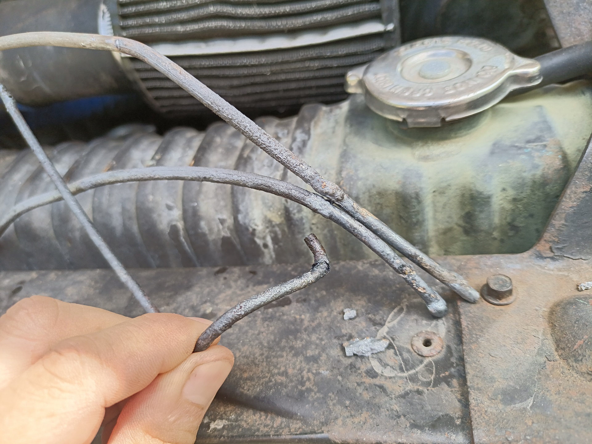
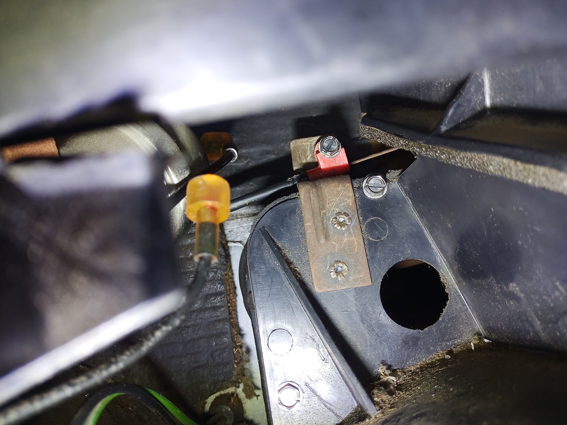
Check out these ends of the trailer brake line and lid strap! They look like they’d been used as stick welding electrodes which….. isn’t far from the truth.
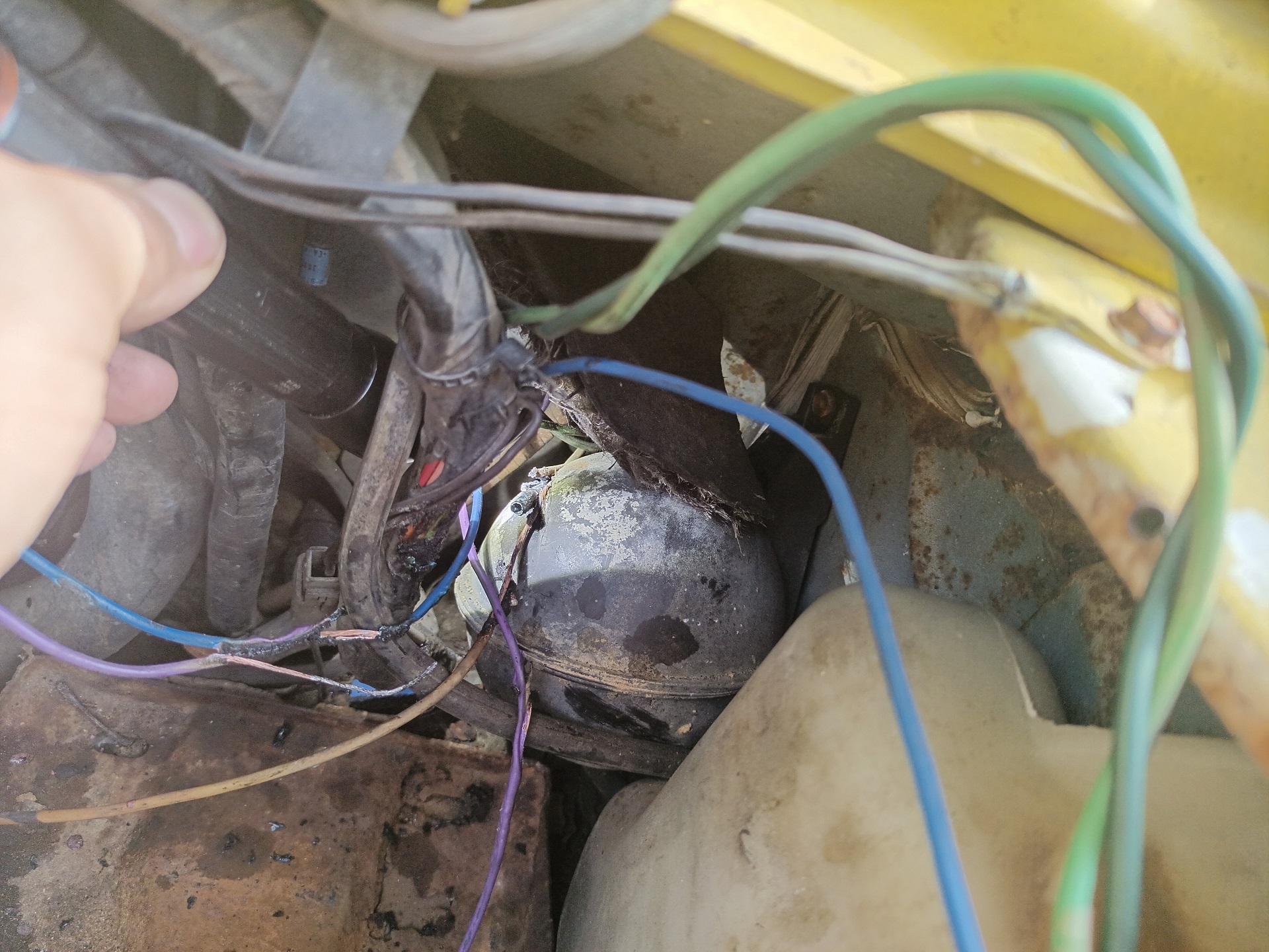
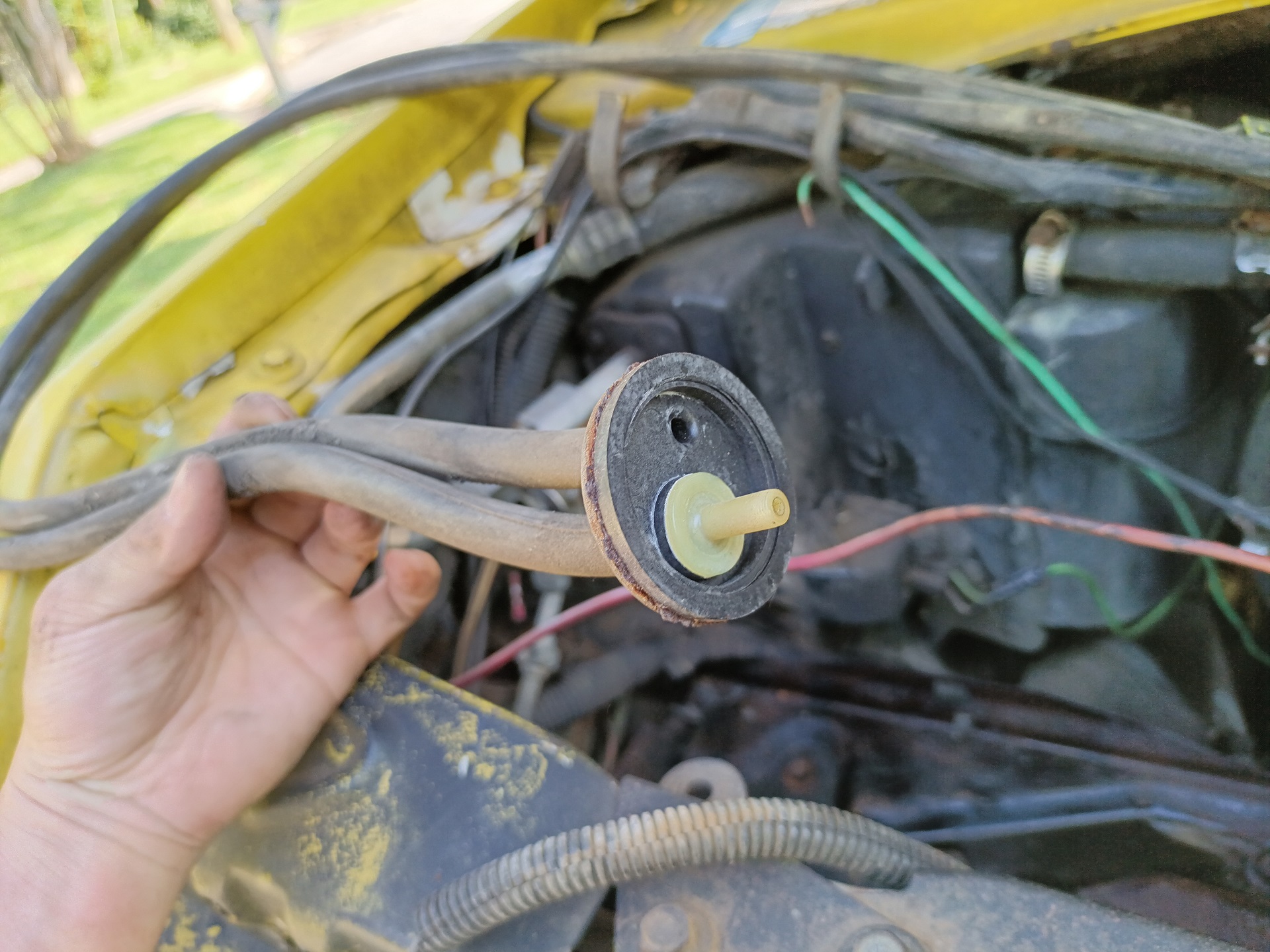
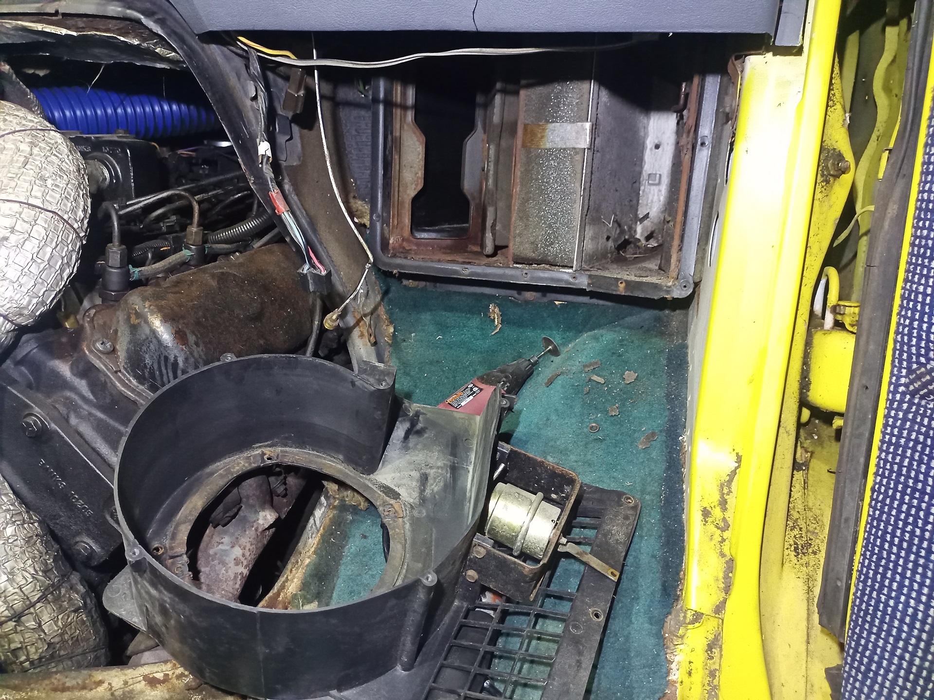
The probably red-hot trailer brake line melted through a bunch of things. The plastic vacuum reservoir serving the power brake and HVAC selector system (as diesel engines do not natively produce manifold vacuum, a vacuum pump hitched to the engine pulls these little bubbles down for stuff like the cruise control actuator and vent selector), basically all of my appended wiring to bring back the overdrive unit and air purge solenoid valve, and a fair bit of the main engine wiring harness.
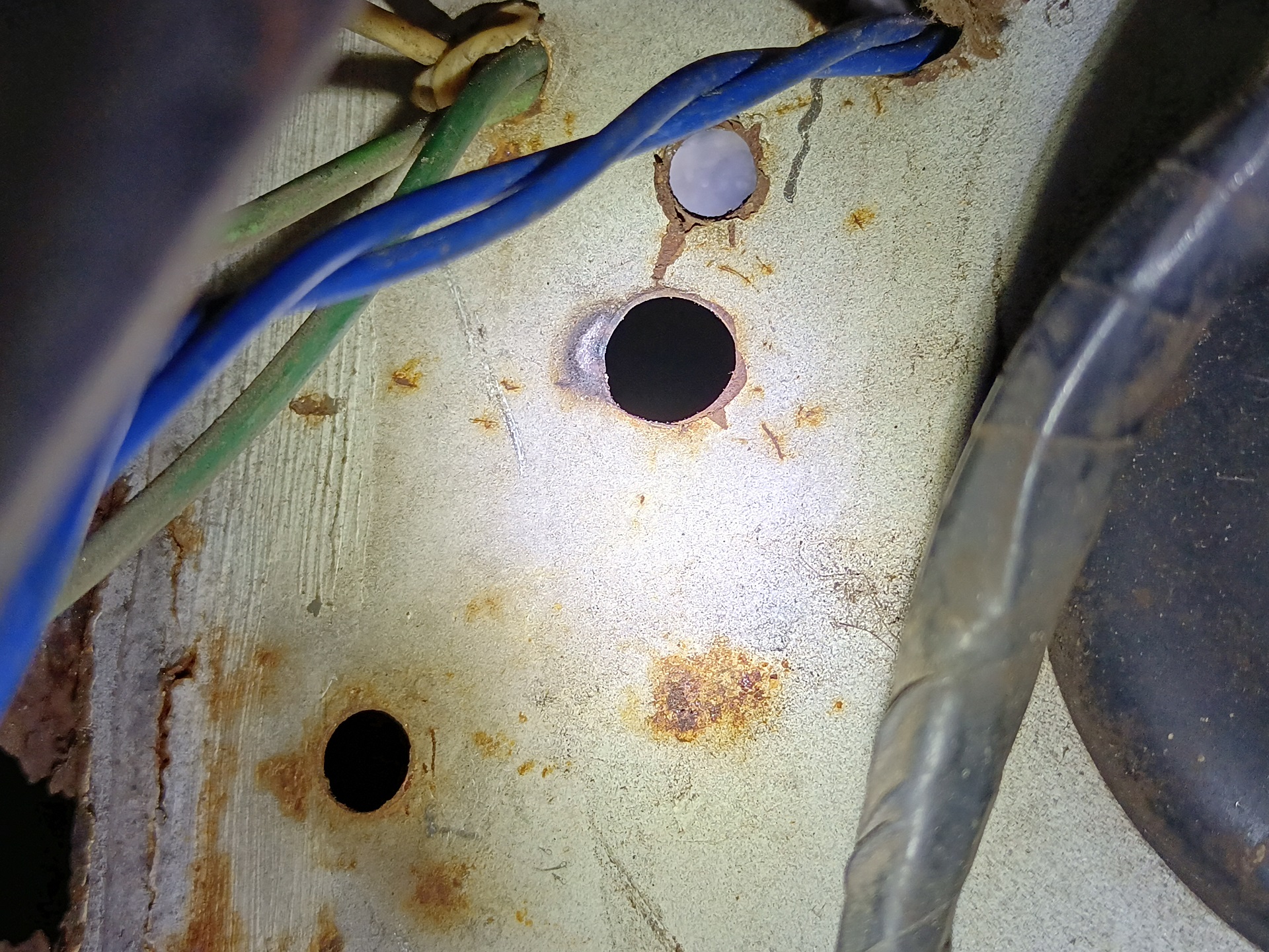
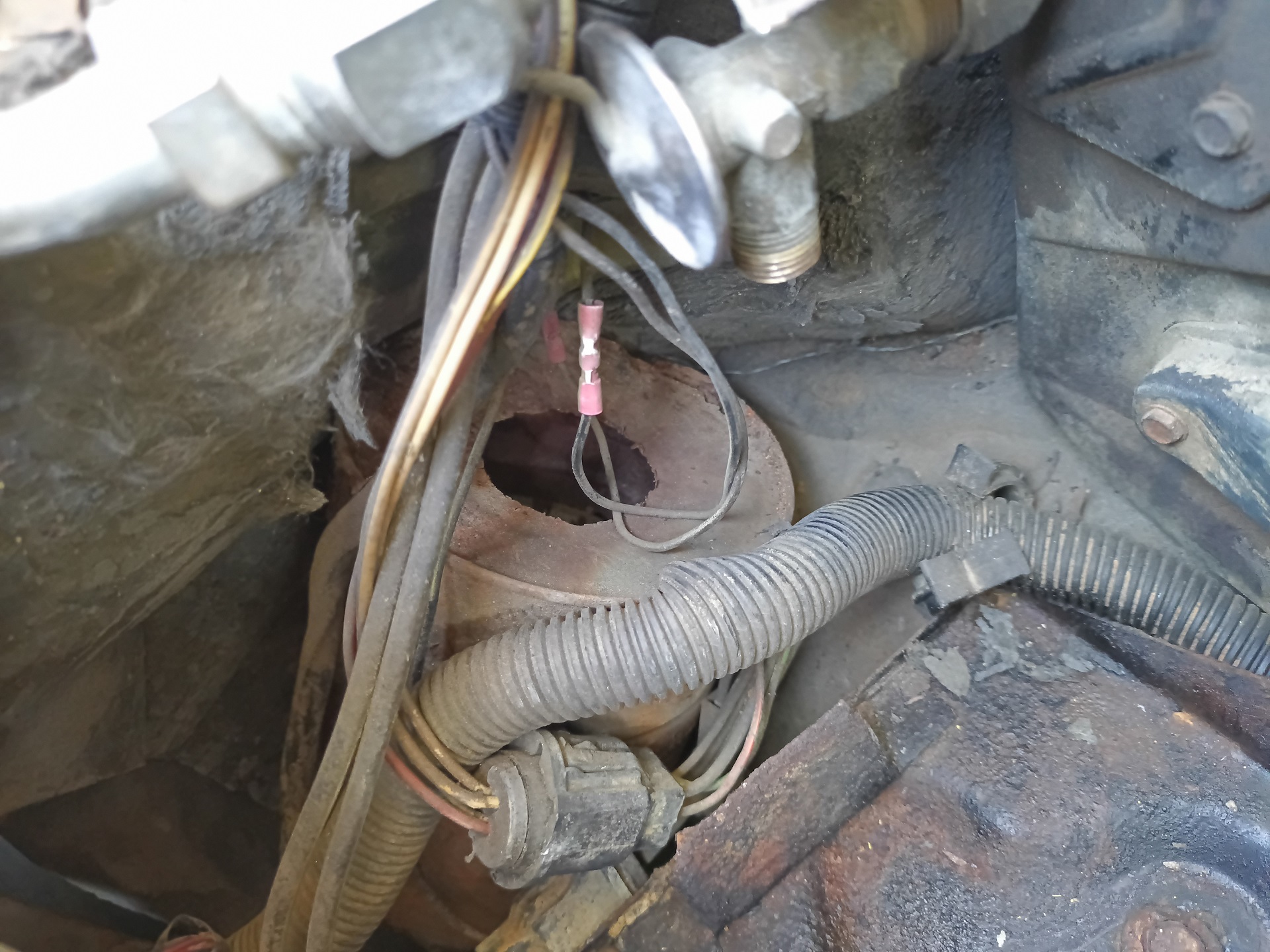
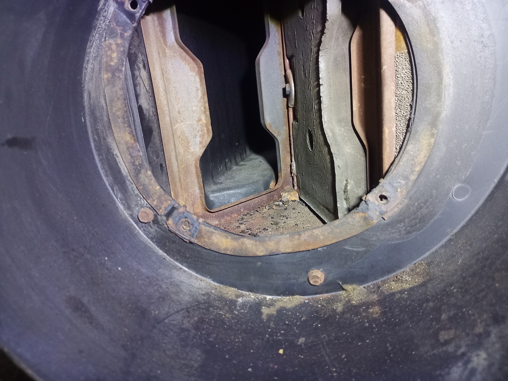
This hole was where the whole thing grounded out. Spool Bus just has a bunch of these random holes drilled into the firewall with random stuff pulled through it, including wires (including some of my wires too so I’m not entirely morally clean, to be fair).
So, in short, Spool Bus was a time bomb on multiple fronts. The battery cable had probably been resting on the trailer brake line for a while, and if that didn’t eat itself, any one of the other wires could have grounded out on the sheet metal and melted. At this point, enough was broken that I basically had to redo a lot of the wires from scratch and replace all the vacuum canisters anyway, so it was time to just commit to taking it offline and doing everything properly.
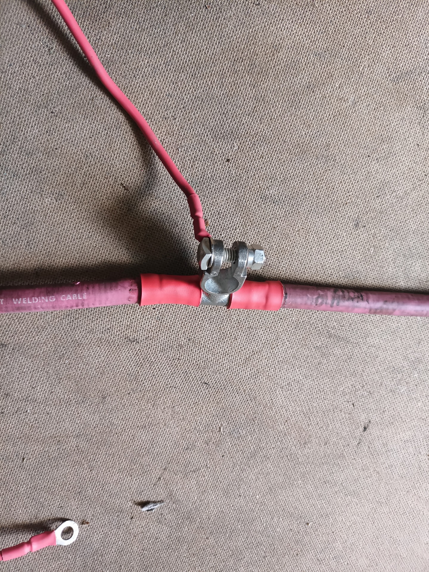
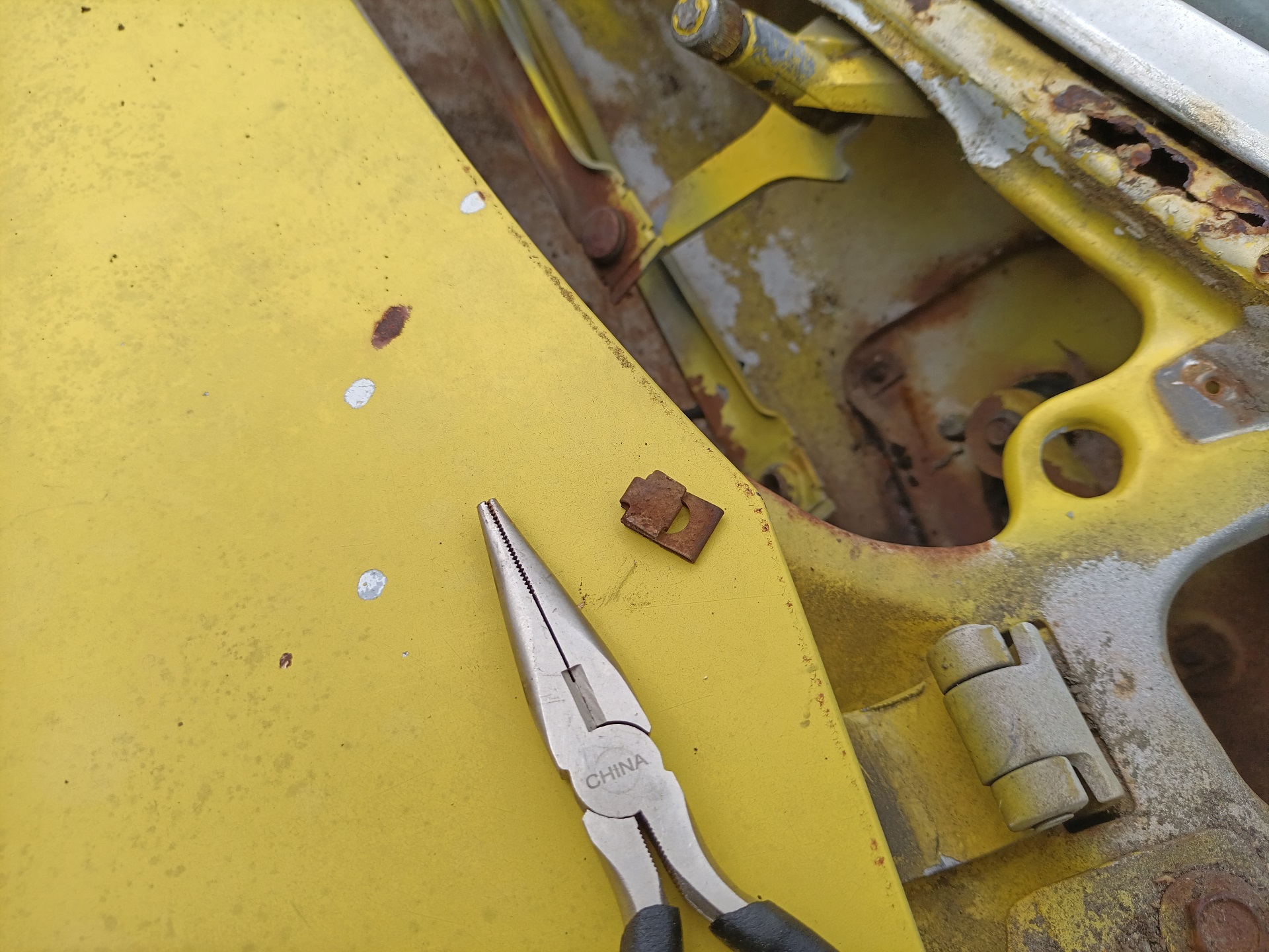
Like look at this battery tee clamp. That’s 30+ years of being bent and pried and hammered back into the right shape, and it was so wallowed out it needed a spacer sleeve. All of this I’d be replacing with new wire and new connectors.
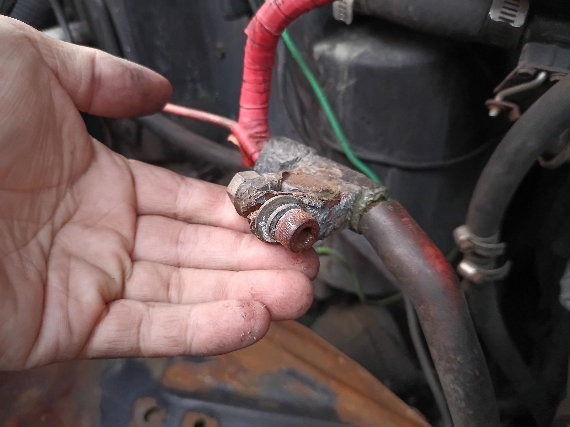
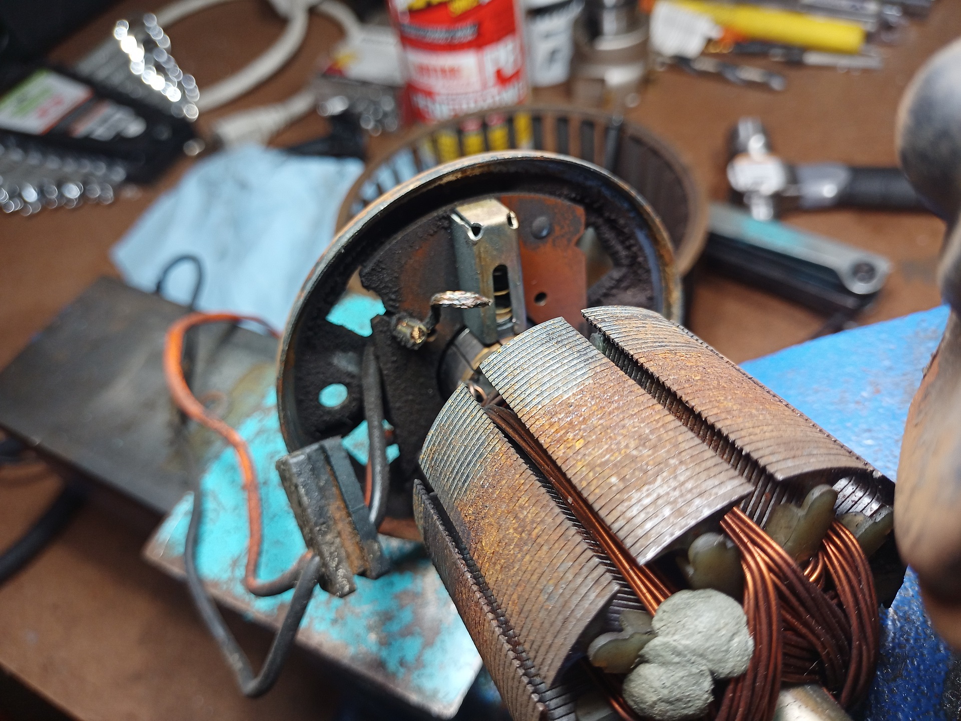
Doing the teardown also uncovered other funny things, such as the fact that this auxiliary vacuum canister had rusted out probably some time into the Clinton administrations. Spool Bus always had a very mediocre brake vacuum assist strength, The fact that one of the vacuum cans is just not (a failure to suck, if you may) could explain a lot.
The diesel chassis came with these extra brake vacuum reservoirs They looked very much like repurposed coffee cans with a fitting attached. No treatment of the metal meant the thing basically crumbled in my hands, and almost every one I’ve encountered in the wild has been the same condition.
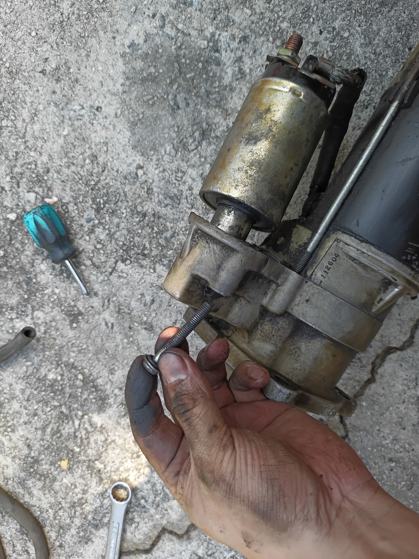
As a random aside, I found out while unbolting the battery cable from the starter motor that one of the bolts holding the solenoid on had fallen out and the other was loose and handing on by 3 threads. Again, something something time bomb how was it even running.
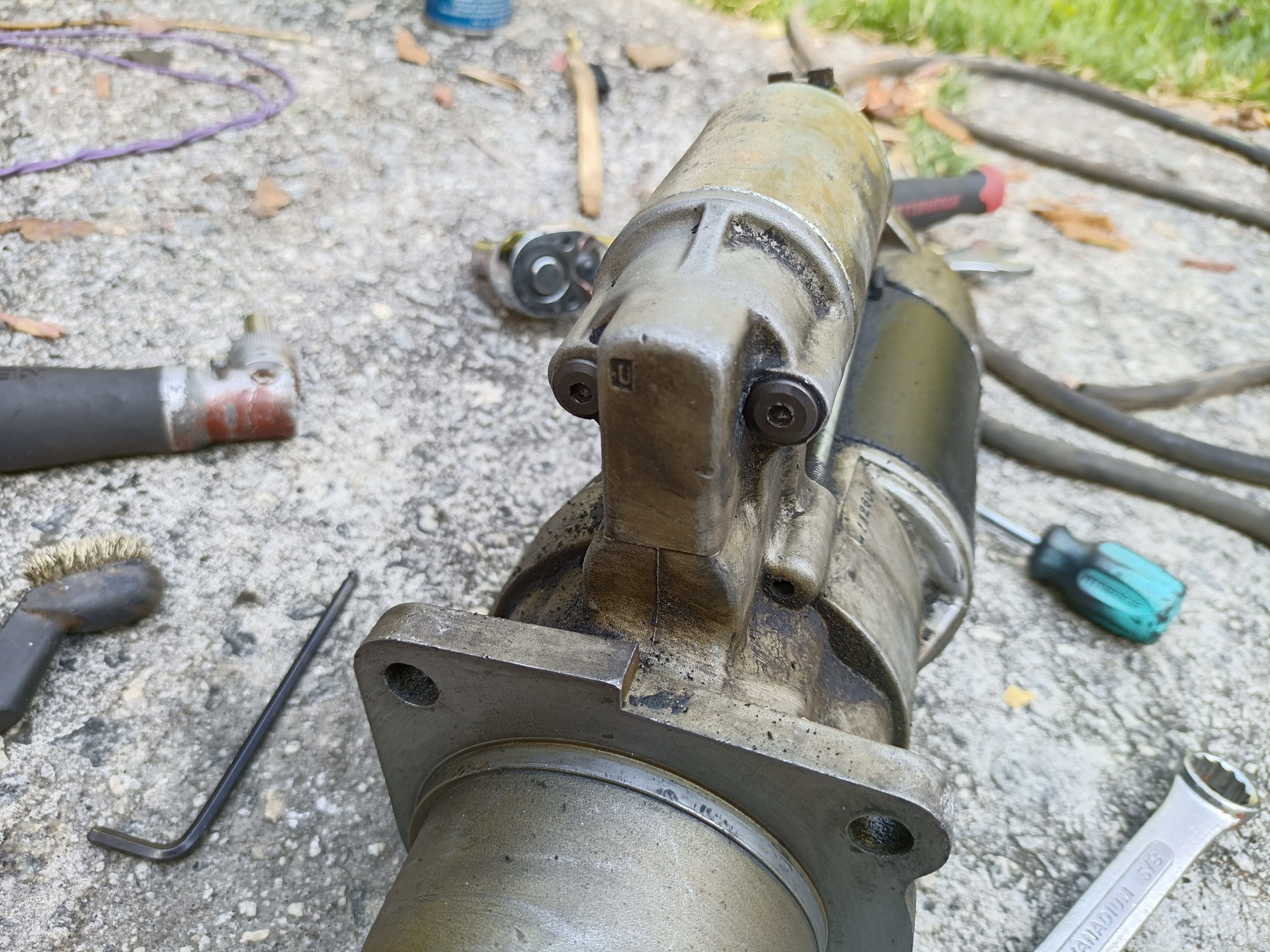
The closest screws I could find that fit were some random ones from a bed frame I took apart. Quality repair!
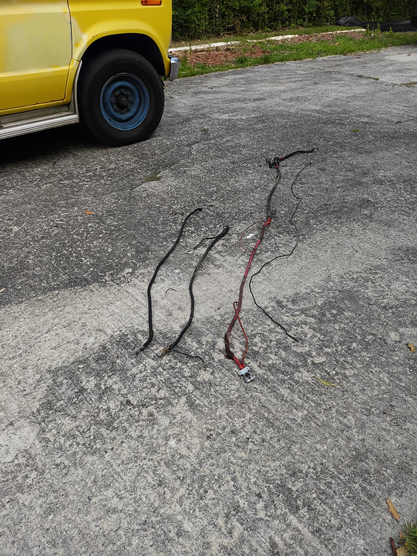
So, to start with, here are the three large wires I had to reproduce. Two battery grounds and the large parallel wire that goes between the two batteries and to the starter motor and glow plug contactor.
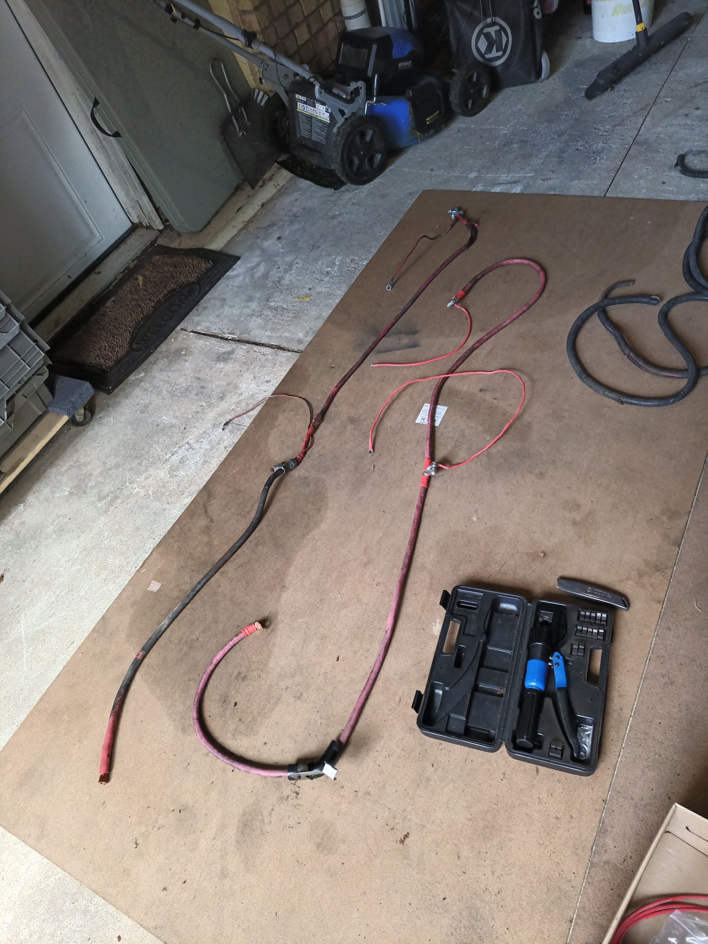
Not a very difficult challenge with my stash of leftover 2/0 size wire, both spare stock from IDIocracy and stuff I harvested elsewhere. I just had to pick up a few crimp-on clamps and ring terminals.
Here’s a view of the new tee junction that goes on the primary battery. It serves the glow plug circuit as well, and has a tap for general vehicle 12V power.
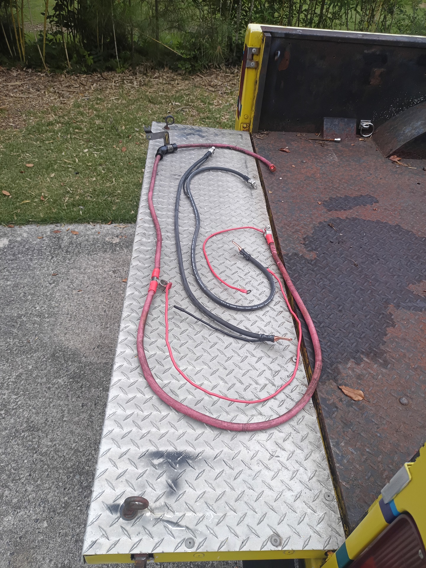
Replacement cables prepared and ready! This was the easy part, honestly. Everything else had to happen before I could install these battery cables. Specifically, I had to replace the master cylinder, run a new trailer brake line into the cabin, and then repair all of the melted accessory wiring. Oh, and replace the vacuum bubble and line that melted too.
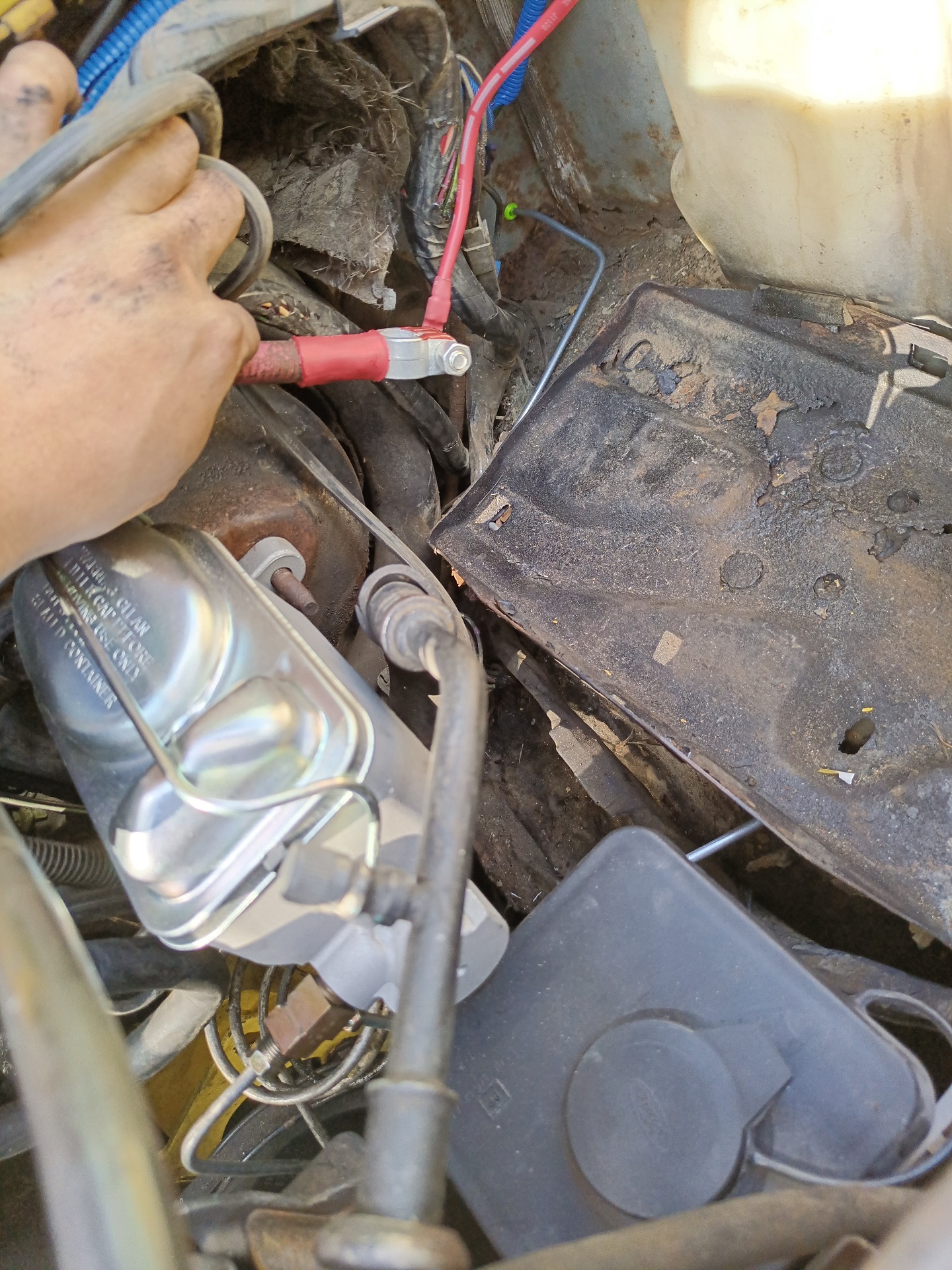
I was never a fan of this kind of old school cast iron master cylinder. I’ve only know them to leak from the lids because the metal rusts and no longer provides a good seal. It turns out they make exact replicas but in aluminum, so that will at least alleviate the rust problem.
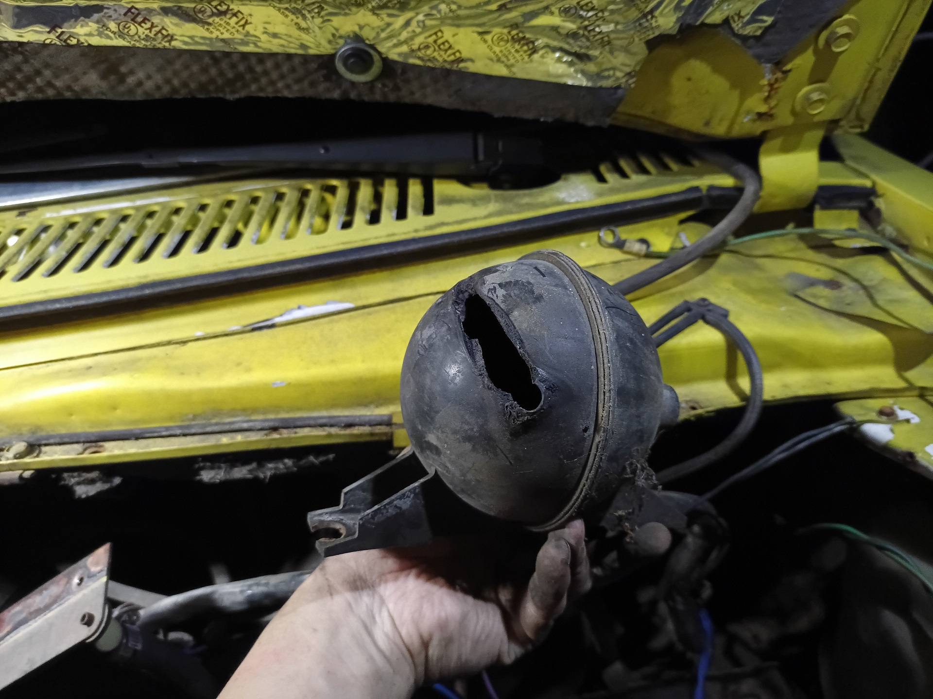
Here’s the wound that the blazing brake line cut into the vacuum reservoir!
I cut back and re-flared the service brake lines because the new master cylinder had different threads in the ports and needed new flare nuts anyway. Not only that, I discovered the fittings had a fair bit of corrosion at the flares too, something you definitely do not want to see.
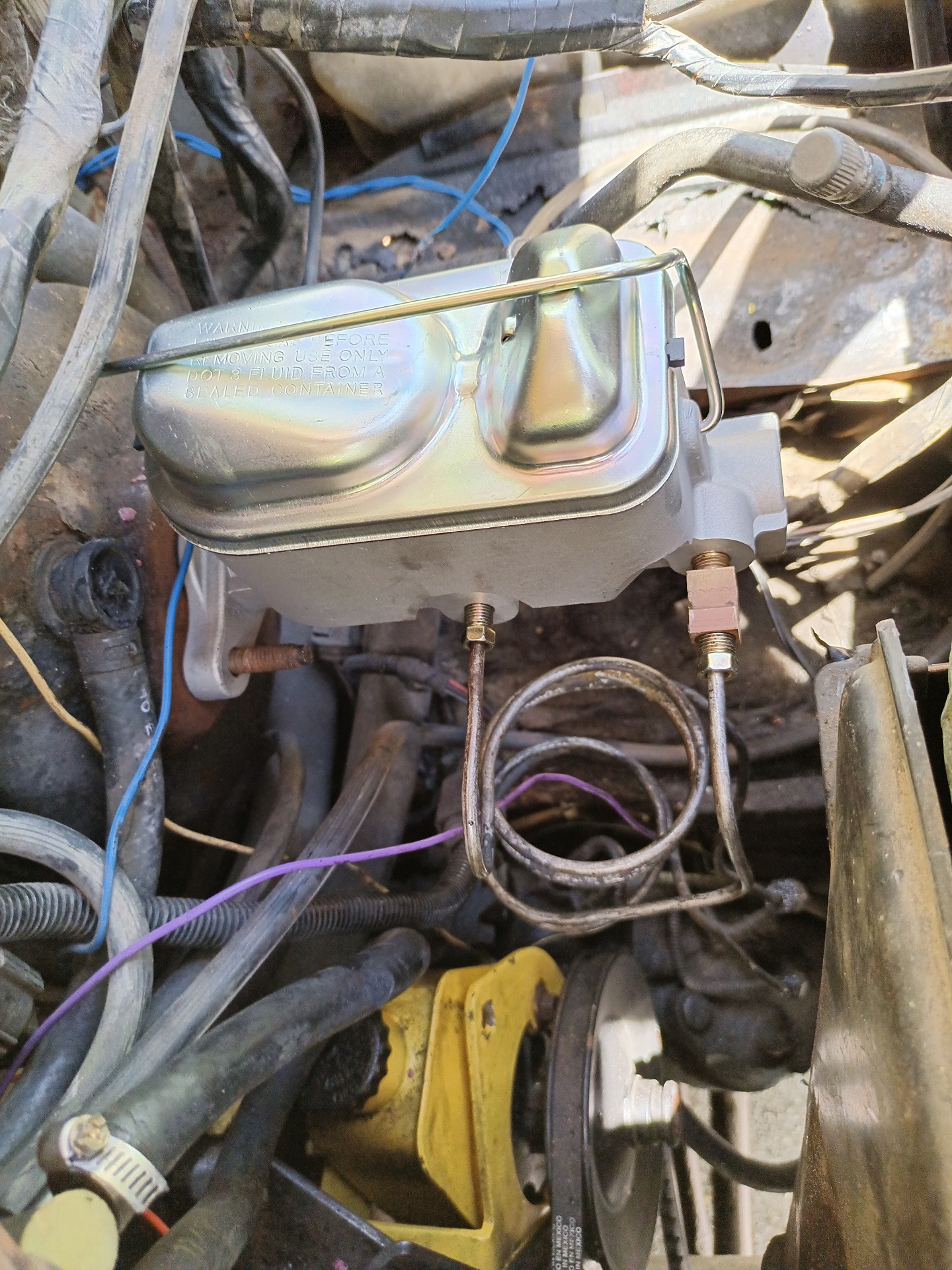
The new aluminum-bodied master cylinder fully installed. The little block on the right is the tee junction where the trailer brake line comes out.
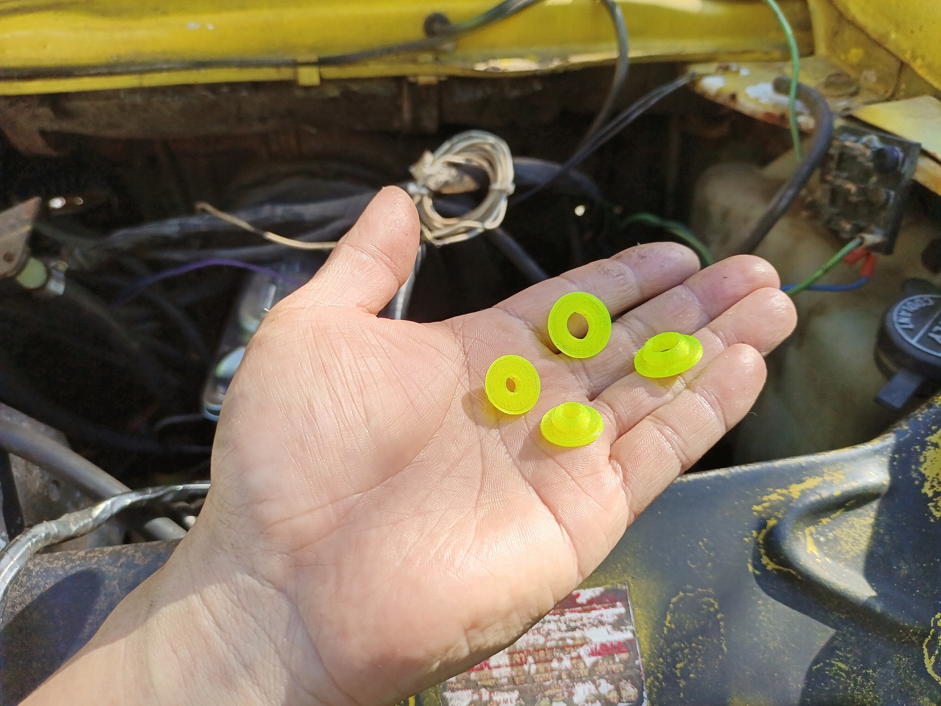
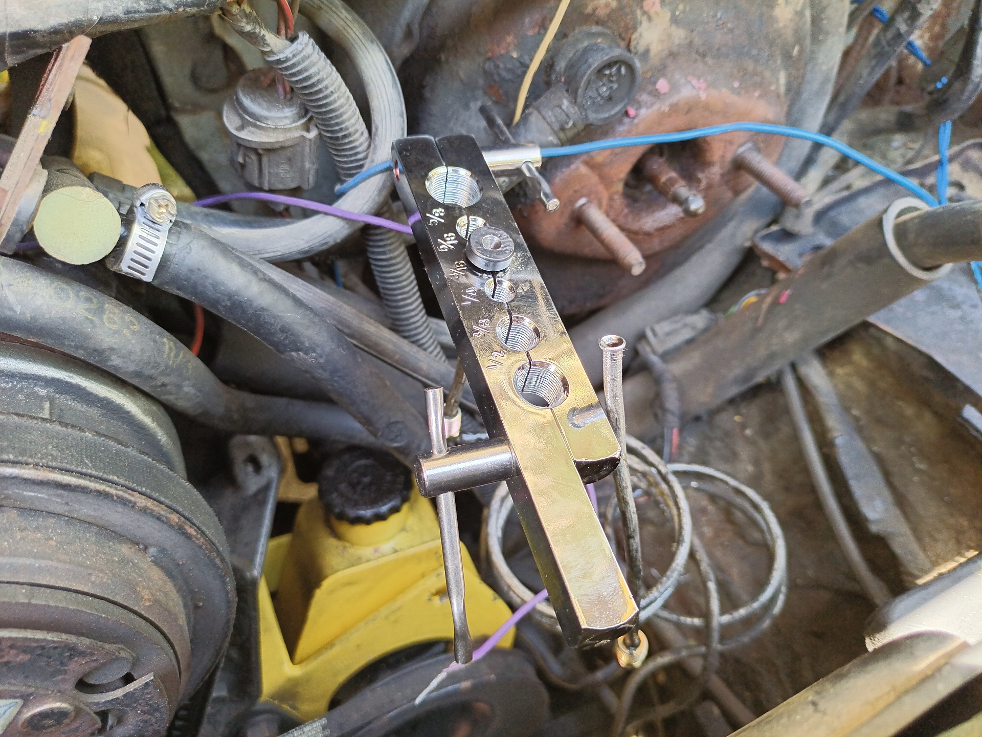
I decided to do something about those infinite “Rust Hole or Drilled Hole?” firewall holes. These are a few different TPU 3D-printed bushings. I cleaned up most of the holes to one of two diameters, 1/2″ or 3/8″, and made press-in bushings to fit.
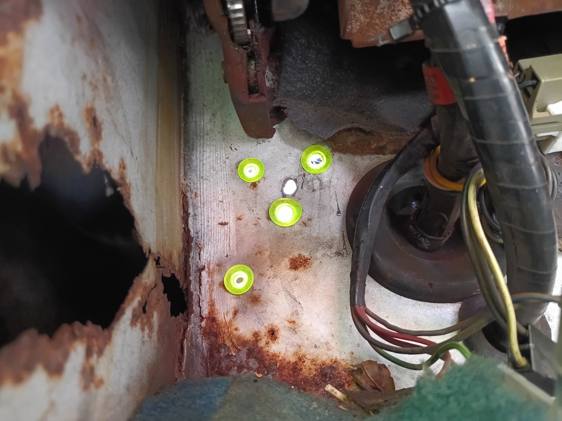
Here’s what they look like! Now I can have my pick of any number of different Rust-Or-Drilled holes to route the replacement accessory wiring through.
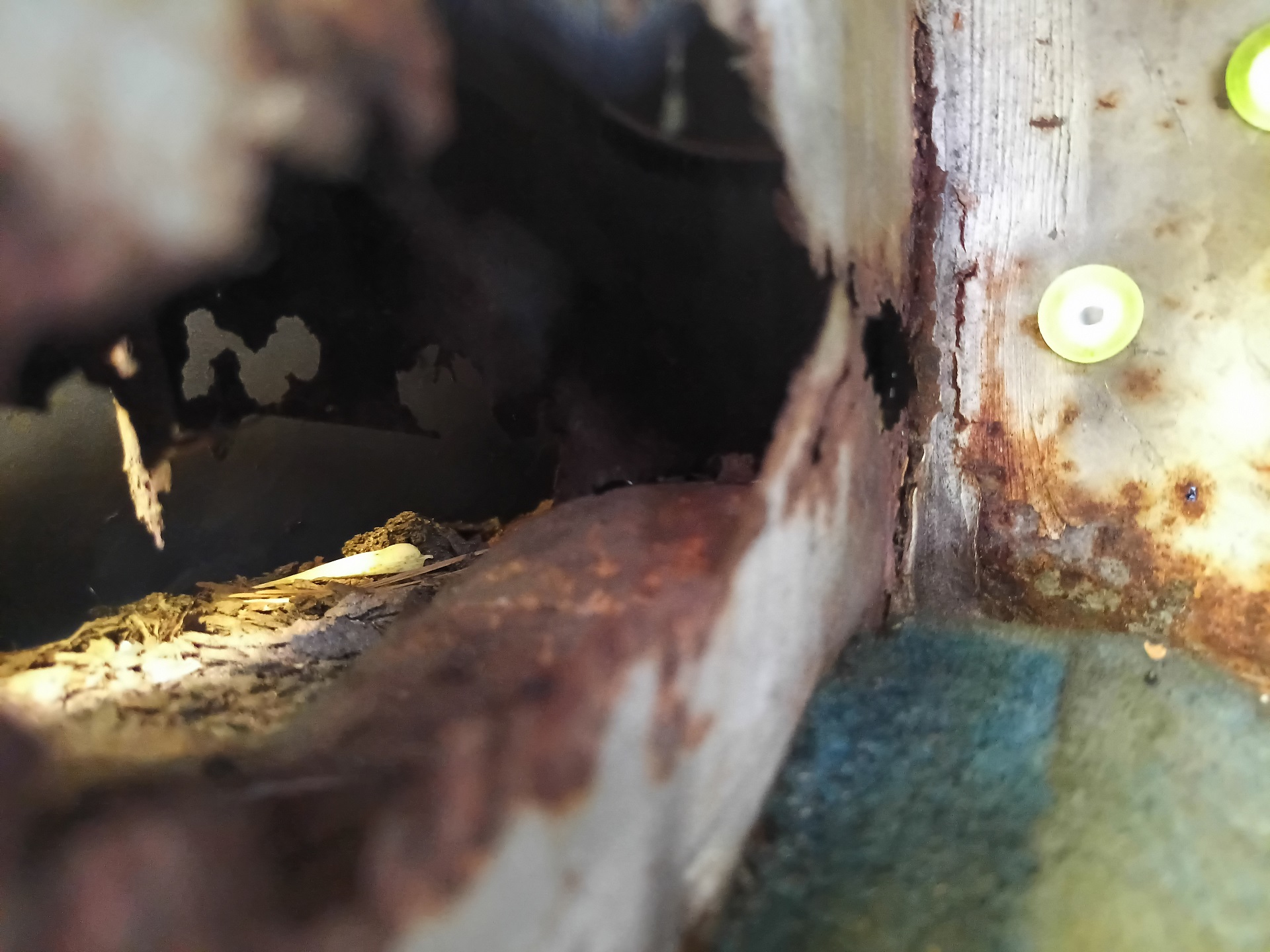
Also, you did NOT see this. There is no massive gaping rust hole entirely through the inner cabin wall and fender apron wall. It definitely does not pour water through here if I drive in the rain. What an absurd concept.

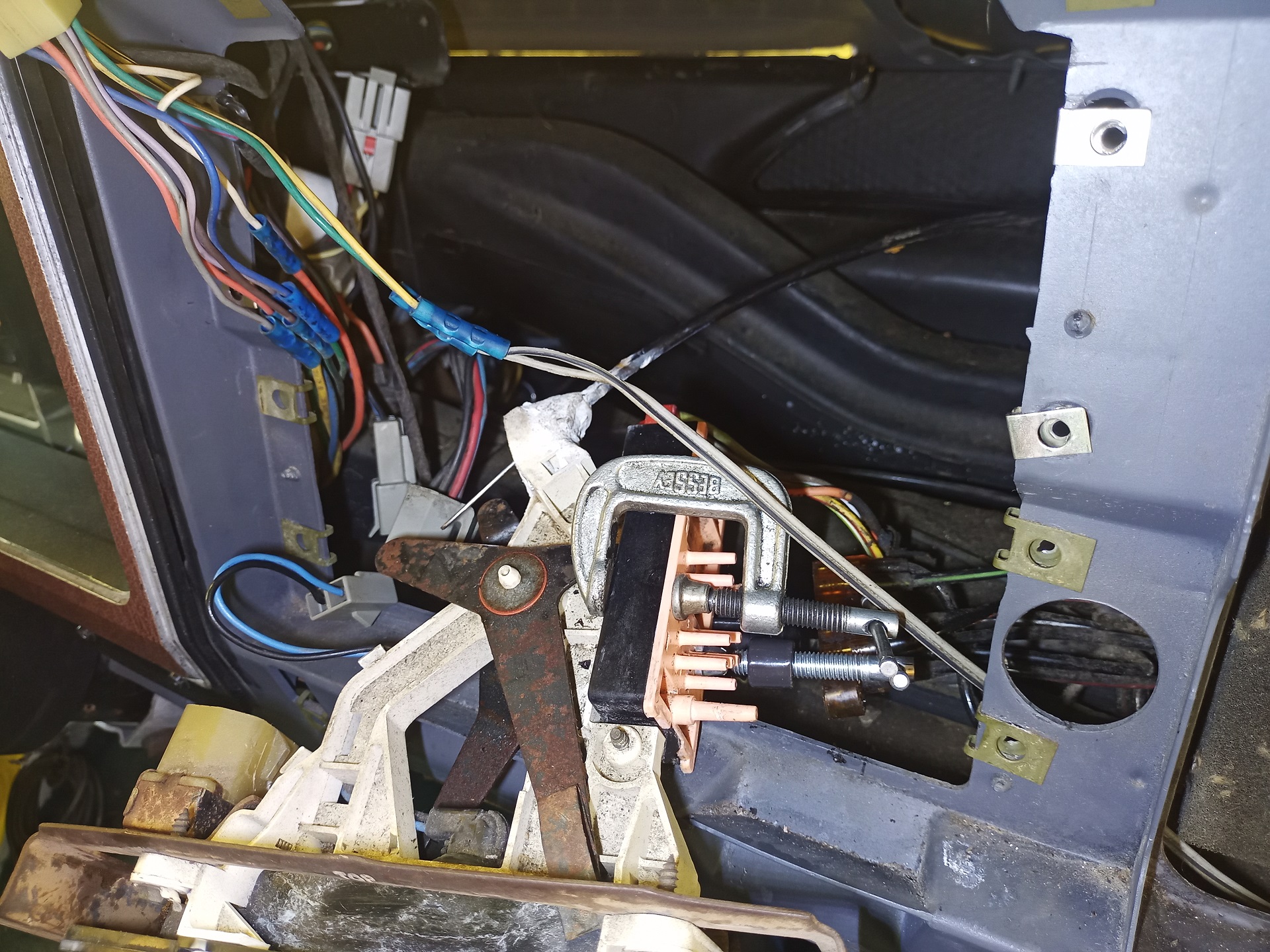
I’m routing the replacement battery cable and OEM engine harness through a large wire loom which will be retained to the upper firewall flange with some straps. This is the same approach I took for Operation IDIocracy in Vantruck. The OEM wiring tray that crosses this area is, by now, always completely deformed, heat-damaged, and otherwise deteriorating.
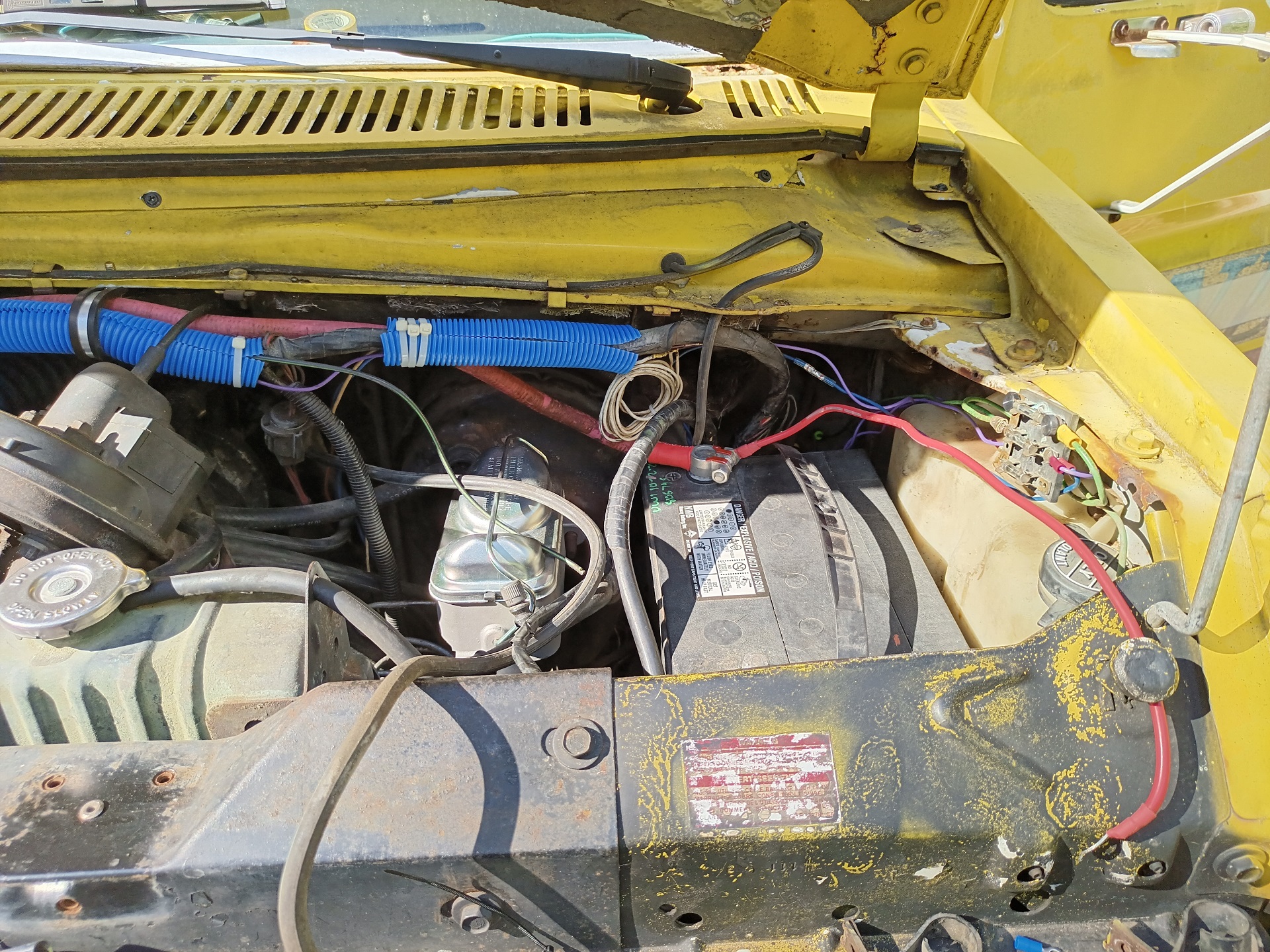
What the driver’s side looks like now with replaced battery cables and hangers.
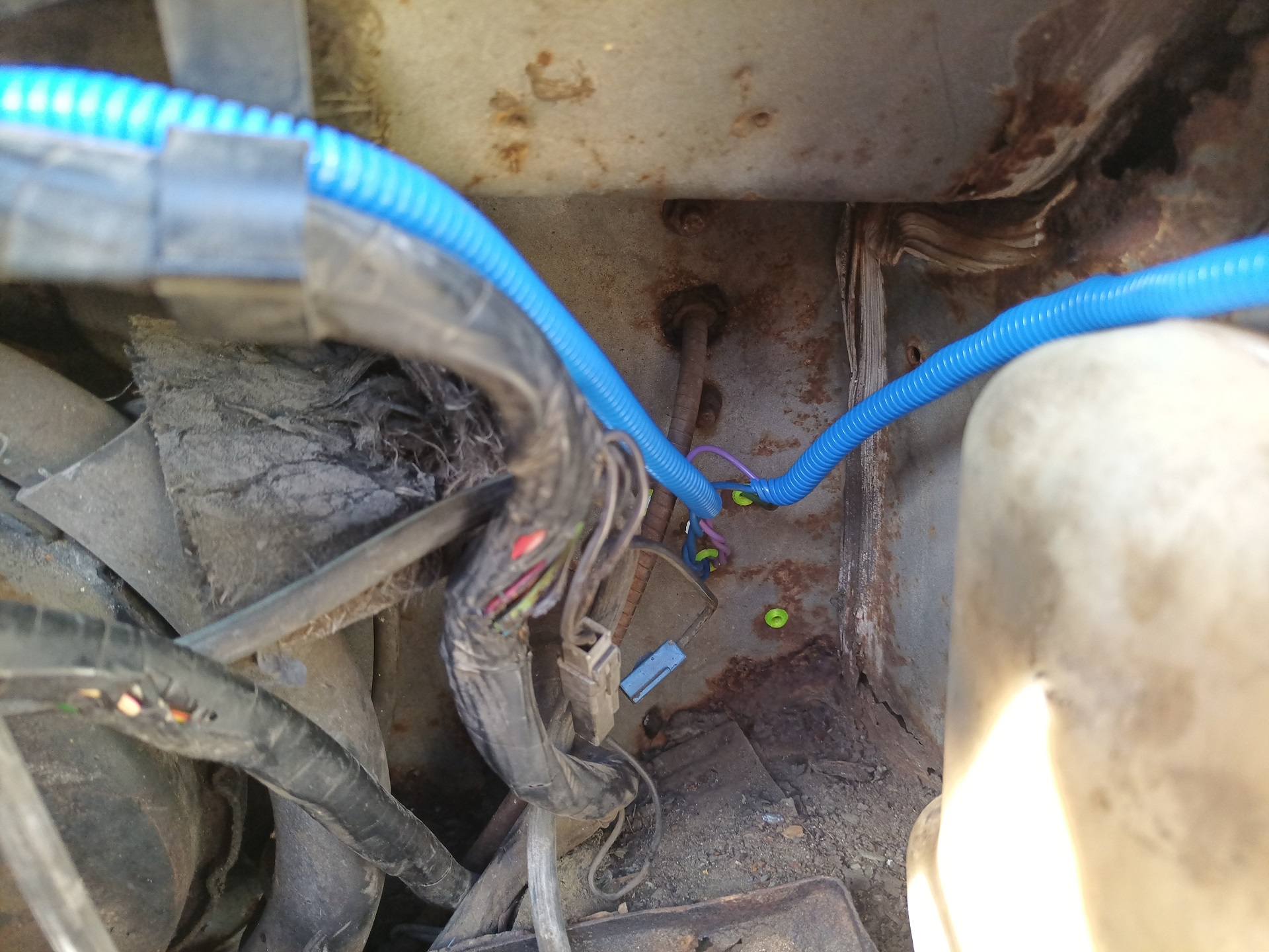
I cut back and re-spliced the two addenda that I put in – the overdrive shifter solenoid and the fuel system air purging solenoid. The new wires live inside looms, and pass through the now protected Random Rust-Or-Drilled holes!
I also cleaned up how the starter wiring climbs up the side of the engine bay, as long as I had everything taken apart.
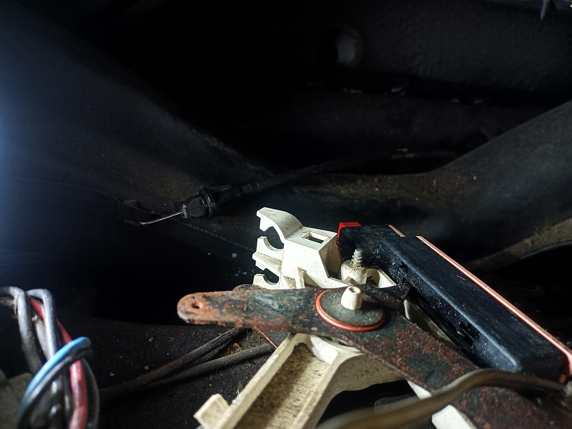
The last operation was to create a trailer brake line that went into the cabin roughly where I needed it. This was done largely using eyeballing a small ruler I held at various orientations to get an idea of where it was going, plus or minus a bit of slop length.
The new trailer brake line runs under the master cylinder and then under the auxiliary battery tray. It should no longer be directly carrying battery current.

It also tees in coming from the bottom, so the whole system will “self fill” if I just keep the master cylinder topped off. I wasn’t sure how you were ever supposed to properly bleed these mechanical trailer brake controllers, because they didn’t have bleed ports. Even if you just left the fitting in them loose and squeezed fluid out with the pedal, the way they’re oriented there would still be an air bubble at the very end! I guess it just didn’t matter enough. The answer to many of my Car Questions about “How did people back then do X” has been “well they just didn’t”
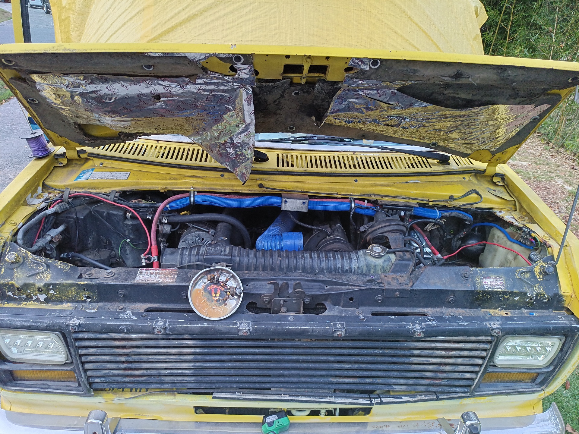
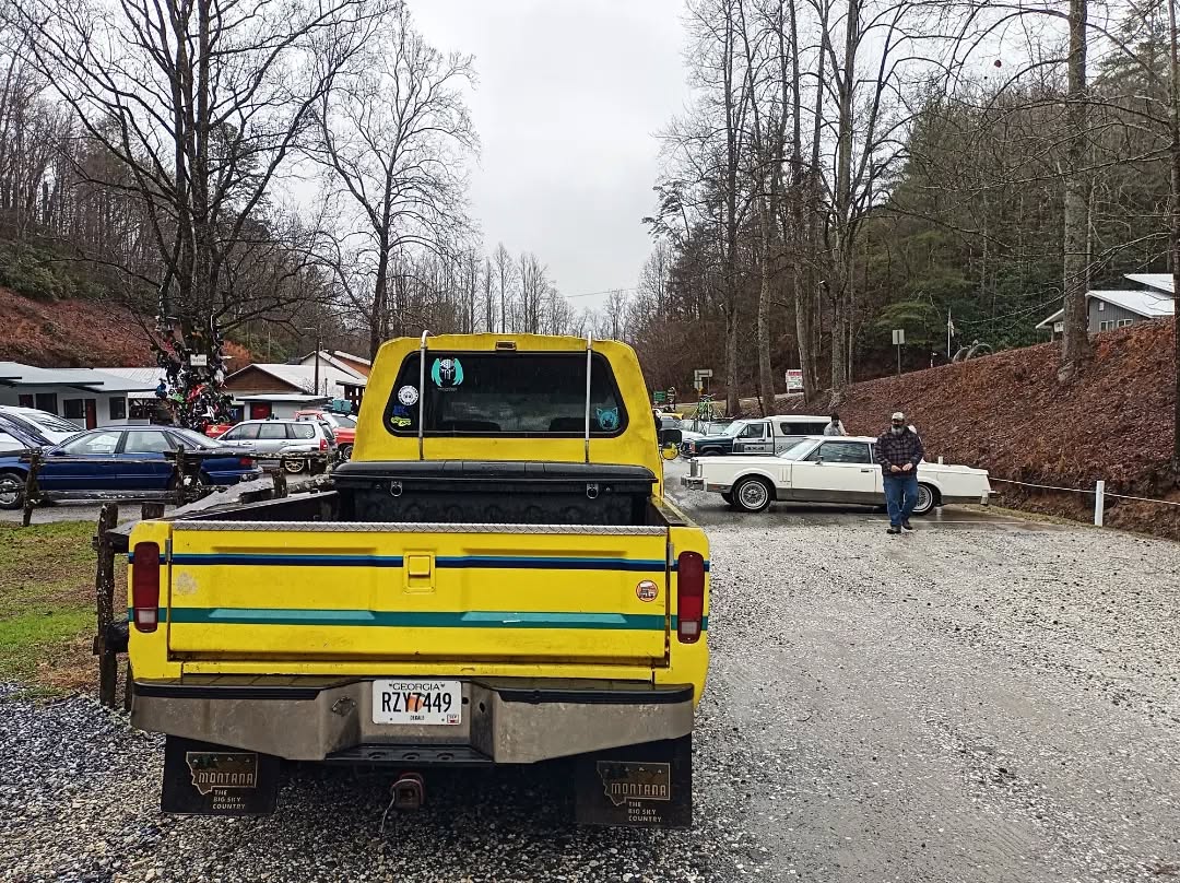
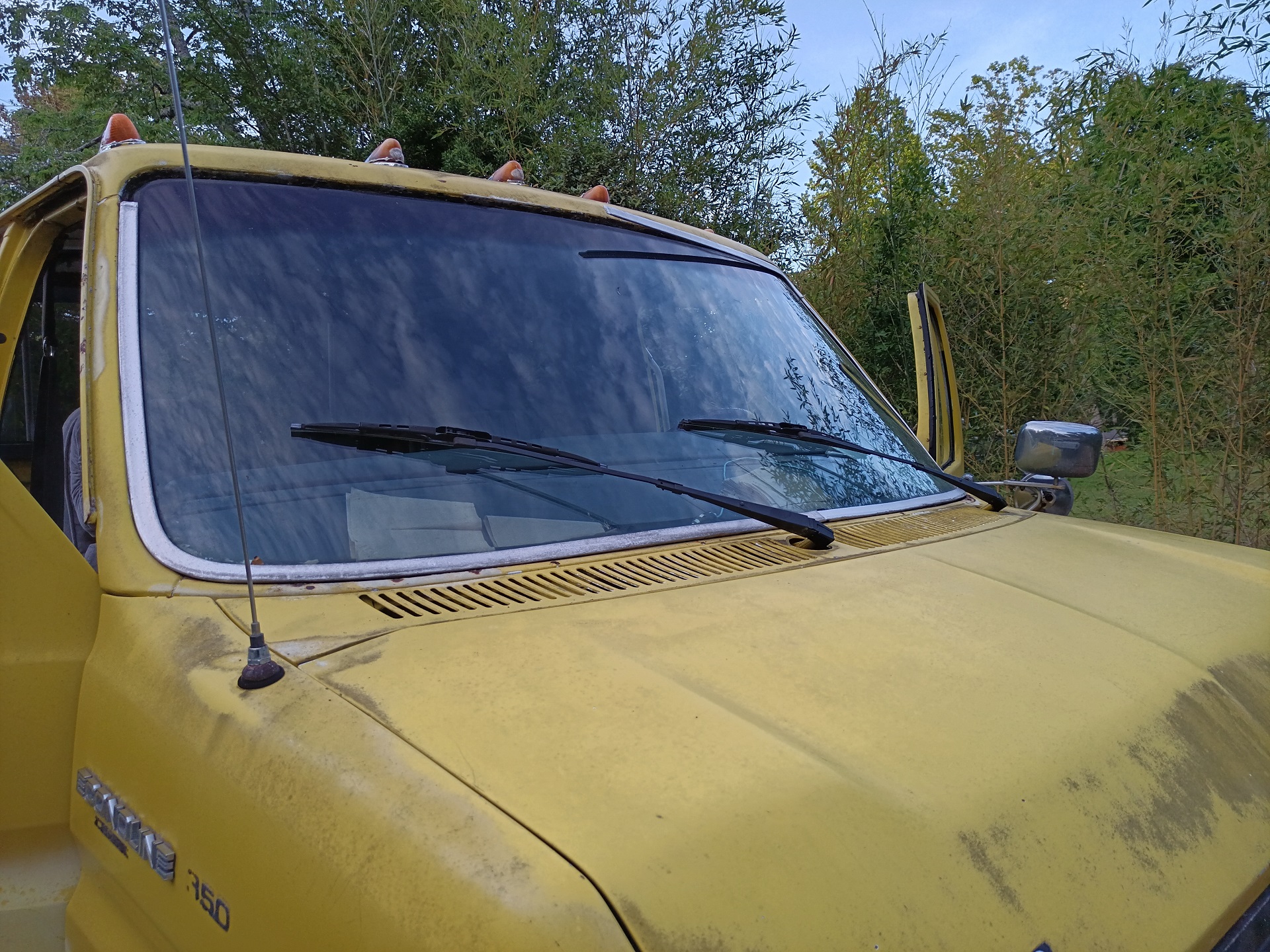
Final closeout time! I fixed the hanging reflective tape, don’t worry.
As I wrapped up the repair on a Friday night, my first inkling was to go get some food to road test it all. I stopped by the local gamer bar (which, sadly, has since closed because the area it’s in is one of those overpriced developer hell projects). I’m proud to say Spool Bus can stop once more, and doesn’t try to MIG weld using brake lines either. Also, in checking over everything on the fuel line side, it turns out the front tank aerating was caused by a giant crack in an old fuel hose I didn’t replace the first time.
Really the only small-but-irritating problem staring at me each time is that the oil pressure gauge itself is broken, or the sensor wiring is broken somewhere inside the dashboard. Spool Bus might still have a ton of stuff wrong with it, but I think by the end of the summer it was at least in the upper 20th percentile of all trucks found in the South: Runs, drives, turns, stops, has lights, has wipers, isn’t profusely leaking one or more fluids, and you can even listen to crazy AM radio hosts. What else do you need really?!