Some time last year, I bought a mill. I then proceeded to drive that mill solely by eye, backlash-riddled dials, and Sharpie marks forever and ever, like I was doing for a while as a plucky undergraduate. While pushing around, on the bench, the DRO kit that I bought not long after the mill. Vacuuming around it, carefully arranging workpieces around the kit, for the better part of a year.
Alright, I’m finally sick of doing that! With the weather being too cold again for me to want to work on the van piles, and Motorama around the corner again, I’m just gonna sit down and bang it all out over a few days. There’s a couple of parts I needed to fab up for the new Susquehanna Boxcar, for instance, not to mention a new 30Haul build (finally)!
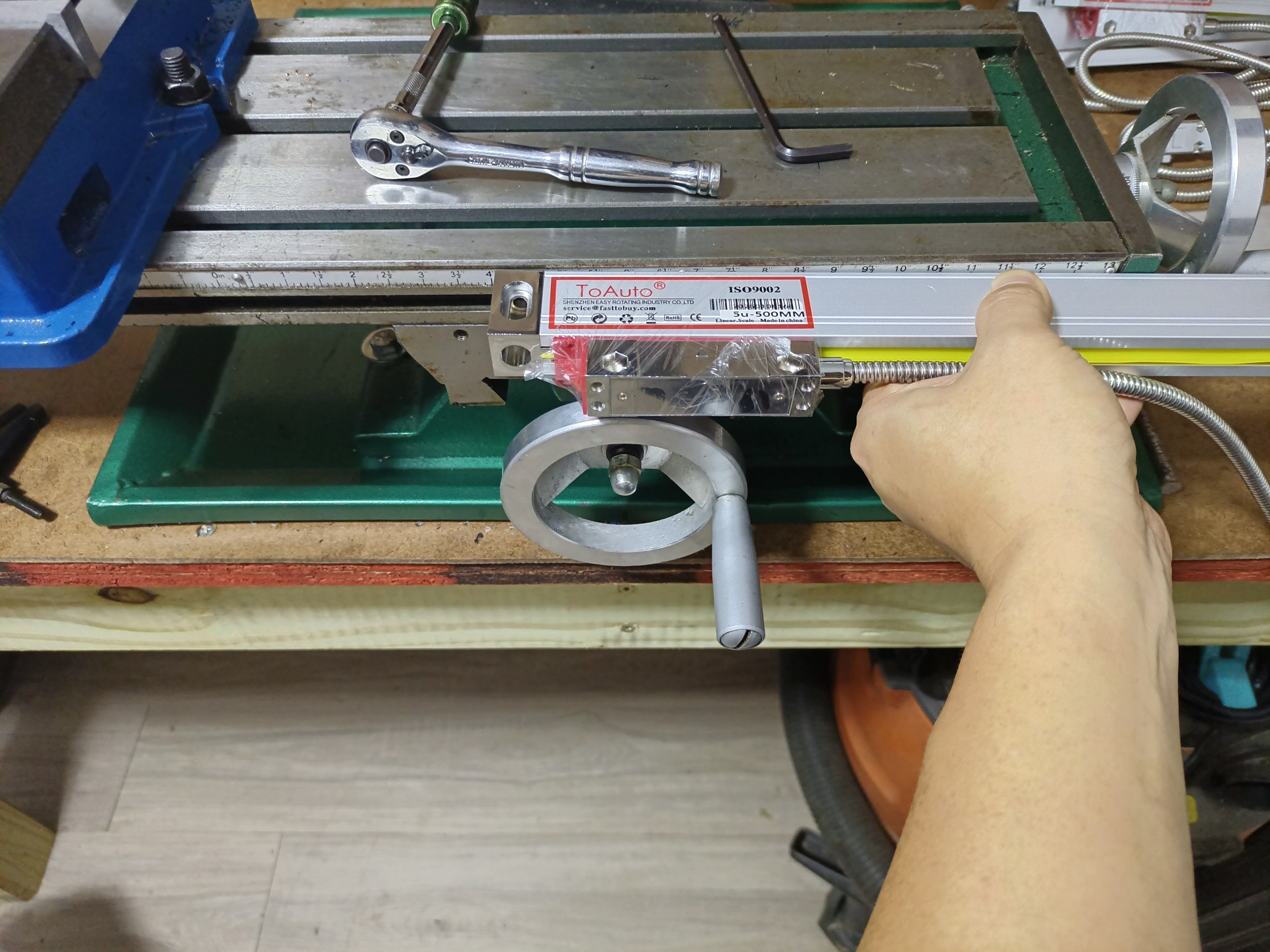
So here’s what we’re looking at. It’s a generic eBay scale kit with display that comes in a few sizes, and I picked two that are a little over the axis travel lengths. I chose to not integrate a Z-axis column readout (the usual 3-axis kit) because the quill has a little readout on it already.
I’m taking the slightly unusual step of mounting the X axis scale on the front of the bed. Usually, you’re supposed to mount them on the back of the bed, but this takes over an inch off the Y-axis travel. On a small machine, I would prefer to retain as much travel as I could.
Instead, I’m going to make some Bracketry to hang it off the front of the bed. I mean, not that ANY of the supplied generic aluminum channel/angle brackets fit this setup, since they are all cut for approximately Bridgeport-sized machines.
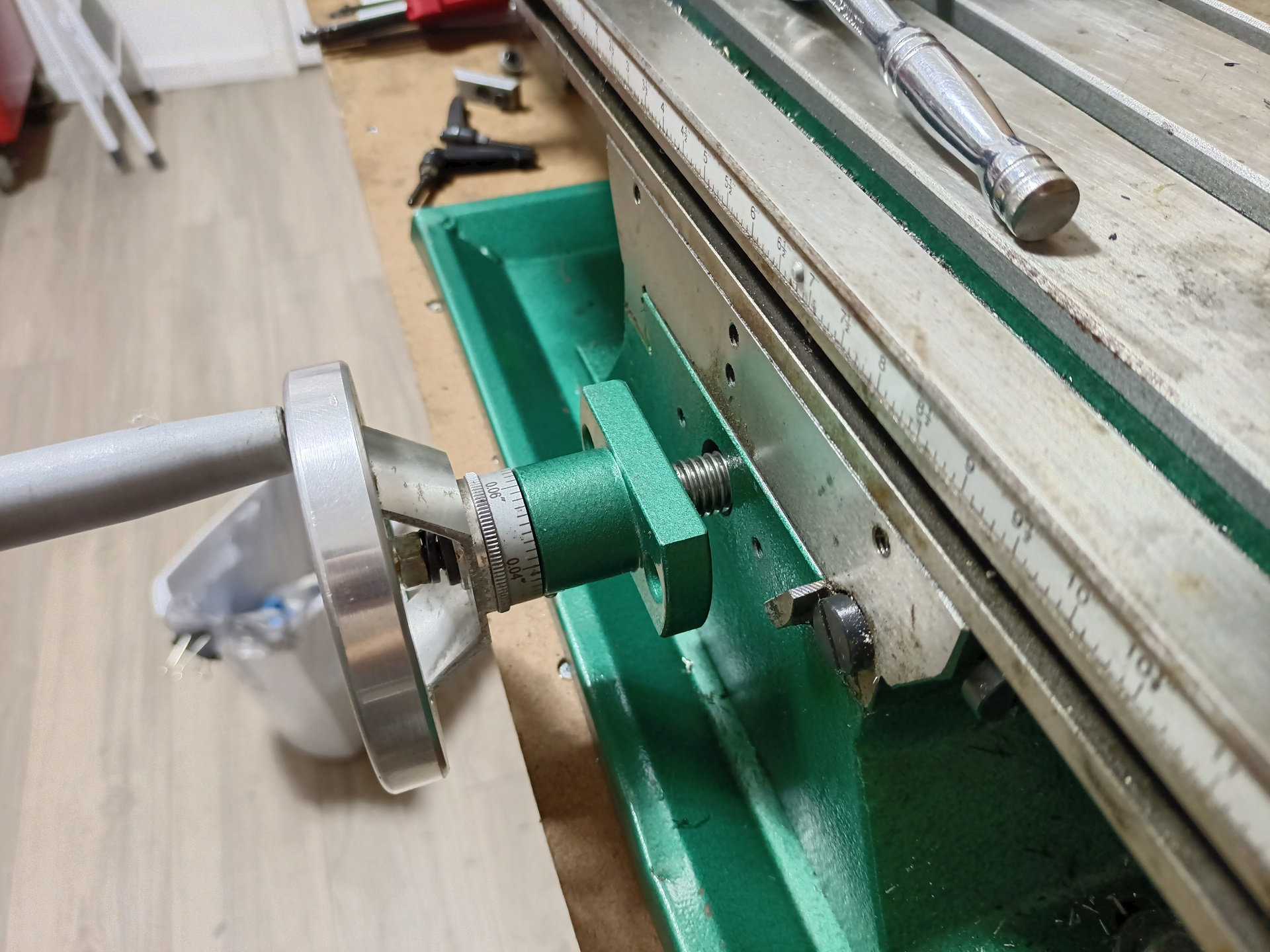
In positioning the scale at the front of the bed, I would have the issue of the scale and slide running into the Y-axis handwheel. But it turns out, you get approximately a free 3/4″ of additional travel simply by unscrewing the leadscrew mounting block from the front of the machine.
This standoff distance is the limit of full axial engagement of the leadscrew nut (mounted to the saddle) when the table is all the way at the back of the machine, so it’s not like at that point I made the thing hang on by one thread pitch. I simply used the extra screw length they already gave you!
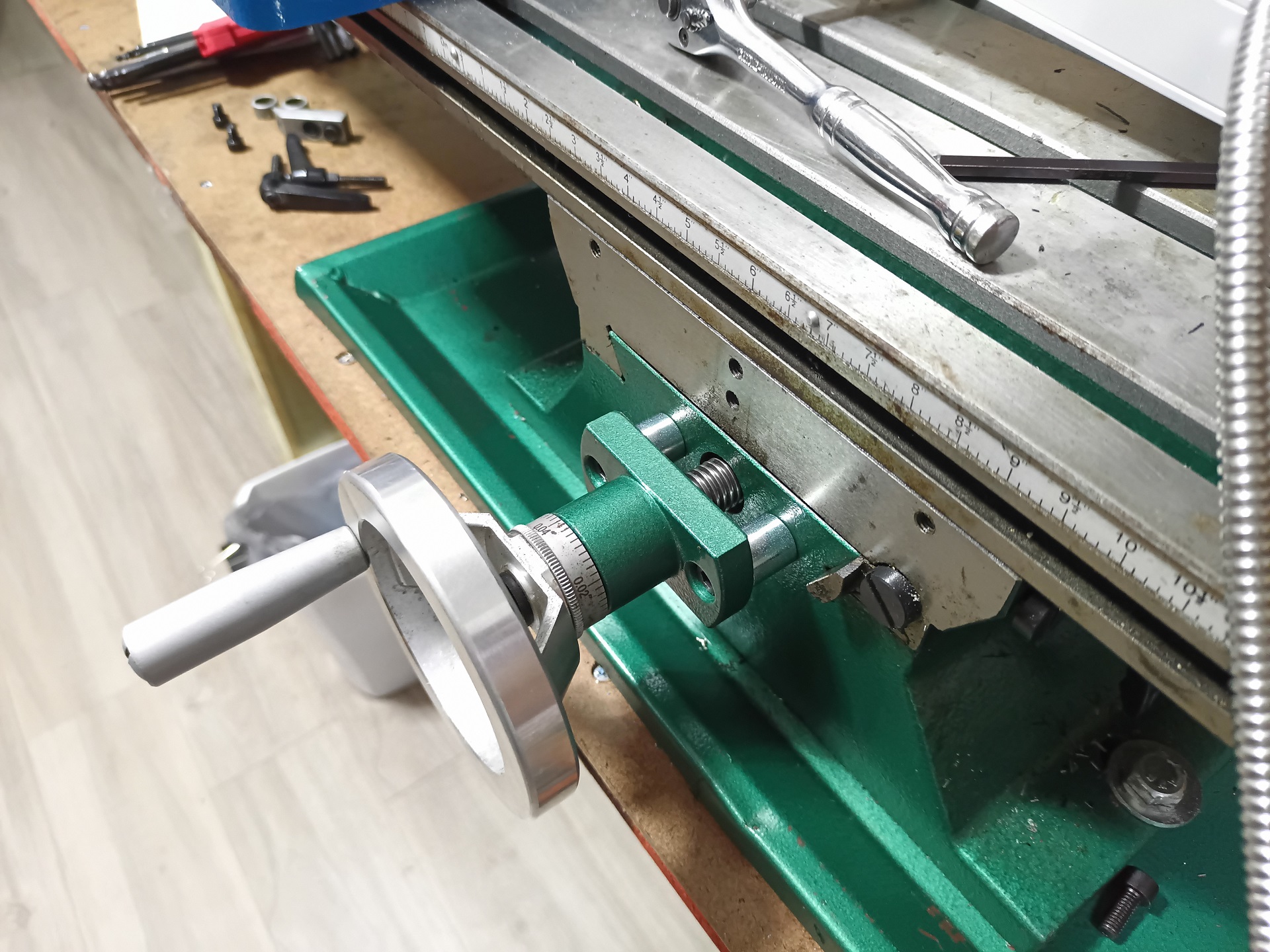
And just like that, an extra 18mm of travel is bought for the price of two steel spacers.
This wasn’t a precision surface here anyway, given that they powder coated it over. The “bonus” travel meant that only the readout slide would overhang the handwheel by a small amount, when the table is fully bottomed out towards the front of the machine, instead of the whole scale mashing into it.
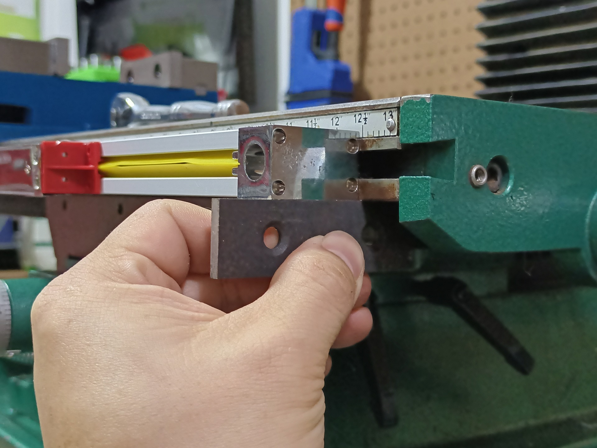
Other than that, installation of the X axis scale was fairly straightforward. I just lined up the bottom of the scale with the bottom of the table. A T-slot nut resides inside the mounting blocks, and the hole is slotted to give about 4mm of vertical slop tuning. It’s going to be a tighten-once affair anyhow.
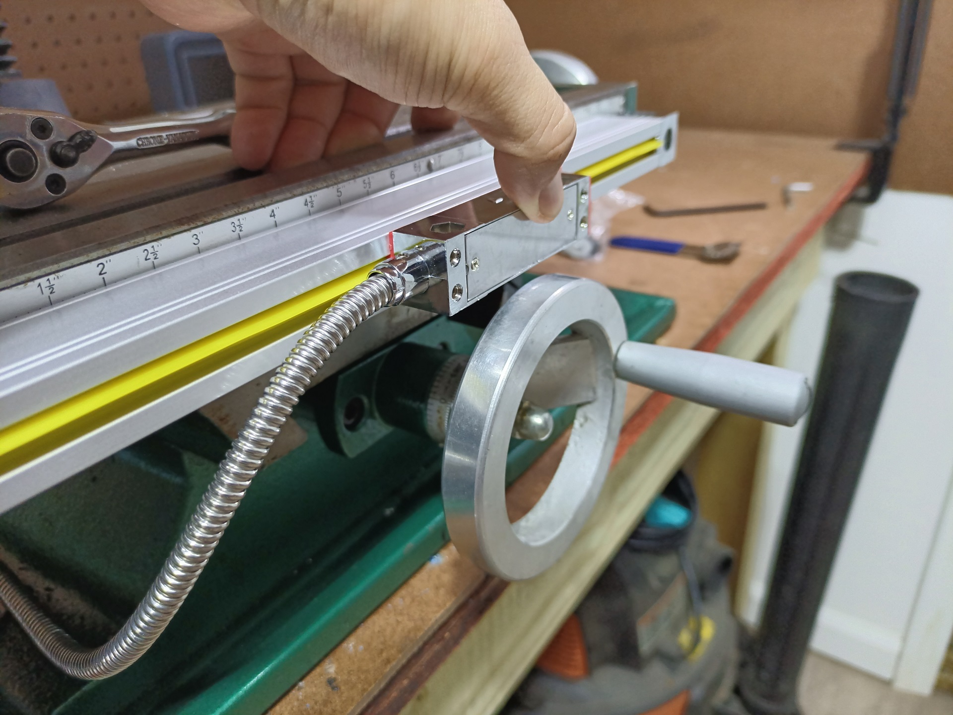
Now I had a solid look at where the slide will end up, and can design a small Bracketry to connect this to the saddle. The gap between the slide and Y-axis handwheel is about 3mm in the center.
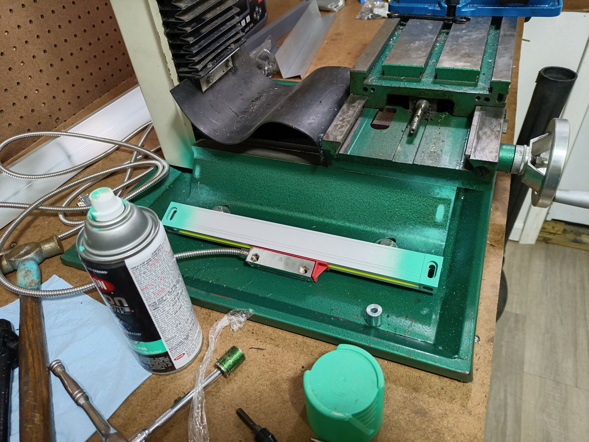
I got a start doing the same kind of size-up operation for the Y-axis scale. This one was going to be pretty awkward. The plan is to mount it at an angle on the side of the machine, but there’s not any good gauging surfaces to line it up. So, with some little welding magnets supporting it and a bubble level on the table surface, I got it to a place I thought would be the most ergonomic to fit up the Bracketry……. and hit the ends with a little bit of spraypaint to transfer the mounting pattern.
I then center-found the paint stains and drilled into the casting. I mean, the slots are there for adjustment, right!? As long as I wasn’t too far off on a length basis, the exact up-and-down placement isn’t too important now.
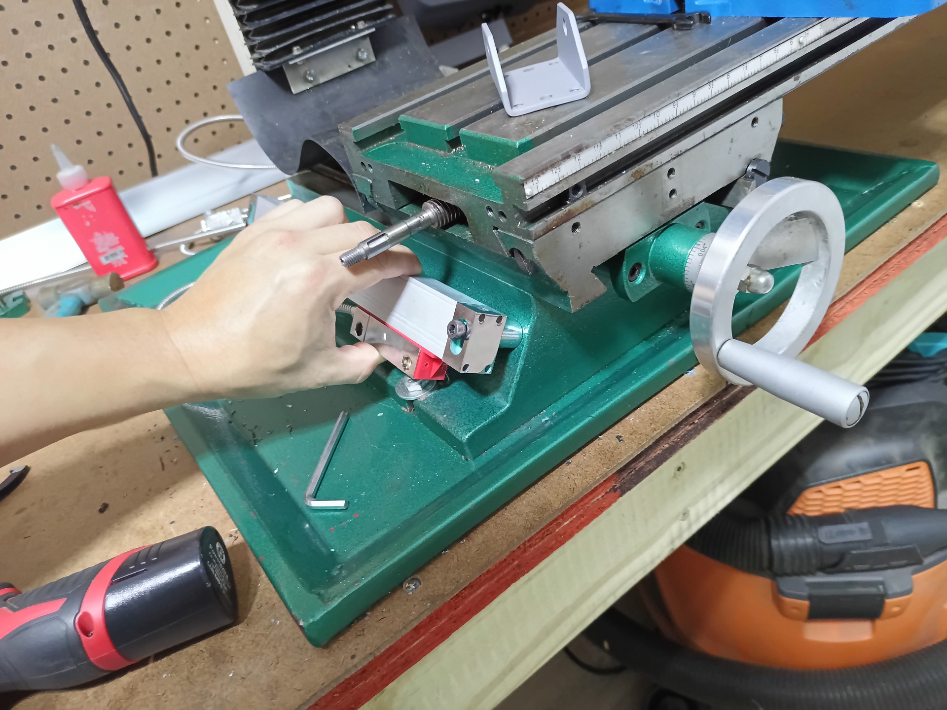
That actually worked way better than I expected. The same 18mm spacers stand off the scale from the machine. Now I had a few good gauging points to work with for making measurements. Usually, DRO slides are mounted with some thin, (relatively) flexible metal leaves and brackets to not transfer much force along the scales. I was just going to selectively 3D print them, so they’ll be inherently a little flexible.
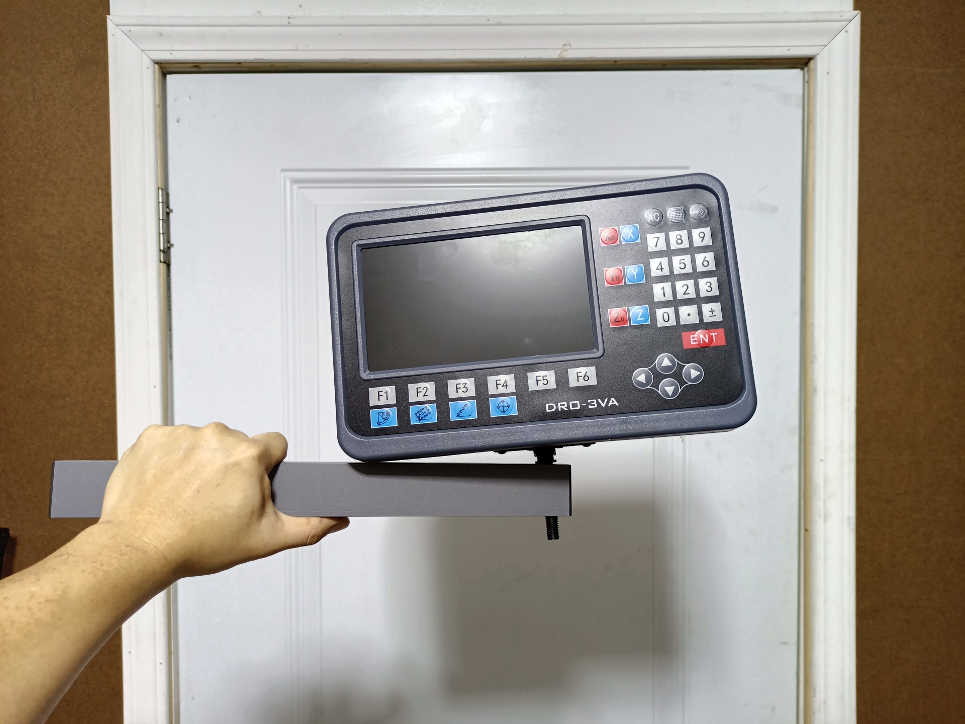
I moved onto doing the rest of the machine setup and oh my goodness you guys didn’t even TRY to line this up. I was legitimately unsure if the arm was meant to be mounted at some awkward angle, but ultimately I think these holes were supposed to line up…
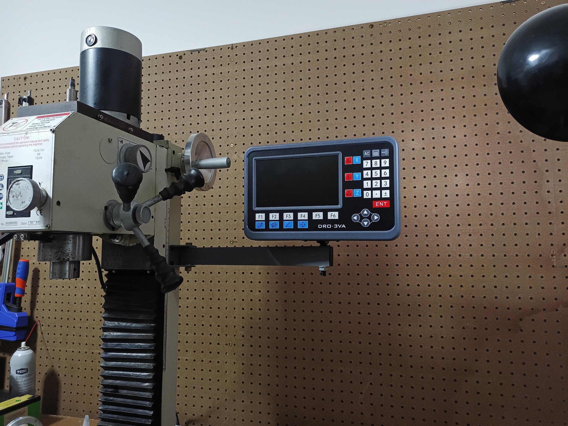
Nothing a little force on the drill press can’t accomplish. The arm mountnig bracket is also drilled and tapped into the column casting.
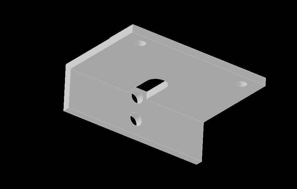
Now onto the Bracketry! Here is the proto-form of the X-axis slide bracket, made entirely to measured dimensions. The two mounting holes natively exist on the machine; they were to mount a little stopper/pointer at the center of the saddle. I’m just hijacking them to mount the readout slide.
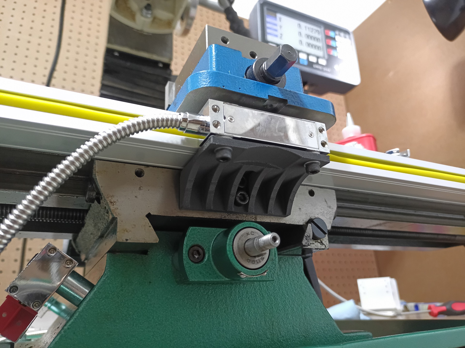
With a little more prodding and an afternoon print using carbon fiber filled nylon, the test fitup went very successfully! I didn’t really need to make any changes at all here. Notice the shim washers between the slide body and the bracket. I purchased washers of the right thickness to make up the thickness difference between the slide and the scale. I suppose they could have been “printed in” but I wanted the fine tuning.
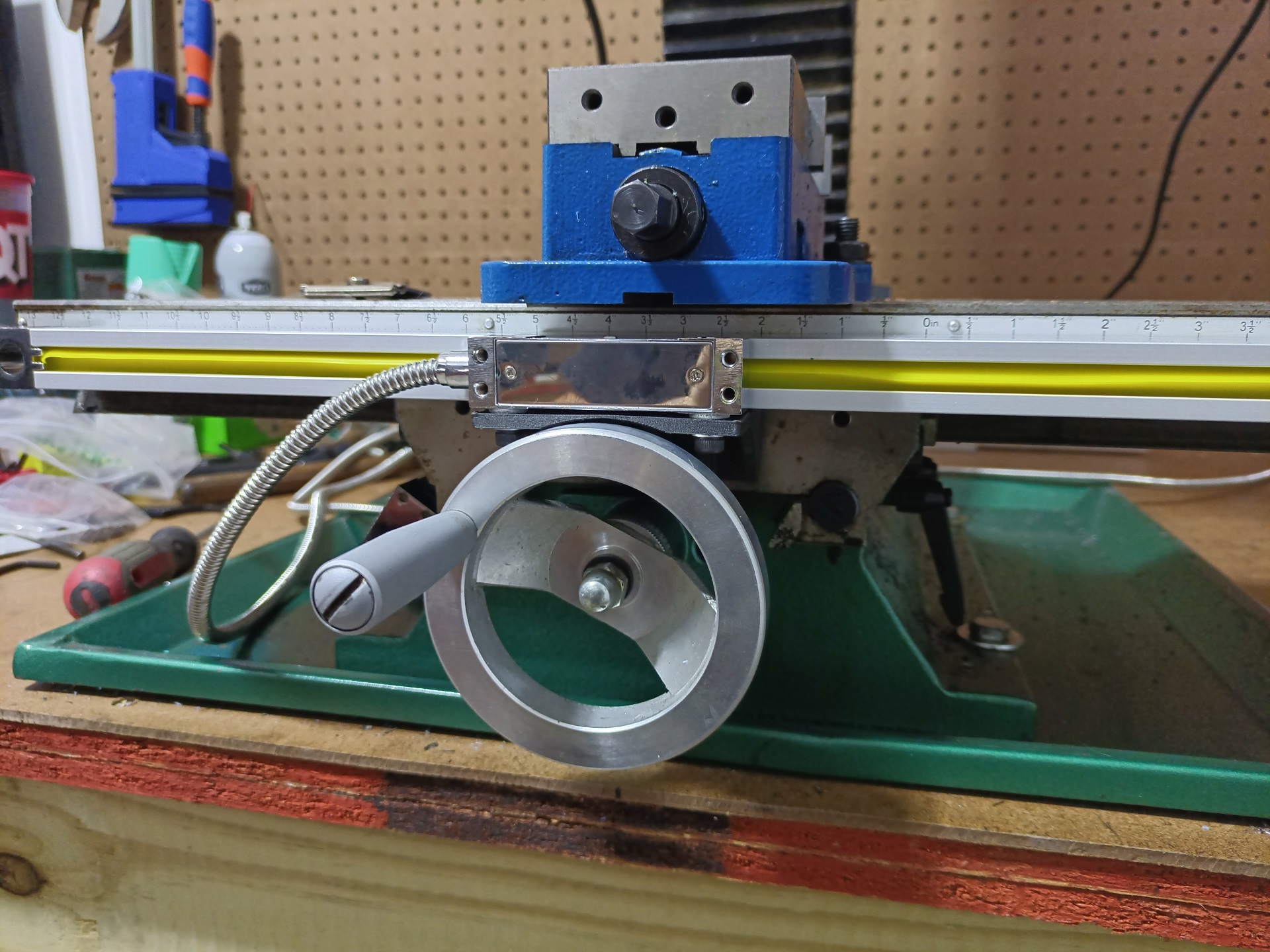
And here is the finished X-axis scale. The table is shown at its maximum travel towards me, so as promised, the slide overhangs the handle just a tiny bit, but is accommodate by the cutout in the Bracketry.
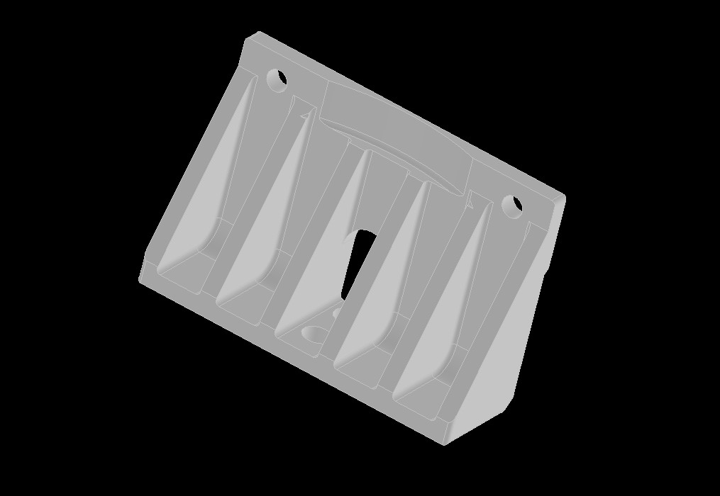
I later went back and made a second revision to add a little more rigidity. I remade this using the same CF Nylon, but added a post-print heat treat to increase its rigidity even more. I’m highly confident this is at least as good as a chintzy 2.5mm thick recycled beer can aluminum flap.
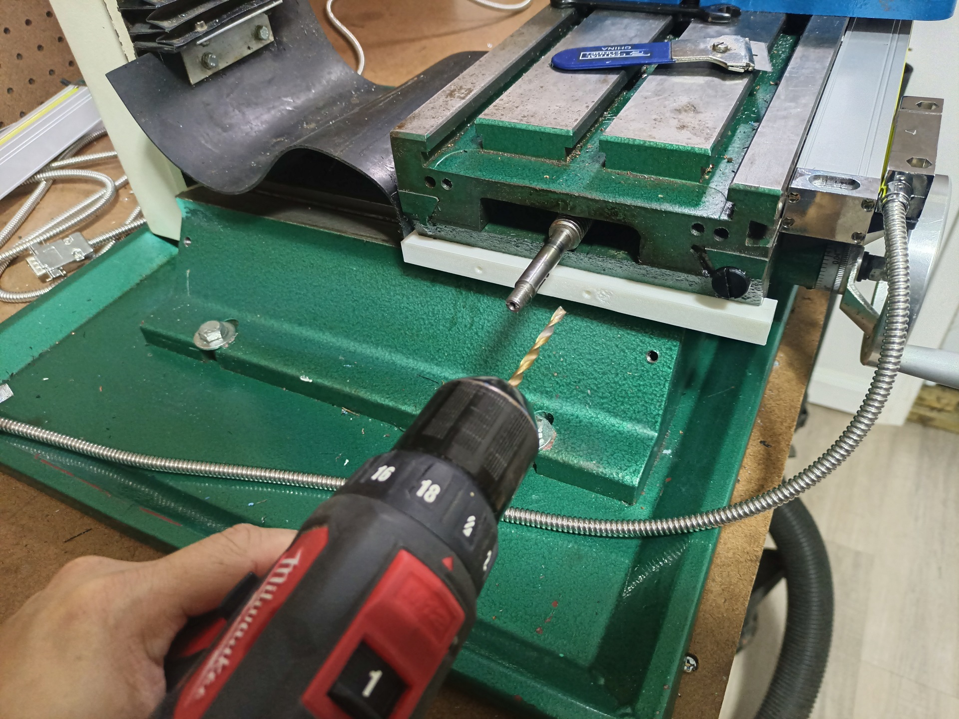
Next up, I used a jig to drill a similar set of spaced mounting holes into the saddle to accommodate the Y-axis slide.
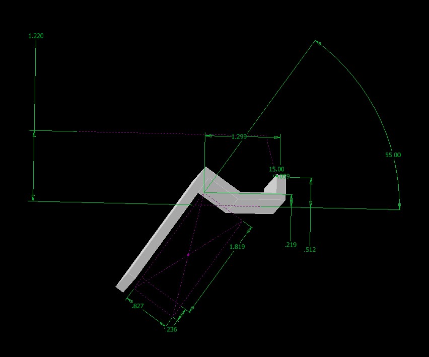
Now this thing was a lot more awkward to measure. The dimensions shown in the sketch are essentially the dimensions I took IRL with calipers, gauge/setup blocks, and so on. The bracket had to reach a little up and over the scale body, then drop down to hang the slide. I 3D printed this exact model to do visual checks, and ended up blasting out 2 revisions in PLA. This sounds like it might have taken forever, but with modern high-speeders like my Creality K2+, each Rev was really just like 20 minutes.
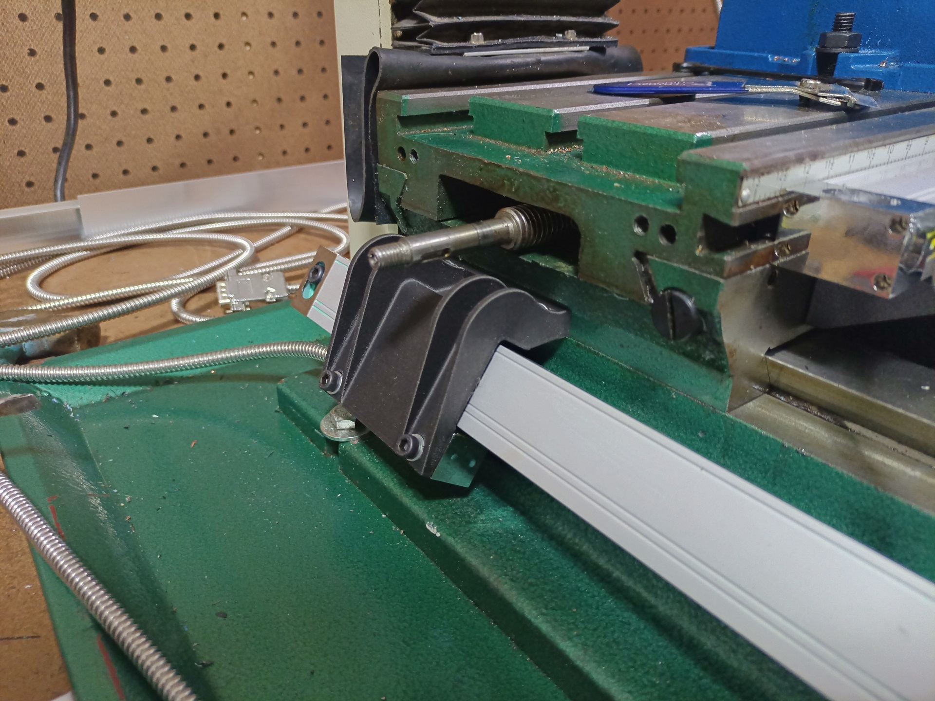
When I liked the fit, things got more serious and… a little weirder looking. This final revision was also made in carbon fiber filled nylon. It’s secured to the saddle with two screws wearing fat washers, and features four curving ribs to give it rigidity as it does the ol’ reacharound.
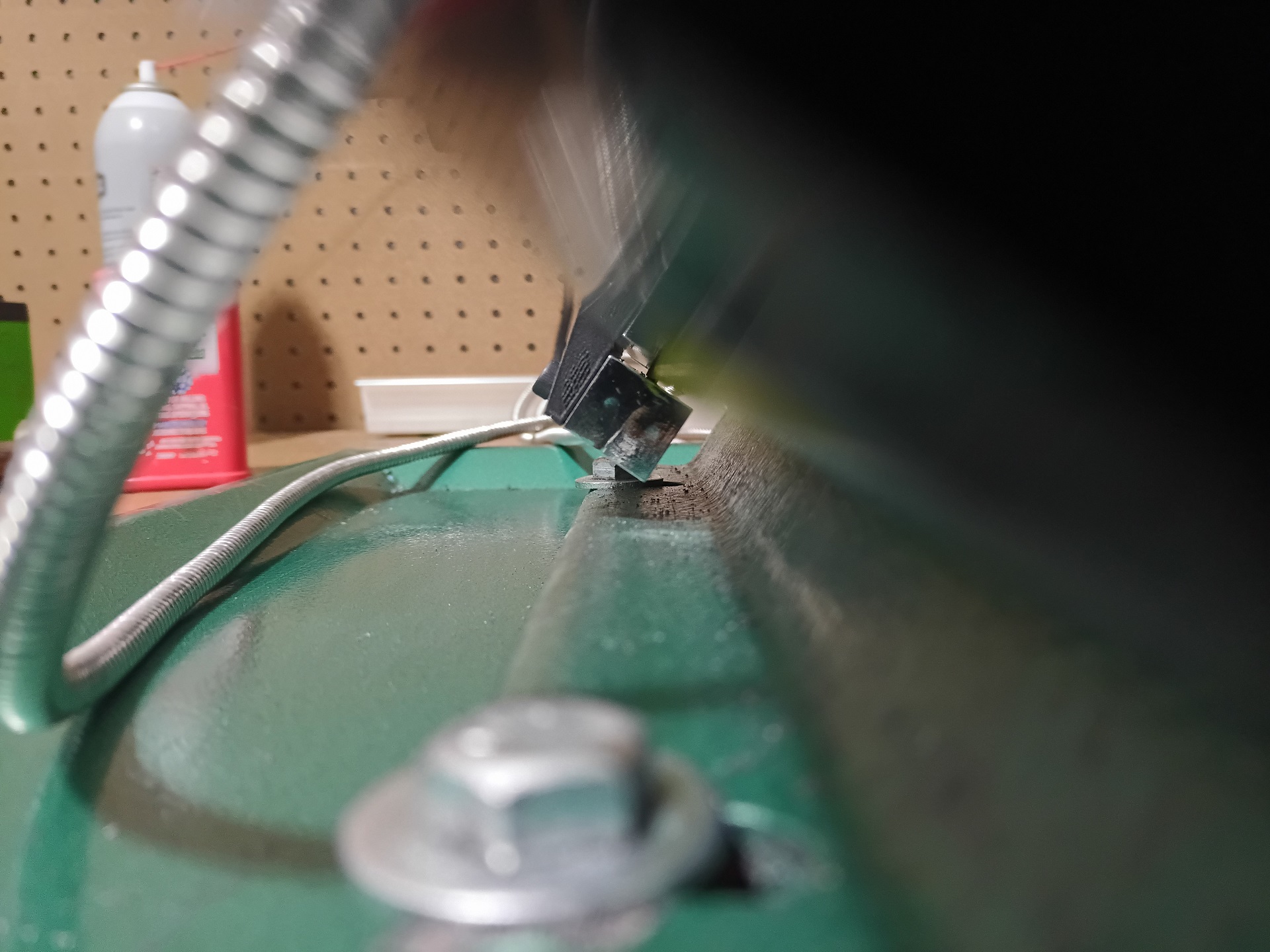
Very happy with how this turned out, as the slide barely clears everything yet remains fully aligned through its whole travel.
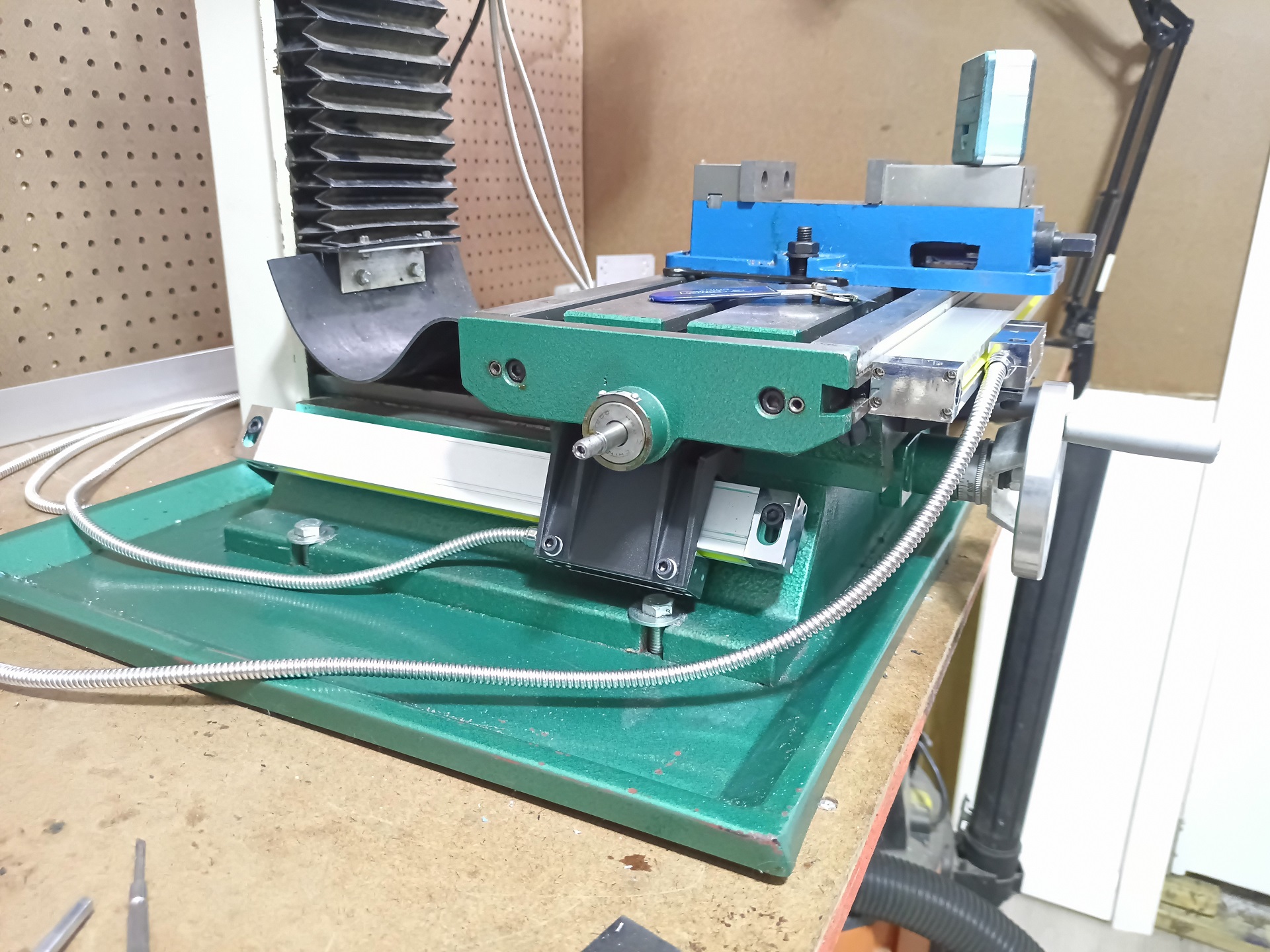
Not only that, but it was designed to accommodate the X-axis leadscrew and table endcaps. This is the farthest the table will crank that-a-away, and the leadscrew bearing bumps are just a few millimeters away from the Bracketry!
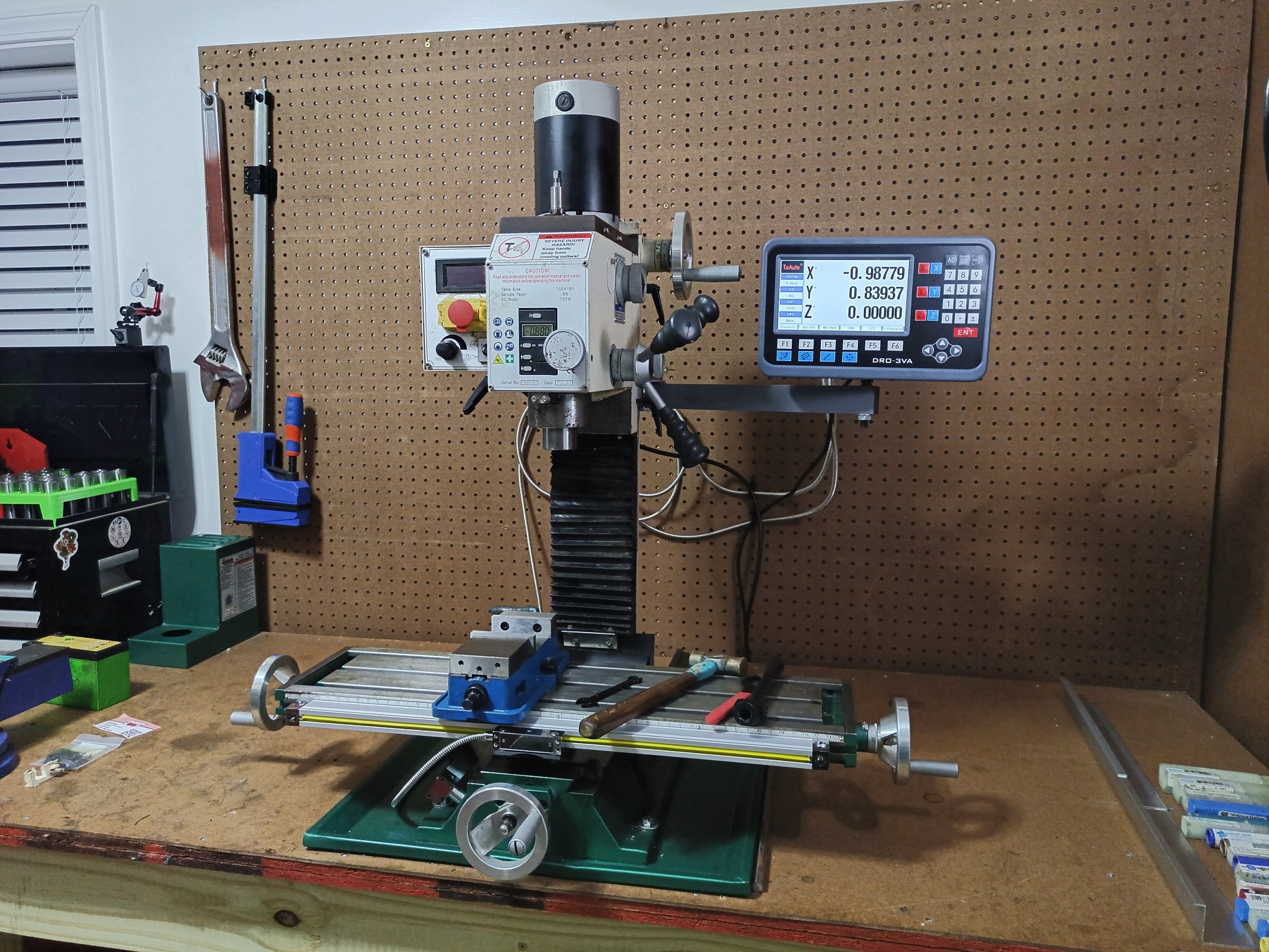
And there we have it. Suddenly this thing became 10 times as useful (or me 10 times as lazy). But at least it means I can bust out robot particulates even quicker!