Chibi-Everything, part I: Kart

A double-update from the term of smaller and cute projects! First, I’ve discovered to little surprise that Chibikart will have no torque whatsoever. And second, I’ve finally gotten over my fear of XBees to mine Chibicopter back out from the pit of paused project despair in order to… attach an FTDI header to it. Oh, the backpedaling.

First, why Chibikart will be a super laid-back performer.

Last time, in testing the mostly-36-turn motor, I found out that my back-EMF (/torque) constant was a dismal 0.126 Nm/A. This was off from the predicted 0.19 Nm/A and even down from the single-winding guessed 0.16 Nm/A. There were probably two major factors involved. First, I could not stuff 36 turns onto all of the windings at all. Not even close. Besides A-phase, the rest of the phases more realistically have about 30 turns per tooth. Just this small (16%) reduction isn’t enough to explain the drop from 0.19 to 0.126, though. I’m also suspecting that the 3 little toothlets on each tooth increase my apparent air gap (since only parts of them are at the design airgap) and the rest are about 0.75mm inwards – the airgap in that area is about 1.25mm.

The depressions and raised tooth areas each occupy about half the area of the tooth, so the average airgap would be 0.875mm for one tooth.  The maximum theoretical flux density at this average surface is therefore (1.2 tesla for N42 grade magnets) * (2mm thickness / (2mm thickness + 0.875mm airgap)) = 0.83T. If the airgap were evenly 0.5mm throughout (which is the design gap), then the average flux density rises to 0.96T. The 13.5% loss of the field strength from 0.96 to 0.83 coupled with the 16% loss of winding turns means that (0.19 Nm/A) * (0.865) * (0.83) = approximately 0.136.

Plus or minus some second-order effects and nonidealities, and I think the lesson is clear – real life sucks. That, and I need to find a better stator.

The second motor was even worse.

Through more test winding, I found that 27 turns was what I could reliably wind on one tooth. Meaning very little “cancerous bunching” as seen in the first motor winding picture, and which could be completed reasonably fast without being messy. It turns (!) out that keeping the wire under high tension the whole time improved packing alot – go figure – and I added another zip tie to my winding jig as a result.

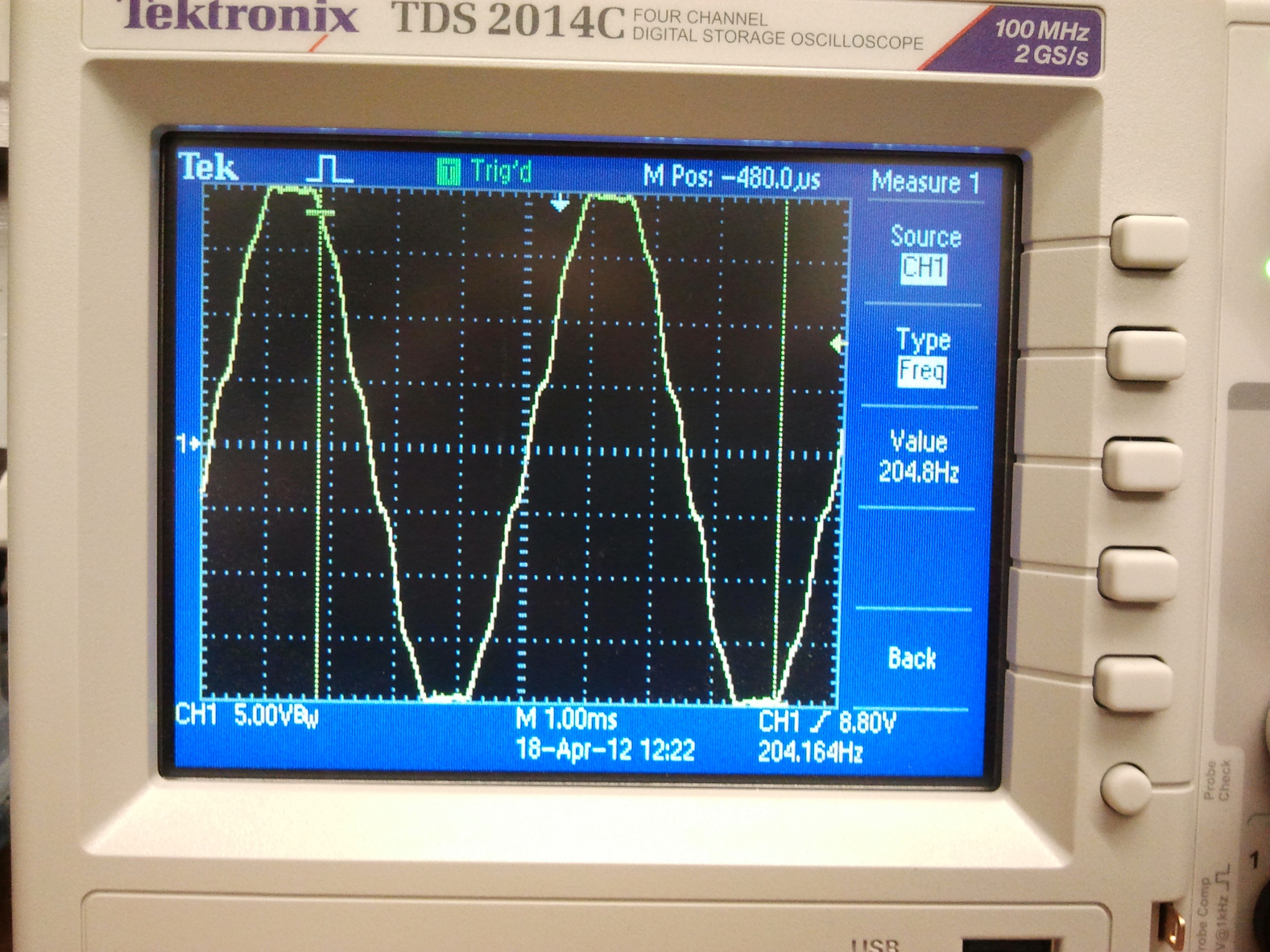
Unfortunately, 27 turns is even worse than 30 turns. The above scope capture is the lathe-o-mometer signature of the second Chibikart motor. The calculated BEMF constant is an even more depressing 0.11 Nm/A. While consistent with an incremental (27/30) decrease in the turn count, it’s still…. so soul-crushing.

By this time, I was seriously questioning if the first generation skate motors which these things are based off of ever reached their design 0.26 Nm/A. It seemed impossible given my above results. The skatemotors were true 36 turn (but single 24 gauge winding), so based on the results I got with the first motor, I should see a realistic Kt of 0.15 Nm/A.

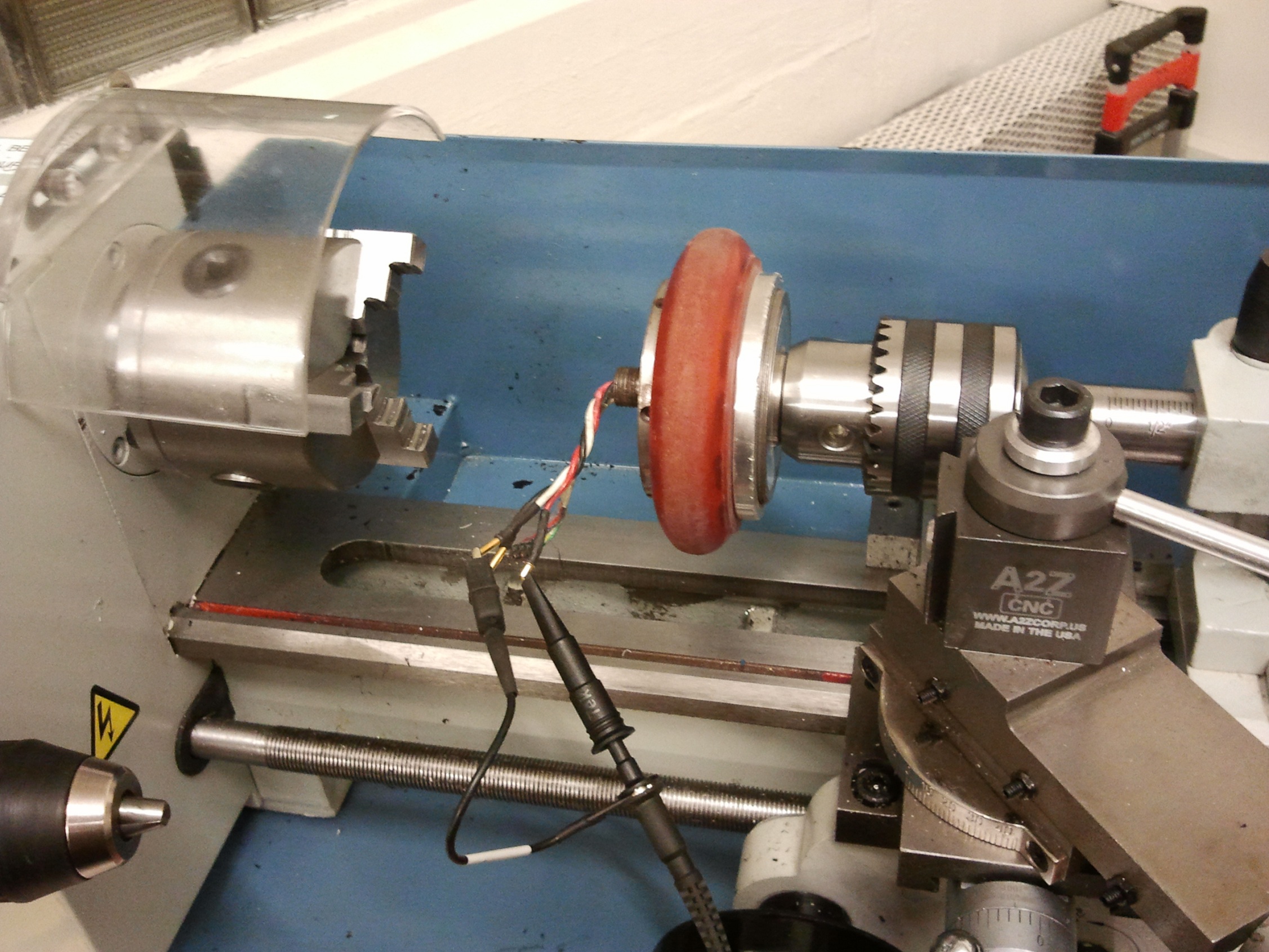
How did I find out? Well, I had to temporarily put the left RazErBlade on blocks to find out – I removed the motor and shoved it on Tinylathe. Another problem was that in this design, the wires ran out through the center of the motor, meaning Tinylathe couldn’t grab onto it at all.

Fortunately, a DeWalt 18v drill in high gear saved the day.

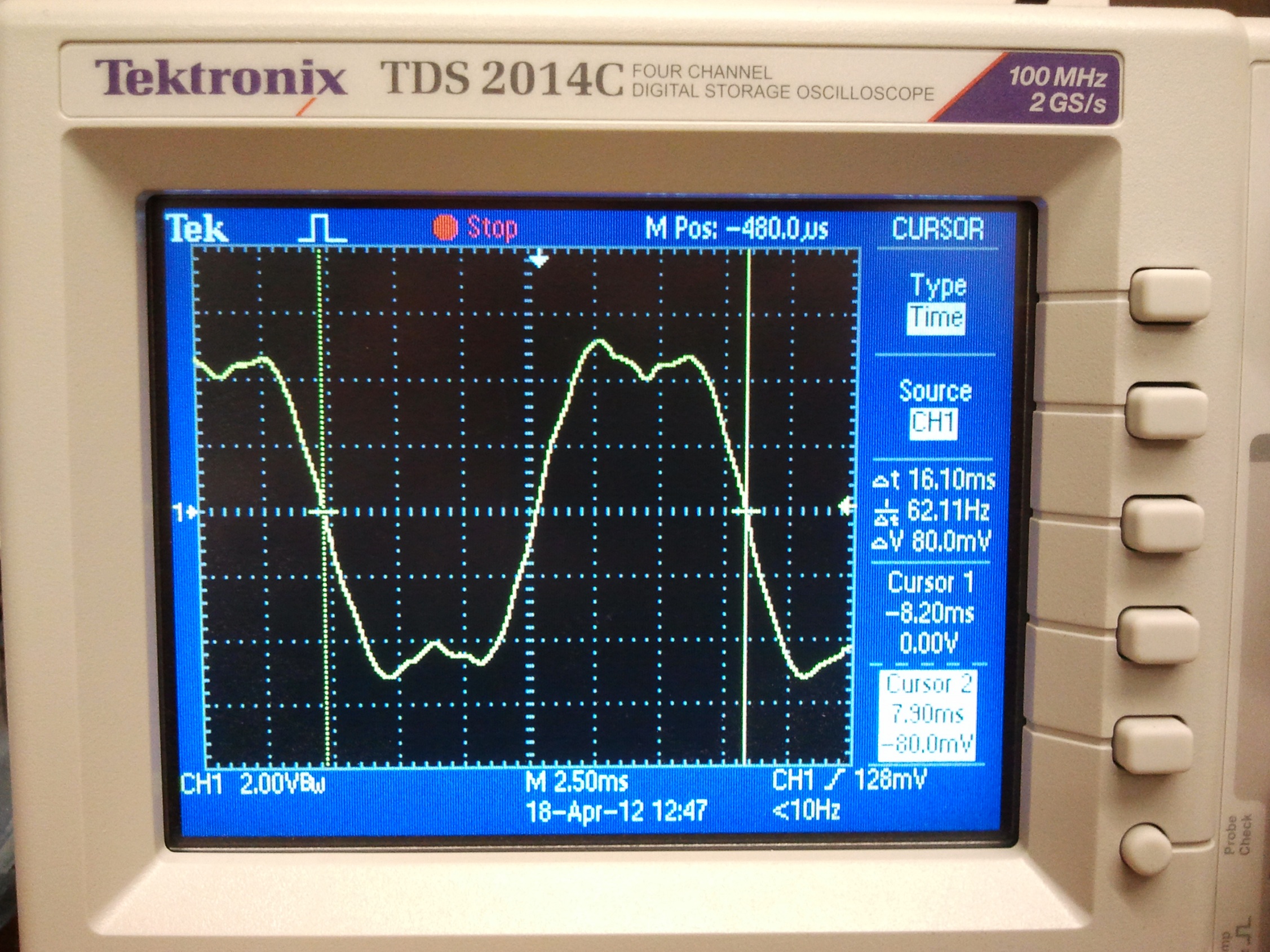
This motor’s waveform is a bit more erratic, but the average voltage magnitude is about 4.5 volts at 62 Hz. This gives a Kt of…. 0.08 Nm/A? Did I wire up this motor backwards?!

Something wasn’t right. I decided to declare this test bogus and just try running the motors using an ESC. I used Melon-scooter propped up on a table as a test jig – it has a 500w type Jasontroller right now, which is very representative of what the final control solution will be, so what better basis for comparison? A laser tachometer was used to record the no-load speed of the motors, and I used a 15 amp power supply set to 33 volts with maxed out current – the no load test shouldn’t result in such high currents anyway.

These results were telling.

  • Chibikart motor 1, ~30 turns, achieved a no-load speed of 2671 (Oh the irony) RPM on 33.0v for a RPM/V (classical “Kv” rating) of 81, and a calculated Kt of 0.118.
  • Chibikart motor 2, ~27 turns, achieved a no-load speed of 3036 RPM for a RPM/V of 92; Kt of 0.103. This is almost exactly the ratio of 30/27. Universe still makes sense: “Kv” is essentially the inverse of Kt, so a higher RPM/V is less Nm/A.
  • Skatemotor, ~36 turns, hit 2078 RPM for a RPM/V of 63 and Kt of 0.151. Well hey.

The ratio of turns alone, 36/30, does not account entirely for the discrepancy – it alone would calculate a Kv of 68 RPM/V using Chibikart motor 1 as a basis. While the difference of 5 RPM/V is certainly within the realm of “bah, close enough”, I think the shape of the tooth and arms is a major higher-order effect that linear models like “T = k*NBLR” doesn’t capture. The original skatemotor stators did not have those stupid toothy things.

Now, why is Kt (calculated) different from Kt (measured-with-oscilloscope-and-lathe)? I should probably mention that Kt changes with the type of drive input (sinusoidal, 120 degree trapezoidal which is the standard, 180 degree trapezoid…) and the phase of the drive input (advanced, retarded, etc.). This is something I kind of sweep under the carpet when explaining How Moter to someone because it’s very mathematical in nature, so for your amusement, here is how moter for real and how2controlmoter.

If I can hold 27 turns on each motor from here on out and maintain 0.11 Nm/A, then Chibikart will have a maximum launch force at 20 amps of 4 * (20 A * 0.11 Nm/A) / 0.05m wheel radius, or 176N at-ground linear force. I chose 20 amps as a reasonably burst rating because not only is it roughly what a stock 350W-type Jasontroller outputs without modification, but to heat up a roughly 80 gram (estimate of the total winding weight*) copper chunk from 20C to 200C, the maximum temperature rating of the magnet wire I used, at 20 amps will take about 30 seconds. The actual math: (0.384 Joules/(gram-Kelvin) for copper [1] * 180K thermal differential * 80 grams) / (20 amps ^2 * 0.37 ohms resistance of the 27-turn motor line-to-line) yields about 37s.

Why 30 seconds? Because I have to put a definition down somewhere. This is why “burst vs. continuous” ratings are bullshit if no time period of overload is given. I could reasonably pump 40 or even 50 amps into these motors for a quick launch, but they’d heat up reeeeeeeeeeeal fast if I tried to push that current continously. 30s is a generous estimate, since my magnets would be long-gone at 200C… even 80C will be enough. (However, the magnets are not in direct thermal contact with the copper, so I can certainly flame out the windings with overcurrent before any other damage is suffered)

So the bottom line is don’t expect Chibikart to behave like tinykart. With ~180N of maximum launch force, I’ll get a maximum acceleration of about 2 m/s^2. Which I guess isn’t that bad, but yeah. It will also not be happy at all going up the de-facto vehicle proving ground.

There’s so much random math in this post that it must be of some use to someone, so I’ll lob this under “Reference Posts” too.

* Each turn on a tooth is assumed to have an average dimension of 21mm length and 10mm width, for a total perimeter of 62mm per turn. There are 27 turns of 6 strands of parallel wire, so on each tooth is 10.04 meters of wire. There are 12 teeth, so the total length of wire in a motor is about 121 meters. In feet, that is 395 feet. #28 gauge magnet wire is 2028 ft/lb so the total mass of copper in each motor is .19 lb – or 3.11 ounces, or about 87 grams.

Hub Motors on Everything: More Chibikart Motor and Frame!

hi here is a chibbi kart

….okay, so only sort of, but it’s RIGHT THERE!

I have a newfound respect for 80/20. I’m not sure why I’ve never used it before – possibly because I thought it was immensely expensive (the material isn’t too bad – 1 x 1 is on average $20 for 6 feet [1]) and heavy (which is kind of true). That whole frame came together in around 2 hours net work time, which really means like 4 hours with the amount of MITERS ADD I tend to have. Whats’s expensive about the system isn’t the extrusion, but the accessories – slot nuts, for instance, tend to be $8-10 for 50, and little specialty things like hinges or plate fasteners are way overpriced for what they are. I guess it’s like selling printer cartridges and glossy photo paper to make up for the money that selling printers doesn’t earn. Fortunately I’m in a position to generate my own random interface hardware, like the corner joists.

While a fully t-nutted plate frame of the type I typically make would have gone together faster, it would have been far more expensive (necessitating me buying 4 foot or 3 foot plates of aluminum) and not nearly as adjustable.

Here’s a closeup of the underside of the seat. I discovered that the seat mounting bracket was more like 6″ across than the 5 7/8″ specified, but all that entailed was untightening the two mounting rails and moving them 1/16″ further apart. The seat mounts are 3/8″-24 cap screws – overkill under any circumstance except, you know, the seat coming with those.

And the pedals are now mounted too. It’s beginning to look like something!!!!!!

The adjustability of 80/20 slot nuts were very clearly illustrated when I found the CAD model’s seating and foot rest arrangement was “ergonomically incorrect”. The seat is further forward than its surplus website image led me to believe. Solution? Slide the seat back 2 inches and the foot rest forward an inch or so!

The steering wheel, while still for show, is probably going to be final since I still haven’t moved on buying anything to replace it…

A closeup of the placement changes – reference this drawing. In total, things have moved maybe 3 inches further apart. While Chibikart is clearly not for anyone who is not short and Asian, I will say that this still made a ton of difference in terms of comfort.

back to hub motor work

Last time, I test wound one of the stator teeth for Chibikart’s hot-modded Skatemotors. With that in mind, I now needed to mate the copier motor stators to the center shafts.

While in the 100mm skatemotors’ original designs I had called for a plastic (3d printed, injection molded, what-have-you) hub with an integrated “key” to rotationally constrain the stator, I opted for a little bit of machining time and made some aluminum sleeves with key slots cut through them. Nothing goes into the key slot, but the idea is that the OD of the sleeve is very slightly larger than the stator bore such that pressing it into the stator causes the open slot to compress a little, also gripping the inner shaft in the process.

This worked great for 3 shafts. The fourth was…. a little special, but nothing some Loctite 609 couldn’t fix. With the operation complete, I now have four hub motors ready to wind….

….

…crap, I actually have to wind it now?

Also seen above is my choice of retaining for both the stator hub and the can bearings. Those are “low profile retaining rings” for 15mm shafting. On each shaft is an inner and outer set of grooves – the inner set is for holding the stator, the outer set for spacing the bearings exactly apart. This system is one that I enjoy so far – the design change from “weird double sided machined stepped shaft” is welcome, and makes the shaft much easier to manufacture. In fact, it’s designed to be the cross section of stock 15mm metric keyed shafting if I need to poop out a few more; the dominant philosophy being if I can make it on a manual machine in 10 minutes, it will take a CNC lathe like 30 seconds.

The center threaded bore was also drilled out for a 1/4″-20 clearance hole, since I will be bolting the shafts to my axle anchor blocks and running them under plenty of preload.

winding and characterizing the motor

I have to do this eventually, so here goes….

…wait! First, I was curious about these copier stators. They have 3 little ‘toothlets’ on each main tooth, presumably so the motor can act as a stepper motor with finer resolution than flat-topped teeth. There were two downsides to this design which makes it a little suboptimal for hub motor use – the raised ‘toothlets’ vs. the valleys between them meant that the effective average airgap between stator and magnet was larger, resulting in less poorer flux coupling (less torque), and the arms themselves were kind of wimpy and thin in cross sectional area compared to the ends of the teeth, meaning they could saturate when the permanent magnetic field and the stator field aligned (i.e. less torque).

So I used FEMM analysis software made a test winding that was representative of one phase – 36 turns per tooth, four teeth wound.

This technically doesn’t have to carry any current, so easy one strand windings were used. The magnet wire was just run straight out through the slot.

Next came the fun part:

MACHINING THE MOTOR WHILE RUNNING! Like the age-old East Asian practice of consuming living seafood, machining the motor while it runs is a….

… just kidding, this is Lathe-o-mometer. While I have done drill-o-mometer and ever air-die-grinder-with-an-R/C-car-wheel-o-mometer with previous wheelmotor iterations before, the BRAND NEW MINI-LATHE IN THE IDC MINISHOP!!! is a speed-controlled and stable fixture.

The *-o-mometer procedure is to view the back-EMF waveform of the motor on an oscilloscope while it is being spun by an external speed source. The exact shape of the BEMF, and hence the motor’s potential future torque-producing-hub-like behavior, can be deduced from the peak-to-peak voltage and the measured AC frequency. That is,

I set the scope to average a whole bunch of readings (namely 16)  once the lathe spindle spun up to ‘cruising speed’, so the result is a clear snapshot of the BEMF of one phase. And….. what the hell? Why is it triangular? These things are supposed to be trapezoidal. I know a triangle is like a trapezoid with no flat top, but this is ridiculous. Anyways, the “stairstep” ripple in the waveform is the little toothlets of the stator making themselves visible.

One phase doesn’t tell me very much, besides my motor is not totally bullshit. In a typical BLDC motor, two phases are driven at any one time. So to really get the whole picture, I’d need at least 2 of the phases wound. So I did!

At first, though, I managed to wire up phase B backwards – hence creating a motor which mostly canceled itself. Oops.

That’s more like it. The measured line-to-line voltage is approximately 60 volts, which really means a differential voltage of 30 volts across the two phase leads. This problem has confounded me for a long time, but I only understood why it happens very recently – the scope treats a single-ended measurement as a deviation from zero volts, and its own ground is defined always as zero volts. So even though -30v to 0v and +30v to 0v are both 30 volts differential, the swing of -30v to 30v is “60 volts”. If I had used 2 channels and a true differential measurement (ch1 – ch2) with a common ground, then the waveform would actually be 30 volts peak to peak.

The other important number is “203.3 Hz”, which is the electrical frequency of the motor.

To convert 30 Vpp and 203.3Hz into a useful motor torque constant value in V/(rad/s), I multiply 203.3Hz by 2*pi to obtain a value in electrical rad/s, then divide by 7 to obtain a value in mechanical rad/s (because in a 12 tooth / 14 magnet motor the electrical speed is 7 times the mechanical speed). Then 30v is divided by mechanical rad/s to yield V/(rad/s), and the magical number is…  0.164 V/(rad/s) or Nm/A.

This was pretty promising – 0.164 might have been quite a ways off from the original estimate of 0.23-0.25, but at least it 1. wasn’t outright terrible and 2. showed to me that the stator teeth were not saturating all over the place.

With the motor characteristics verified, it was time to beast the windings:


oh god it looks cancerous

Okay, I give up. Hobbyking, how the hell do you guys do this?

While I thought previously that 36 turns was a reasonable count, that test was done on one tooth, very neatly and patiently arranged, and compacted at the end. It turns out that this is not always possible to do with adjacent teeth, and once the turns pile up even a little bit, the destruction of order is very rapid. This stator shows clear signs of “hobbykinging” in the second sense – the windings almost falling out of the slots because they have been piled so messily during the process.

Really, I was able to stuff only 36 or so turns onto 2 teeth on phase A. Everything else is probably 33 turns or so – I some times could not fit the last few at all. I might have to either rethink the hex-28 gauge winding scheme or reduce the turn count officially (sacrificing Kt even more), or just have more patience while winding. We know the latter isn’t going to happen, so I’ll have to go back to playing with other wire sizes. What’s distressing is that the stator is pretty much totally filled out – I’m not sure what single-strand big wire size will get me the same level of turns.

Nevertheless, I pressed forth with terminating this stator. There’s absolutely no hope of ever installing Hall sensors in these windings, so I’m going to pray to Motor Jesus that Jasontroller can start these under load.

I once again took a page from the ICBM (Inexpensive Chinese Brushless Motor) Design Book and just heat-shrunk a section of my magnet wire pigtails to use as main motor leads. Soldering real wire inside the motor takes up previous space that I’m not certain exists in this design. The “star point” was made by running a small length of jumper wire (the red wire) between the endpoints of the phases.

And once I packed it back up inside the skate wheel, here it is back on Lathe-o-mometer and…. wait, did it get worse? Now it pumps 30 volts but at 277 Hz. That’s a performance decrement of over 36%. This is probably caused by my inability to shove the proper number of turns onto the stator in real life.

This new measurement results in a Kt of a little over 0.126. Sadness :(

The resistance of the motor from line to line came out to be about 450 milliohms – I predicted about 400, so this is good to see. However, this could still be too much – say I am running at 20 amps – I’m still losing ((20 amps)^2 * 0.45 ohms) watts to heating! The motor is not going to last long at all being a 200W heater.

But at least it sounds and looks great!

I’m probably going to pull out the Excel spreadsheet or MATLAB script and run some possible combinations of turns vs. wire gauge vs. paralleled strands to see if I can get a reasonable combination of torque production and low core resistance. However, physics constrains me significantly – as packed as the slots are, my losses on average are going to remain the same no matter what. The only thing that will result in more crank is packing more copper into the slots.

The 100mm skate wheel motors have always been underpowered for vehicle moving, but here’s hoping they work out!