A double-update from the term of smaller and cute projects! First, I’ve discovered to little surprise that Chibikart will have no torque whatsoever. And second, I’ve finally gotten over my fear of XBees to mine Chibicopter back out from the pit of paused project despair in order to… attach an FTDI header to it. Oh, the backpedaling.
First, why Chibikart will be a super laid-back performer.
Last time, in testing the mostly-36-turn motor, I found out that my back-EMF (/torque) constant was a dismal 0.126 Nm/A. This was off from the predicted 0.19 Nm/A and even down from the single-winding guessed 0.16 Nm/A. There were probably two major factors involved. First, I could not stuff 36 turns onto all of the windings at all. Not even close. Besides A-phase, the rest of the phases more realistically have about 30 turns per tooth. Just this small (16%) reduction isn’t enough to explain the drop from 0.19 to 0.126, though. I’m also suspecting that the 3 little toothlets on each tooth increase my apparent air gap (since only parts of them are at the design airgap) and the rest are about 0.75mm inwards – the airgap in that area is about 1.25mm.
The depressions and raised tooth areas each occupy about half the area of the tooth, so the average airgap would be 0.875mm for one tooth. The maximum theoretical flux density at this average surface is therefore (1.2 tesla for N42 grade magnets) * (2mm thickness / (2mm thickness + 0.875mm airgap)) = 0.83T. If the airgap were evenly 0.5mm throughout (which is the design gap), then the average flux density rises to 0.96T. The 13.5% loss of the field strength from 0.96 to 0.83 coupled with the 16% loss of winding turns means that (0.19 Nm/A) * (0.865) * (0.83) = approximately 0.136.
Plus or minus some second-order effects and nonidealities, and I think the lesson is clear – real life sucks. That, and I need to find a better stator.
The second motor was even worse.
Through more test winding, I found that 27 turns was what I could reliably wind on one tooth. Meaning very little “cancerous bunching” as seen in the first motor winding picture, and which could be completed reasonably fast without being messy. It turns (!) out that keeping the wire under high tension the whole time improved packing alot – go figure – and I added another zip tie to my winding jig as a result.
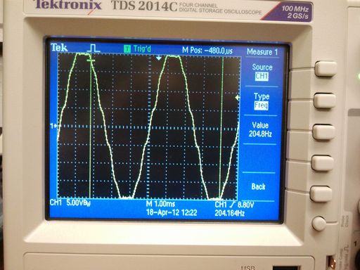
Unfortunately, 27 turns is even worse than 30 turns. The above scope capture is the lathe-o-mometer signature of the second Chibikart motor. The calculated BEMF constant is an even more depressing 0.11 Nm/A. While consistent with an incremental (27/30) decrease in the turn count, it’s still…. so soul-crushing.
By this time, I was seriously questioning if the first generation skate motors which these things are based off of ever reached their design 0.26 Nm/A. It seemed impossible given my above results. The skatemotors were true 36 turn (but single 24 gauge winding), so based on the results I got with the first motor, I should see a realistic Kt of 0.15 Nm/A.
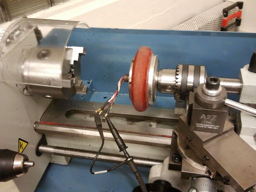
How did I find out? Well, I had to temporarily put the left RazErBlade on blocks to find out – I removed the motor and shoved it on Tinylathe. Another problem was that in this design, the wires ran out through the center of the motor, meaning Tinylathe couldn’t grab onto it at all.
Fortunately, a DeWalt 18v drill in high gear saved the day.
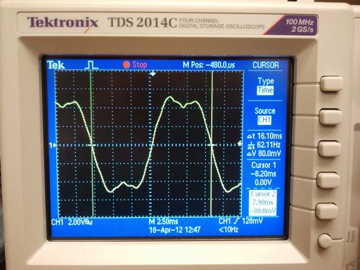
This motor’s waveform is a bit more erratic, but the average voltage magnitude is about 4.5 volts at 62 Hz. This gives a Kt of…. 0.08 Nm/A? Did I wire up this motor backwards?!
Something wasn’t right. I decided to declare this test bogus and just try running the motors using an ESC. I used Melon-scooter propped up on a table as a test jig – it has a 500w type Jasontroller right now, which is very representative of what the final control solution will be, so what better basis for comparison? A laser tachometer was used to record the no-load speed of the motors, and I used a 15 amp power supply set to 33 volts with maxed out current – the no load test shouldn’t result in such high currents anyway.
These results were telling.
- Chibikart motor 1, ~30 turns, achieved a no-load speed of 2671 (Oh the irony) RPM on 33.0v for a RPM/V (classical “Kv” rating) of 81, and a calculated Kt of 0.118.
- Chibikart motor 2, ~27 turns, achieved a no-load speed of 3036 RPM for a RPM/V of 92; Kt of 0.103. This is almost exactly the ratio of 30/27. Universe still makes sense: “Kv” is essentially the inverse of Kt, so a higher RPM/V is less Nm/A.
- Skatemotor, ~36 turns, hit 2078 RPM for a RPM/V of 63 and Kt of 0.151. Well hey.
The ratio of turns alone, 36/30, does not account entirely for the discrepancy – it alone would calculate a Kv of 68 RPM/V using Chibikart motor 1 as a basis. While the difference of 5 RPM/V is certainly within the realm of “bah, close enough”, I think the shape of the tooth and arms is a major higher-order effect that linear models like “T = k*NBLR” doesn’t capture. The original skatemotor stators did not have those stupid toothy things.
Now, why is Kt (calculated) different from Kt (measured-with-oscilloscope-and-lathe)? I should probably mention that Kt changes with the type of drive input (sinusoidal, 120 degree trapezoidal which is the standard, 180 degree trapezoid…) and the phase of the drive input (advanced, retarded, etc.). This is something I kind of sweep under the carpet when explaining How Moter to someone because it’s very mathematical in nature, so for your amusement, here is how moter for real and how2controlmoter.
If I can hold 27 turns on each motor from here on out and maintain 0.11 Nm/A, then Chibikart will have a maximum launch force at 20 amps of 4 * (20 A * 0.11 Nm/A) / 0.05m wheel radius, or 176N at-ground linear force. I chose 20 amps as a reasonably burst rating because not only is it roughly what a stock 350W-type Jasontroller outputs without modification, but to heat up a roughly 80 gram (estimate of the total winding weight*) copper chunk from 20C to 200C, the maximum temperature rating of the magnet wire I used, at 20 amps will take about 30 seconds. The actual math: (0.384 Joules/(gram-Kelvin) for copper [1] * 180K thermal differential * 80 grams) / (20 amps ^2 * 0.37 ohms resistance of the 27-turn motor line-to-line) yields about 37s.
Why 30 seconds? Because I have to put a definition down somewhere. This is why “burst vs. continuous” ratings are bullshit if no time period of overload is given. I could reasonably pump 40 or even 50 amps into these motors for a quick launch, but they’d heat up reeeeeeeeeeeal fast if I tried to push that current continously. 30s is a generous estimate, since my magnets would be long-gone at 200C… even 80C will be enough. (However, the magnets are not in direct thermal contact with the copper, so I can certainly flame out the windings with overcurrent before any other damage is suffered)
So the bottom line is don’t expect Chibikart to behave like tinykart. With ~180N of maximum launch force, I’ll get a maximum acceleration of about 2 m/s^2. Which I guess isn’t that bad, but yeah. It will also not be happy at all going up the de-facto vehicle proving ground.
There’s so much random math in this post that it must be of some use to someone, so I’ll lob this under “Reference Posts” too.


well since you have more horizontal space to work with here, why not go doublewide on thestators and run a wider (see: orange behemoth) wheels?
or hey, what about running melon stators >_>
go double wheel’d. screw the #s and just put 2 wheel on each jackshaft with 8 separate controllers. It will look BADASS.
So i have a 63-54 motor that i ran waaaaay to hot.
the windings melted and shorted.
So, i could just move on and ditch the motor, but every other part is perfect! the magnets are fine, the shaft and bearings are okay, so i wouldn’t want that.
do you think a rewind would be a good idea?
i would want to do a low turn single strand wind. Like the 80-100 motors that are wound 7 or so turns with 1.5 mm wire, if you have seen them
http://www.youtube.com/watch?v=1coulqFPlog
thanks