The Carly Rae Jepsen Wallbanger: A New 12lb Robot Premier at Robot Battles 2012

Excuse me while I try to explain why this thing exists.

Basically, I spent 3 days at the GT Invention Studio putting together a new 12lb bot after binging cordless saw motors at Harbor Freight. The bot is a “full body” spinner, classically called a “thwackbot”, which has a very quick and powerful drivetrain (made of the aforementioned cordless saw motors) to spin itself at high speeds. I have no reasonable explanation for the Carly Rae Jepsen part. It doesn’t really need to exist.

But the benefit of it existing is one more entry for me at Robot Battles 2012, as well as a chance to explore another possible way to press cordless tools into service for robotic drivetrains. I haven’t had a 12lber in a long time, and this thing is fun to drive.

Long story short, the Model 67026 18 volt cordless saw from Harbor Freight is usually on sale for $25 to $30 and contains the following:

Beefy. I actually binged 3 different types of cordless saw: a jigsaw, a reciprocating saw, and the cordless circular saw. I might make a Beyond Unboxing post about the three some time, but right now the conclusion is that the jigsaw and recip saw are too specialized to be of immediate use to a robot drivetrain.

Unlike the average shady cordless drill, these gearboxes have random Chinese off-brand 775-size motors. That’s already a pretty substantial horsepower increase.

Unscrewing the gearbox itself from the weird cast output structure, I found that the ring gear was actually well-contained and modular. A large iron-bronze bushing pressed into the ring gear cup supports the 12mm-stepping-to-10mm output shaft. The nub thing is the spindle lock for changing out blades and doesn’t transmit any torque.

The gearbox is a single stage planetary gear with teeth much larger than drill motors – looking close to 1.0 module (24 pitch-ish) with an 8mm face width, though I didn’t measure diameters. The ring gear has 42 teeth and the pinion has 10, making this a (42/10)+1 or 5.2:1 gearbox. With a 3800RPM rated output. That’s pretty damned fast, so it might not be directly useful for a drivetrain in most cases, but certainly with external reduction or just tiny wheels.

I decided to find a way to use the gearcase by itself, without the strange casting. The iron-bronze output bushing of the motor lends itself well to using a stacked plate configuration to approximate the stepped profile of the business end of the gearbox. Behold:

The first (innermost) layer supports the plastic gearcase, and the second layer holds the bushing in place. The dimensions worked out very nicely.

So what does the rest of this thing look like?

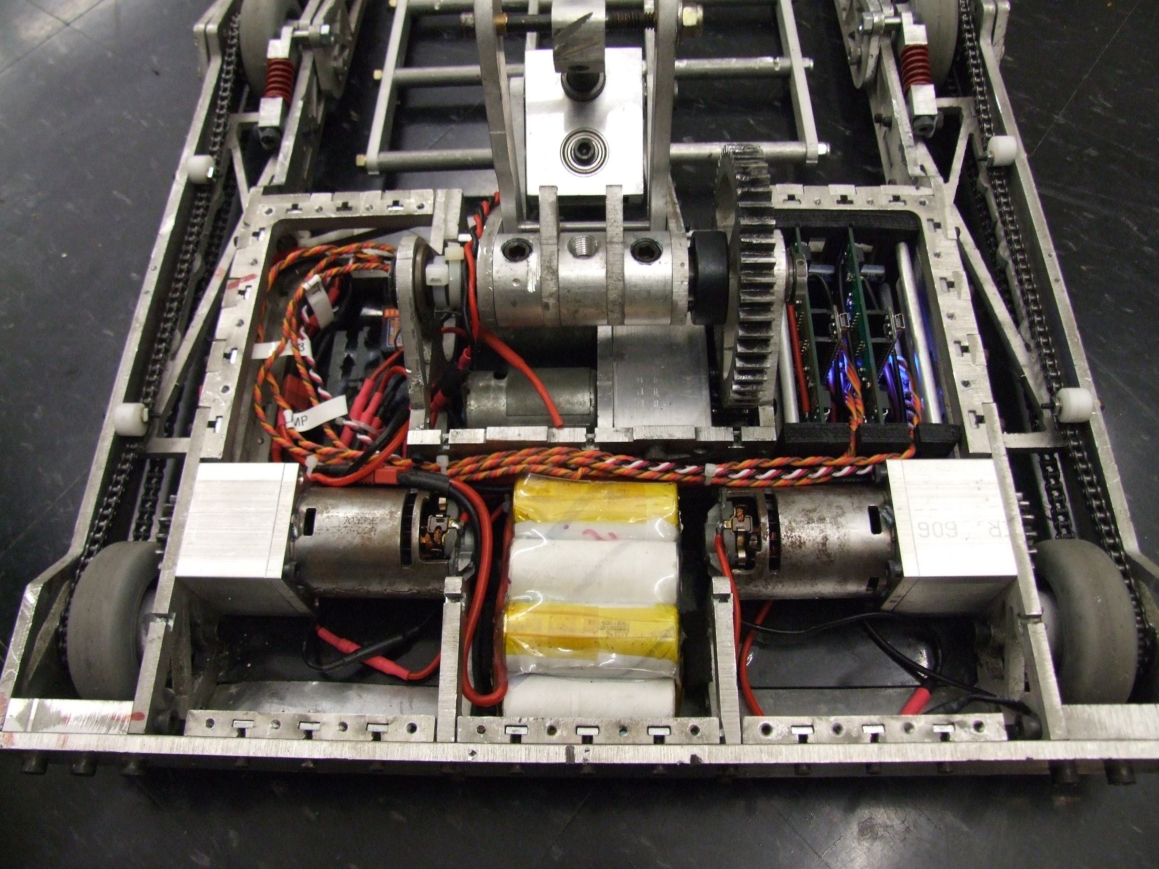
I generally have trouble explaining my design rationales, so that’s it. I basically decided it was going to be a 2-wheel-drive “thwack” type bot. A few frame drawings were made and discarded before they reached the 3d model stage. One plan was to make the bot essentially round and have steel knocking teeth on the outer radius (looking much like a “shell” type spinner), but it was deemed impractical in the limited time I had. Another design had the wheels inboard, only 3 or 4 inches apart, to maximize the inertia of the frame. I did want to retain significant mobility, so a very narrow wheel track with the motors facing inwards was ruled out. I then started the frame design constraint by spacing the motors far enough apart to install a Ragebridge board if needed, since I had packed a spare.

Finally, realizing that the easiest way to mount the motors was with thru-holes and standoffs, I elected to make the robot entirely from standoffs and plates, which can be quickly whipped out on the GTIS waterjet (yes, even when I escape MIT, I cannot escape my waterjet addiction).

Four long sticks of grade B7 threaded rod clamp the frame together. It’s an essentially one-piece frame that can’t be messed with without taking the nuts off and hence loosening everything. However, when the rods are cranked, the frame should be stiff enough to not deform under the hits it can deliver.

Exercising my Atlanta resources for the first time in years, I went to Metal Supermarket in Doraville and bought some 1/4″ steel plate and 1/8″ aluminum, then drove to McMaster-Carr (yes, to McMaster – this was something that regularly happened during high school FIRST seasons) for the rest of the parts. I also bought some wire and connectors from Hobbytown USA in Duluth, another one of my old robot trip stops

This is the series of 2 plates mentioned previously. I had to do quite a bit of “deburr-boring” to get the holes to the proper dimension – must have screwed up measuring the roughly molded plastic.

The wheel mounting arrangement is a little unconventional. The wheels are 3″ “McMasterbots” wheels, the same that I will also be using on Überclocker. The width of the wheel, plus a little here and there, is perfect for suspending off the 10mm portion of the shaft. A small spacer, machined to the correct length, will be the axial constraint method. The shaft otherwise has no snap ring grooves or shoulders to axially locate it when force is applied into the end – i.e. pushing the shaft into the ring gear. The spacer will act as a thrust bearing in this situation, and I made it appropriately out of the iron-bronze output bushing found in a typical drill motor (it can be seen on the shaft in the picture).

The end of the shaft has a convenient double-flat profile, so the wheel hub is just a single waterjetted biscuit of aluminum with a matching double-flat bore.

The holes in the wheel were drilled in-place using the hub biscuit as a template. The wheel bore itself was enlargened to 10mm first using a lathe and drill. This whole thing is retained by the original blade locking screw from the saw.

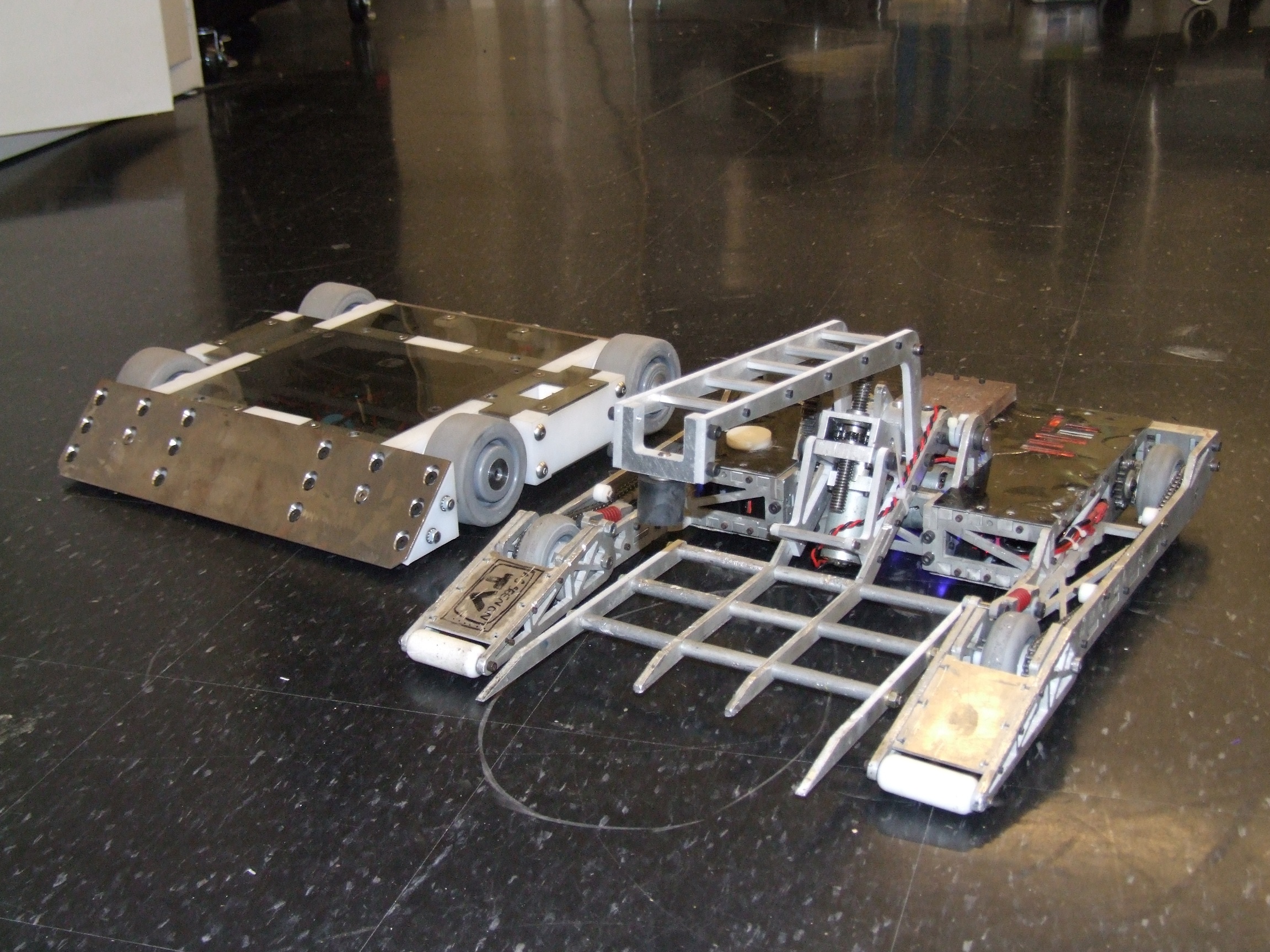
Here’s the bot laid out in pretend form, before I threaded the long rods through.

And here is the whole frame bolted together.

I like those middle rail bulkhead things alot. At first, I was intending to waterjet whole rectangles with thru-holes, but decided it was a waste of material. I split each rectangle into sides, and each side actually looks like a little open-ended wrench that slides over the threaded rod (see previous picture – they’re next to the frame standoffs). Therefore, I can install them after threading all the standoffs through, in-place. The idea was to have a fast way of dismounting electronics if I needed.

Speaking of electronics, I decided to fall back to a classic solution of mine: A123 cells. I have 2 strings of 15-cell nicads drawn in the model, and the intent was to use the stock batteries that 18v drills came with. However, the cells are very low quality in those cheap things, and I’ve measured them as dumping *10* amps, max. In a sub-C package.

Kind of derpy. Even with two strings in parallel, the voltage stability would be unacceptable with those 775 motors throwing the bot around. On the contrary, the A123s can happily shit out 60-80 amps briefly.

I made a “flexy” pack since it needed to span the bulkhead and the A123 cells were too wide to fit in the design. The pack is 6S1P, and there will be 2 in the robot for 6S2P, or 19.2v at 4.4Ah. Much more substantial than the 18v and 2.3Ah the drill packs would have offered, and these weigh less.

Instant robot.

I’m gonna have to remember to add more zip ties to the thing in order to retain the batteries radially.

These motors hit 3800rpm at their native 18 volts. This results in a linear speed of something like 35mph tops, but I will never get up to that speed on stage, clearly. The bot does handle quite well for being so fast, because it’s also extremely wide and has high traction. The maximum rate of spin with the motors going full opposite is about 800RPM, for a linear tip speed of around 40mph.

Way too fast for Robot Battles – there is a 20 feet-per-second max anything speed rule. Luckily, on 50% dual rates set by my transmitter, the spin rate is much closer to 20FPS. So this bot will just be run with my radio’s gentler stick settings.

So what’s controlling this rig? I brought along my spare 65A Botbuttz controllers in case the Ragebridges in any of the bots failed or needed emergency replacement. These are brainwashed Hobbyking brushless ESCs which have been convinced they can only drive brushed DC motors reversibly. With firmware being open-source and developed by members of the robot community, nice things not normally found in cheap single channel ESCs such as exponential response and ultra-narrow deadband are possible. So in other words, this thing is smooth. They also run perfectly on 6S A123s, and were a good amperage match for the 775 motors.

So here’s the side of the thing, with steel knockers. They’re unhardened, so I don’t expect them to stay sharp very long.

Here’s some test video!

This thing basically goes up in 7 hours. I don’t expect it to last very long, but it will probably be a (and only one) hit.
The Dramatic Story of How I Saved the Ragebridges and Suck at Reading Datasheets, and an Überclocker Update

Alright, here we go. The post where I have to fix everything, because I have to leave for Atlanta and Dragon*Con 2012 (and its associated Robot Battles) in 8 hours. After assembling 2 more Ragebridge boards, finding that all of them had Resetting Regulator Disorder, I tried several increasingly desperate hacks to get the boards reliable before discovering a small nuance in the datasheet. In all, I managed to blow up another board (due to a slight… assembly problem), but I believe I have finally found a stable operating plateau for the Ragebridge boards.

Oh, and Clocker works. Here’s a recap:

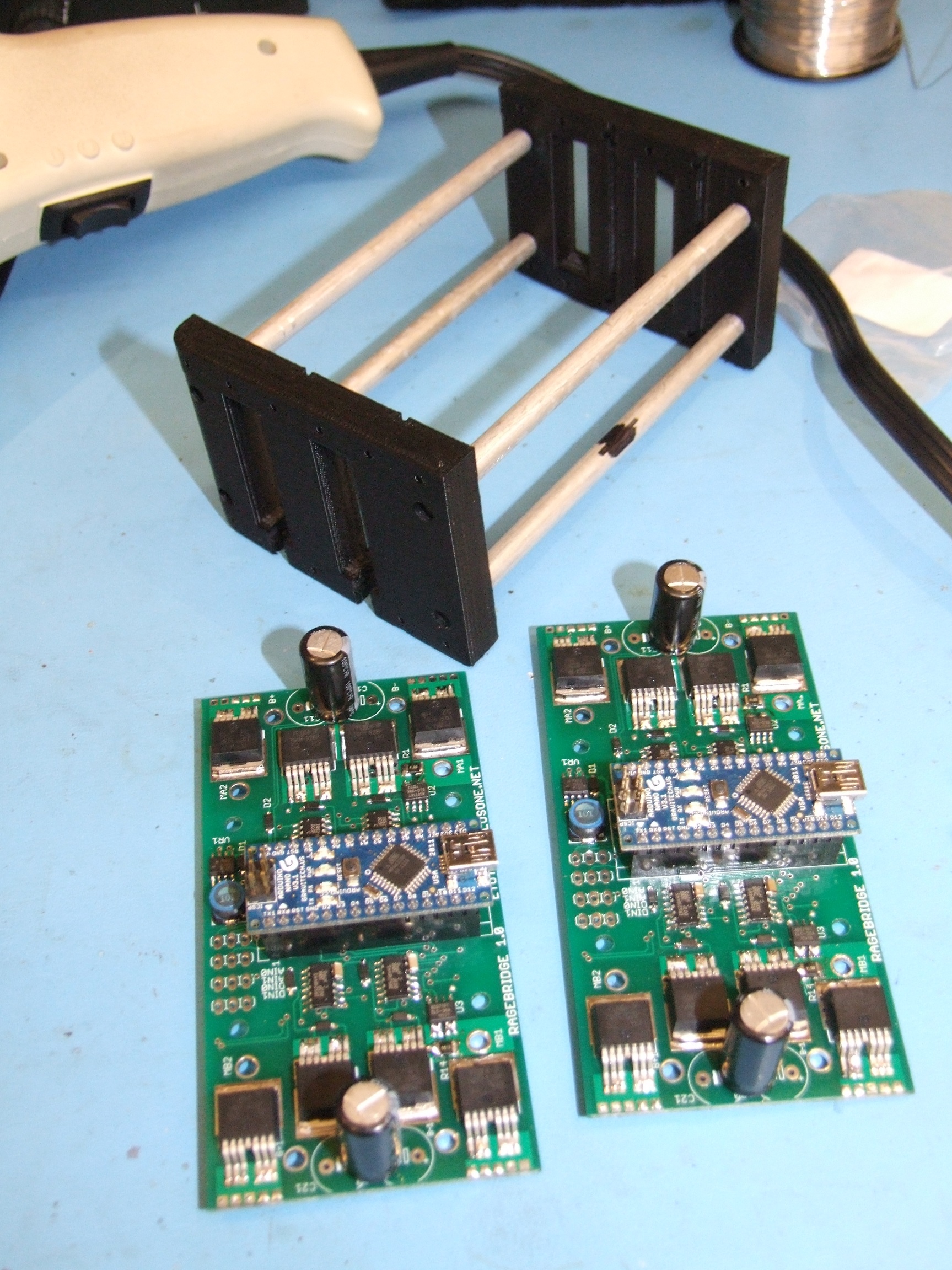
One of the first problems I had to solve before actually getting to work on the Ragebridges was how to mount them. Formerly, Clocker’s “eBays” held 2 Victor 883s each. I wanted to group the Ragebridge boards on one side of the bot to avoid having to have long runs of distribution wiring, and because mounting two mostly bare PCBs horizontally greatly increases the risk of robot grunge getting places they shouldn’t.

I couldn’t really stack two of the Ragebridge boards horizontally, though, because they were slightly too tall to accommodate the thickness overhead of mounting standoffs. If I had shorter capacitors, this could have worked fine, and I was planning on building a small enclosure around the boards with fan cooling.

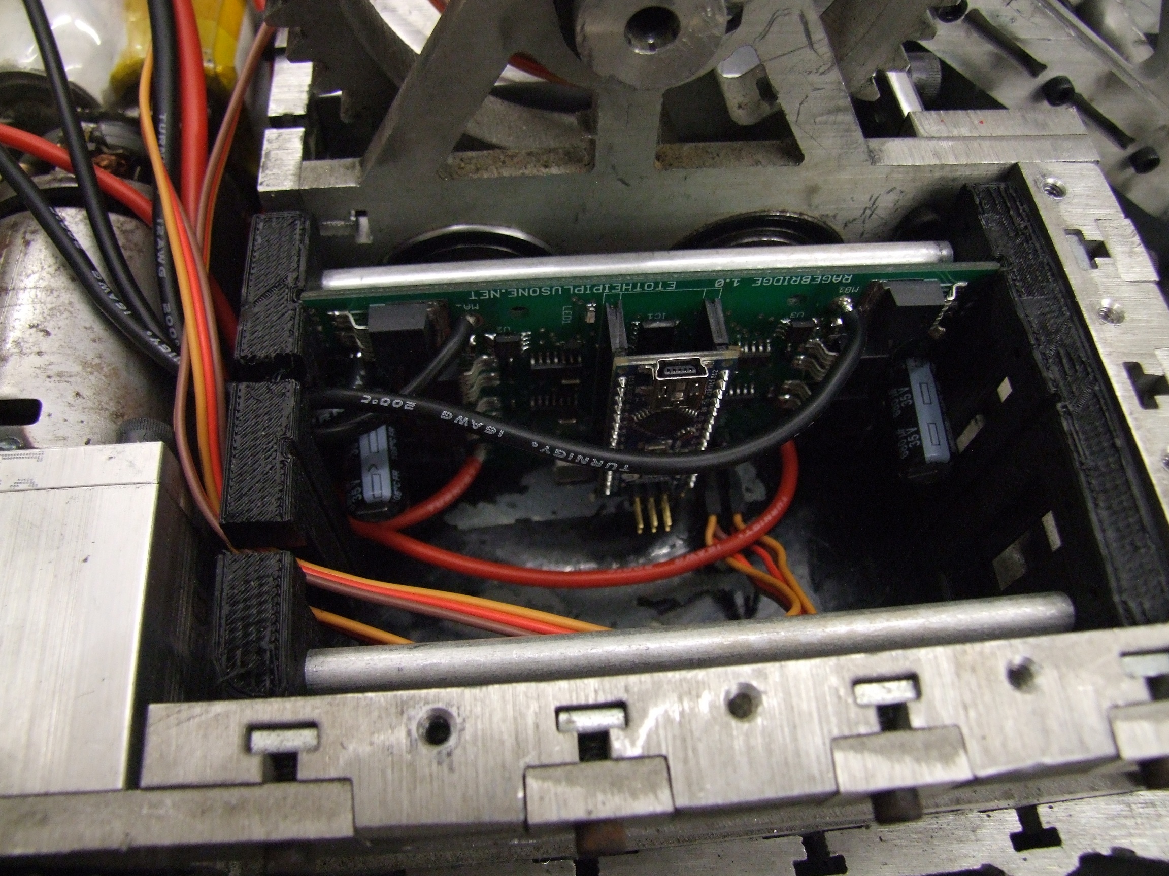
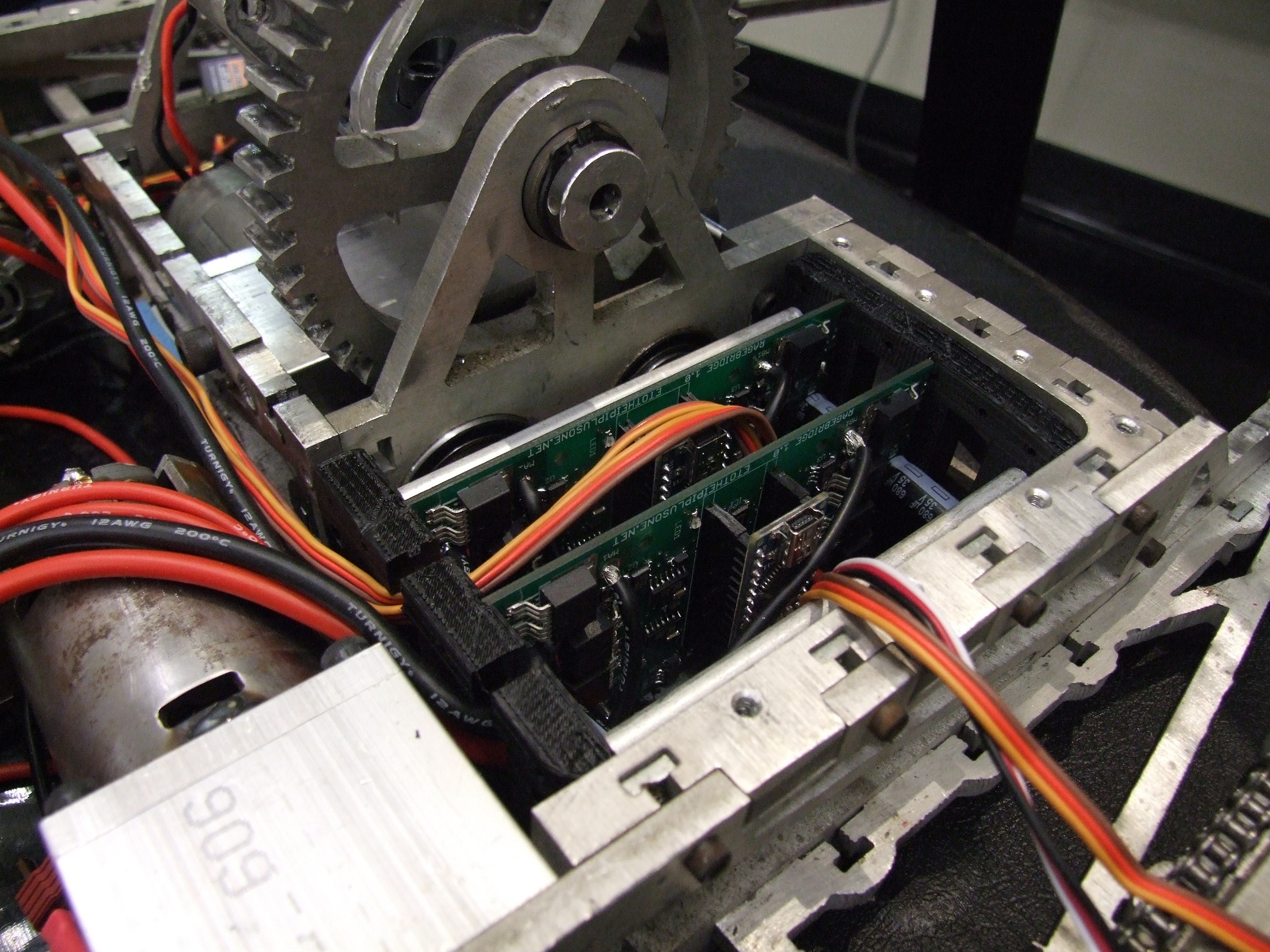
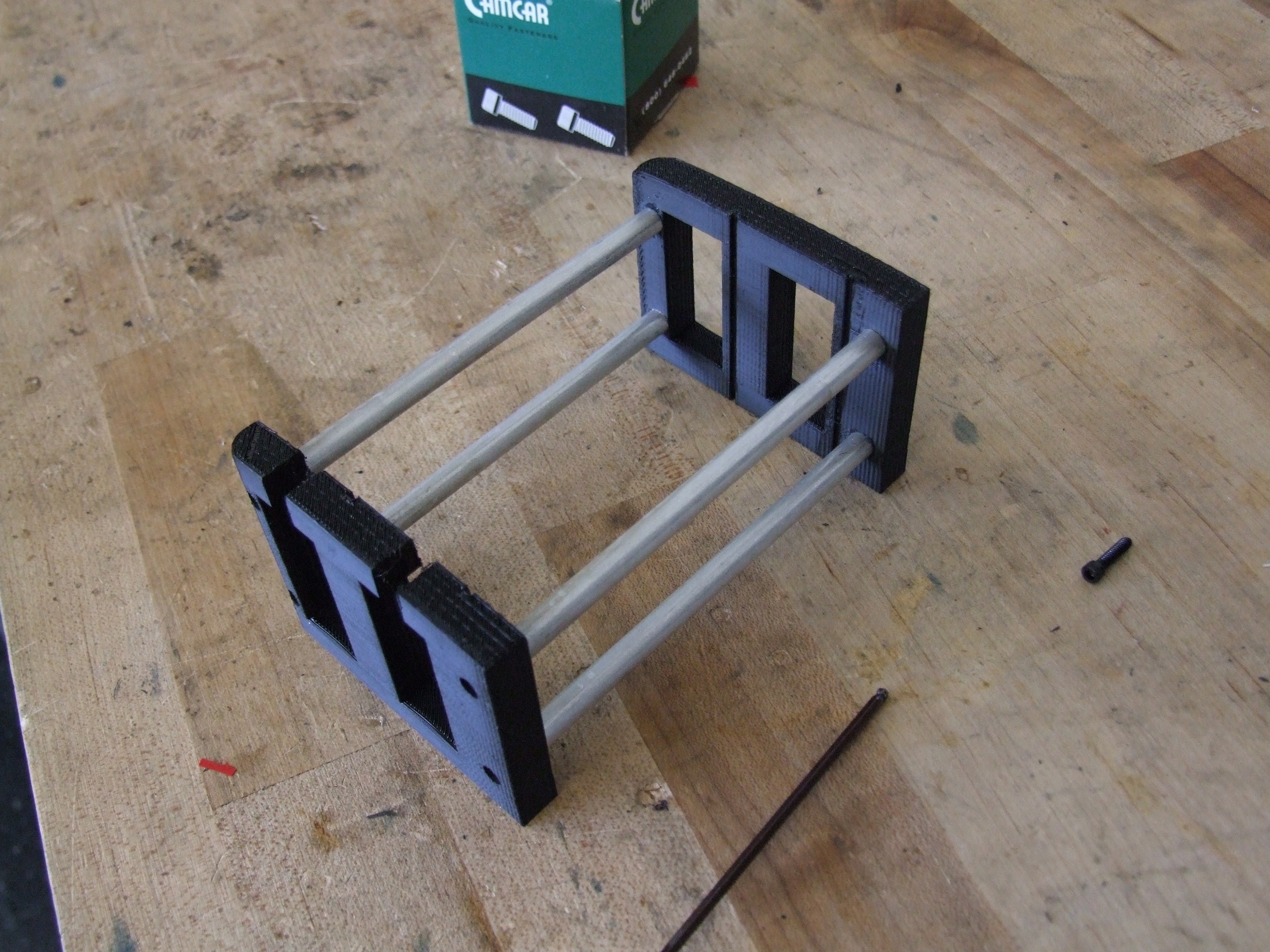
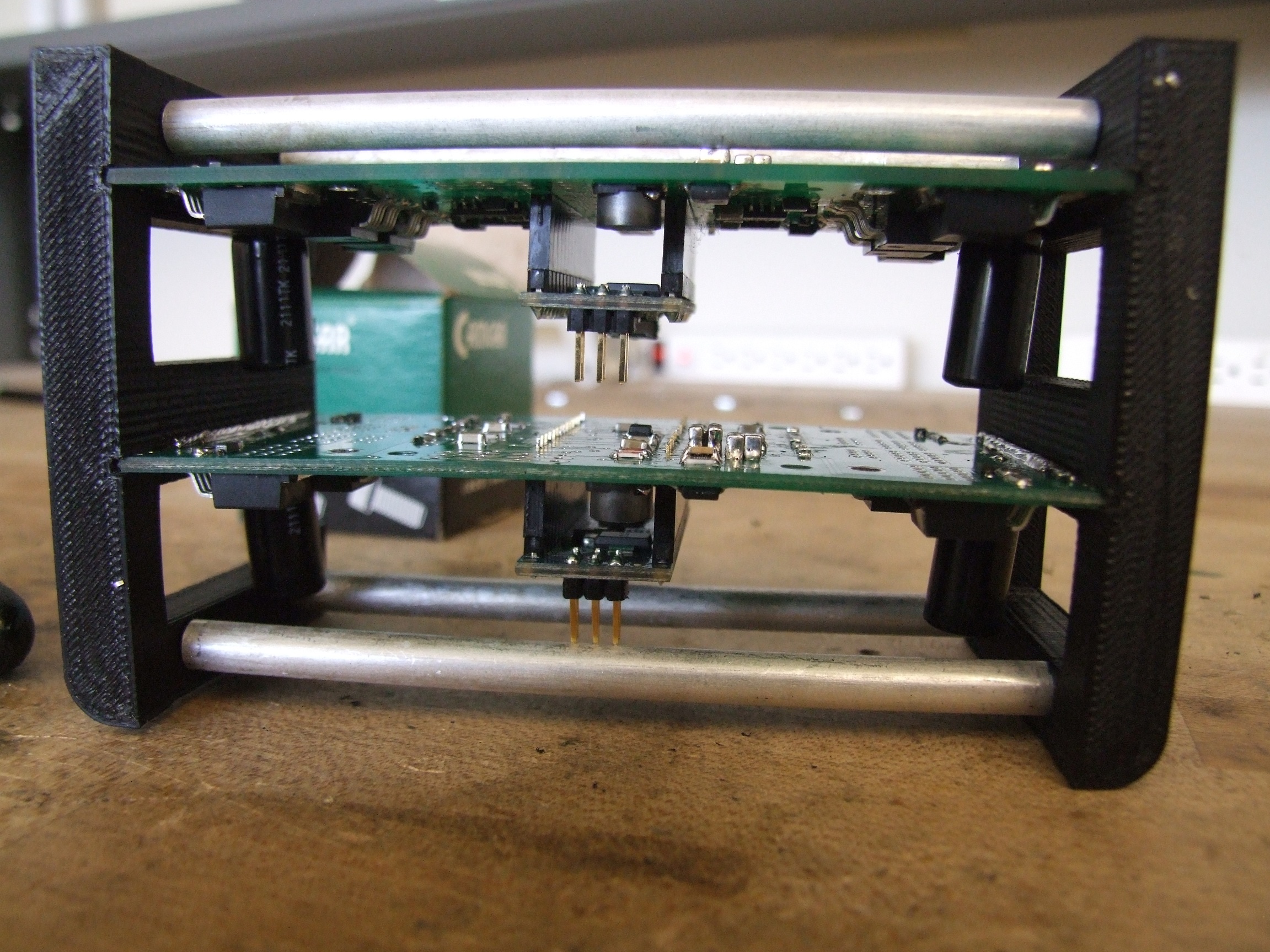
Then I realized that the boards are just short enough to mount vertically. I still needed a way to retain them, though, so cooked up very quickly this “rack” that has slots which the boards fit in.  This was whipped out on the Lab Replicator™ and the standoffs made with a lathe.

First tries always reveal where parts run into eachother. On the upper board, the capacitors on the underside touch the standoff above them. And on the lower board, the Arduino Nano’s ISP headers touch the standoff below them.

Hmm.

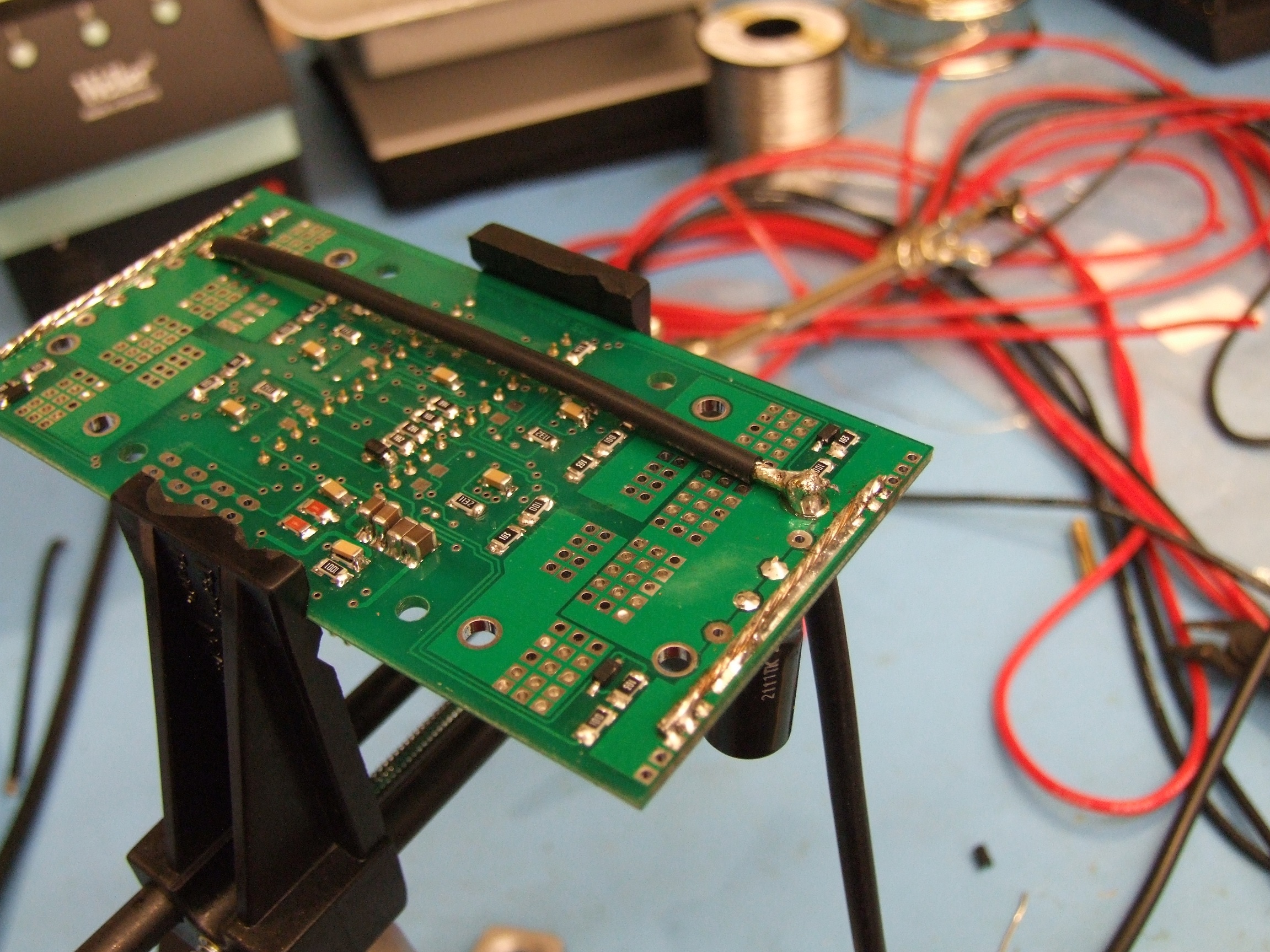
The second revision moved the boards a little closer together and away from the standoffs. With the mounting solution taken care of, it was time to attack the boards themselves. I first had to attach wires to them:

Instead of soldring wires to both battery inputs and then joining them in parallel, I used a single 12 gauge input wire and then a 16 gauge ‘jumper’ which brought power to the other half of the board. The constraints of rack-mounting my controllers this time meant I couldn’t make big Y-cables.

After populating the boards, I began to run into regulator drama yet again. With my Spektrum receiver (Clocker’s receiver for 3 years now) attached, the LM2594-based switching regulator wouldn’t. This was worse than it was on Null Hypothesis (details in the middle) where it seemingly had a habit of not wanting to power cycle. The 15v rail was totally unstable, and the 5v power LED on the Arduino nano would flicker as the regulator kept latching up and resetting.

Even with the Arduino Nano but no receiver, it was still erratic, taking several seconds to stop resetting the microcontroller. The whole time, the regulator was also getting hot. Extremely hot.

Both boards displayed the same symptoms. When the regulator was in latchup mode, the switching frequency was audible and also very unstable. Basically, it seemed that any load was causing the whole thing to go crazy. I began attributing it to being a design error on the board or in the layout – maybe I had crossed my grounds somewhere else?

I began pulling desperate hacks suck as capacitance in places where it really should not have needed capacitance (i.e. where a slightly out of spec component value should not have a first-order effect on functionality), and even hacking a 7815 linear regulator onto the board to test if it worked at all (Result: Yes, the board itself is fine, and the linear regulator would be also fine if I wasn’t wanting to run 30+ volts).

Defeated for the night and about to switch Clocker back to Victor 883s, I read once more through the datasheet hunting for possible thermal limitations or some indication that I had totally fucked up the component layout and selection. The datasheet had a section on inductor selection, which I’ve handily ignored in the past. Within it was this equation:

Okay, sure, let’s try it… For my setup, with Vin = around 25 volts and Vout = 15 volts, I got a V-us value of 38. Now let’s see the inductor selection table:

Oh dear.

For as long as I’ve used the LM2594, I’ve just tossed a 100uH inductor onto it because it was cheap on Digikey for the package size I designed with initially. And for as long as I’ve used the LM2594, it’s always been a nervous wreck.

My voltages and load clearly put me in 330uH territory. The microcontroller and receiver combined generally draw 50-70mA combined, with the beefy Spektrum receiver demanding 100mA when it is searching for a transmitter. So for the purposes of modelling, 0.1A is a good number to use for load current.

So what does too-small an inductor do to the system? Several possible things. First, current can change (ramp up or down) faster – there’s less “mass’ to it, so to speak. Second, as a result, the regulator can enter “discontinuous” mode, where the energy needed by the load per switching cycle results in a duty cycle so small that the current (which can now change faster) falls to zero instead of continuing to flow (“continuous” mode). The LM2594 should be able to handle discontinuous; but next, because the current can change faster due to the inductance being too low, it could very quickly reach a level which throws an overcurrent fault in the LM2594 regulator. In other words, it wakes up, turns the inductor on, goes OH FUCK, enters shutdown, wakes up, turns the inductor on, goes OH FUCK….

This really all speculation, but the observation that most supports the inductor-too-small theory is the fact that the LM2594 only reduces its switching frequency if it is in the overcurrent condition. I shouldn’t be able to hear it otherwise. I tested this by finding a voltage input which would run comfortably at 15v out and 100uH – about 17 to 18 volts seemed to do it. And there were no problems whatsoever. As soon as I crested about 20-22 volts, though, all hell would break loose.

Well then.

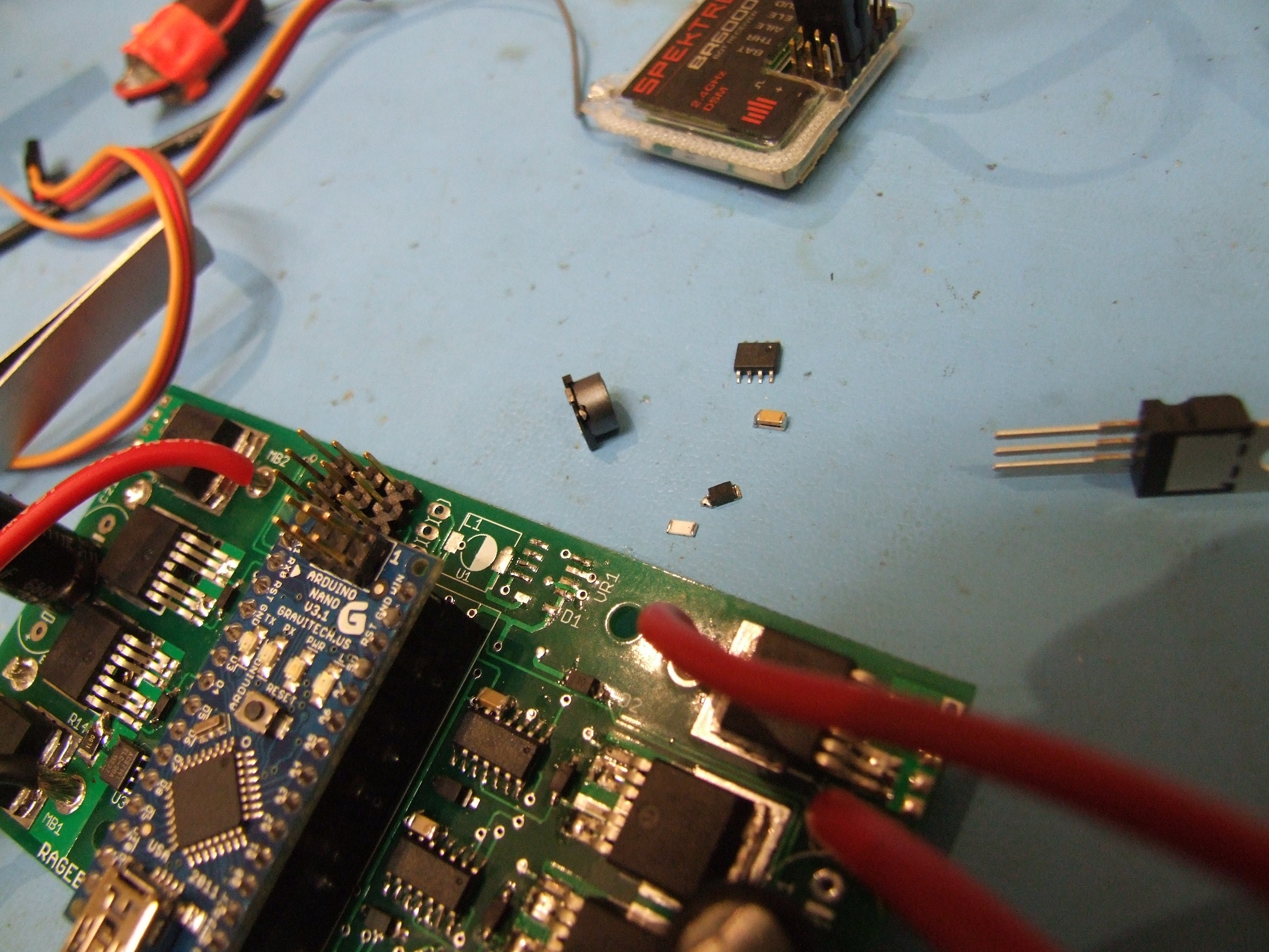
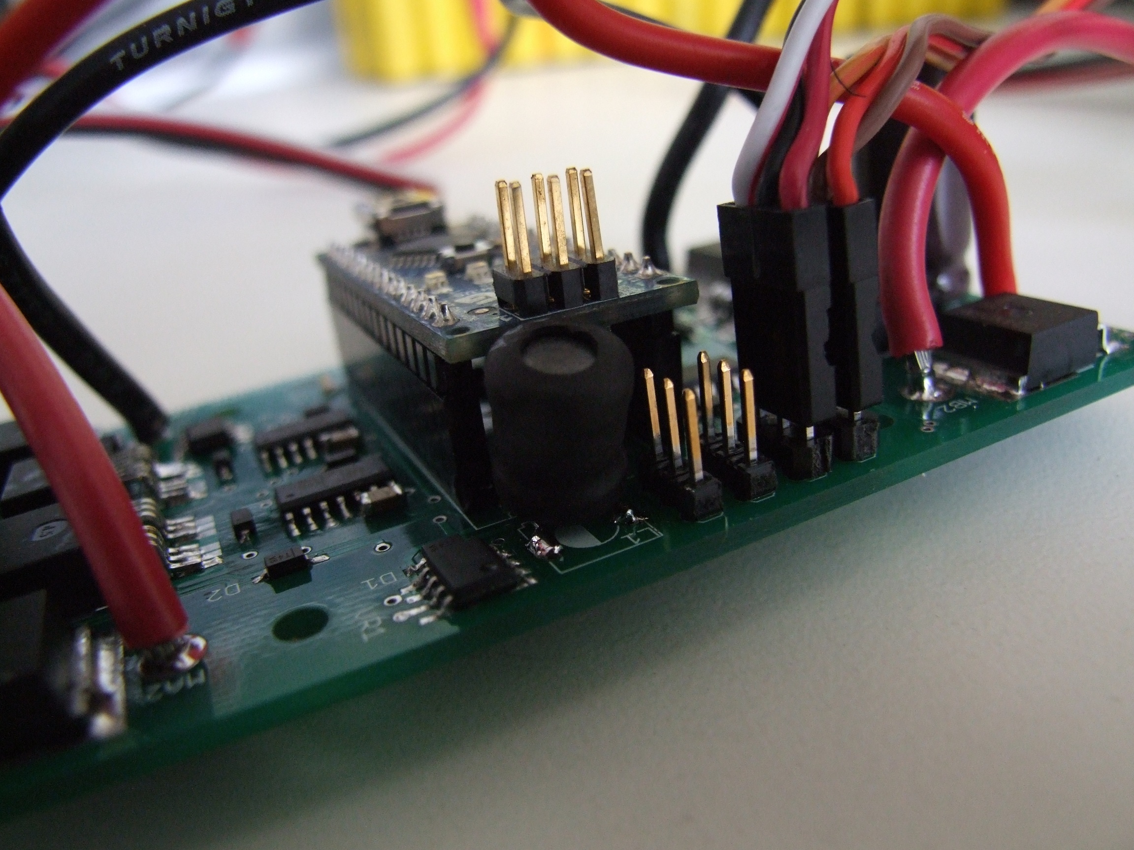
Could I have been defeated by just not reading the datasheet? Let’s find out. Luckily, I had some 330uH through-hole inductors left over from the construction of Segfault’s controller long ago:

Through hole, surface mount, same thing… just some bent legs.

This was the only change I made to the whole regulator circuit – all of my other hacks had been undone by this point, because I wanted to make sure there were no other layers of mods that needed to be made. Surely just an out-of-tolerance component value cannot be the root cause of my controllers’ undoing!

Except it was.

Whatever, I’m just gonna stuff it in the robot.

I’ve yet to experience another hiccup or reset since replacing the inductor. At all – the only thing which causes a reset is a sudden applied load on the logic side – plugging in the Spektrum receiver when the board was not doing anything previously, for instance. In *that* case, certainly more buffering capacitance could help, but if the receiver is suddenly plugged in during battle, something has gone very, very wrong.

I test drove Clocker for a few minutes in this configuration (only the drive – the other controller isn’t installed) just to test the robustness of the fix. This test included several power cycles both “hot” and “cold”, to see if the thermal issue could have been part of the problem. The regulator does still get hot, but it seems to be a normal hot.

It’s time to install the next board! By this picture, I had already pulled the 100uH inductor off every single Ragebridge board current in existence and replaced them with the 330uH thru-hole ones. I was now test lifting various chairs and handtrucks with Clocker.

Playing with the current limit setting, I got the main output gear clutch tuned to the point where the bot could quickly lift 30 pounds on top of the fork, but if I stalled the fork against the frame, there wouldn’t be enough current to do any damage. The way it was accidentally tested was by wiring up one lift motor backwards so the two motors were fighting eachother the whole time, while I stared dumbly on and went “Hmmm, I wonder if something’s jammed”. I am vaguely glad for the existence of (my and only my) current-limited controllers.

The prescribed current limit for the fork is 30A, at which point the two motors will produce 50lb of upward force at the tip of the fork.

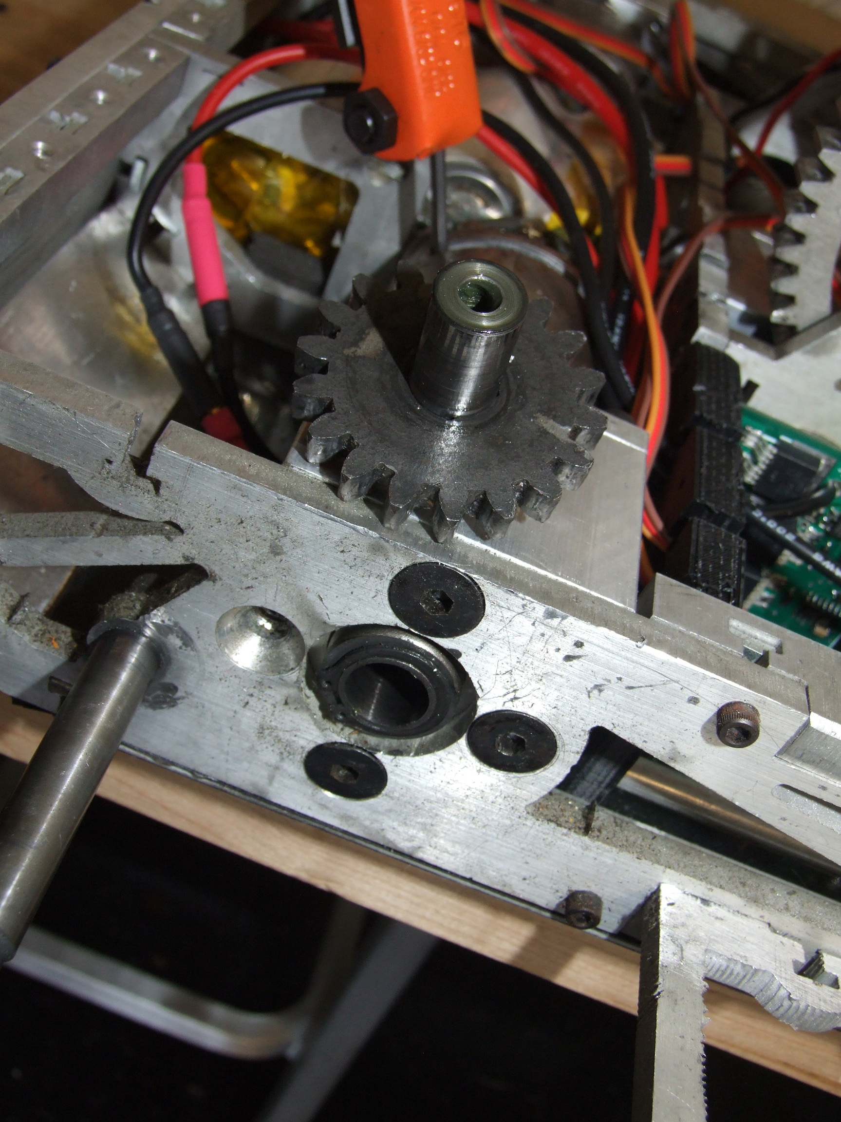
Alright! I’ve fixed the electrical problem, so let’s bounce the problem back to mechanics. That is my right side output gear, not being where an output gear is normally found.

How did this robot *ever* work?

Remember at Dragon*Con 2010, the left-side output shaft of my custom DeWalt frakenboxes lost its shoddy press fit, leaving the bot mostly immobile. That side was repaired by knurling the output shaft where it meets the planetary gear carrier, and it hasn’t been a problem.

I’ll admit that the discovery of this problem was just a little unconventional:

Hey, if it has a current-mode, I’m riding it, okay?

Definitely a useful way to stall-test your drivetrain. Each drive side’s current limit is set to 55A, which actually seems kind of low for the DeWalts. They definitely want more when spinning up. Maybe I should have double-bypassed the current sensors to get peak 90A limits, but then I’m pushing the board’s physical layout in terms of current density in the copper layers.

During some enthusiastic turning, the right side suddenly stopped producing torque, and I heard the dreadful sound of “motor spinning up unloaded”.

How did this robot EVER work?

Clearly the answer is it never really worked, if I’m hammering out one problem after another. I repeated the knurling and re-fitting operation on the right side, and all was good.

Now let’s return to the electronics.

During another driving and lifting stress test, something exploded in the bot.

Crap. It’s already like 3 in the morning by this point, and I’m wondering if now that the fundamental disability of the controller has been solved, the problems have moved down the line to the next weak link. Now, the controller that bit it was the drive controller, a.k.a the one I did all the nasty experimentation on before finding the inductor issue, so maybe it’s just weakened from being an experimental subject.

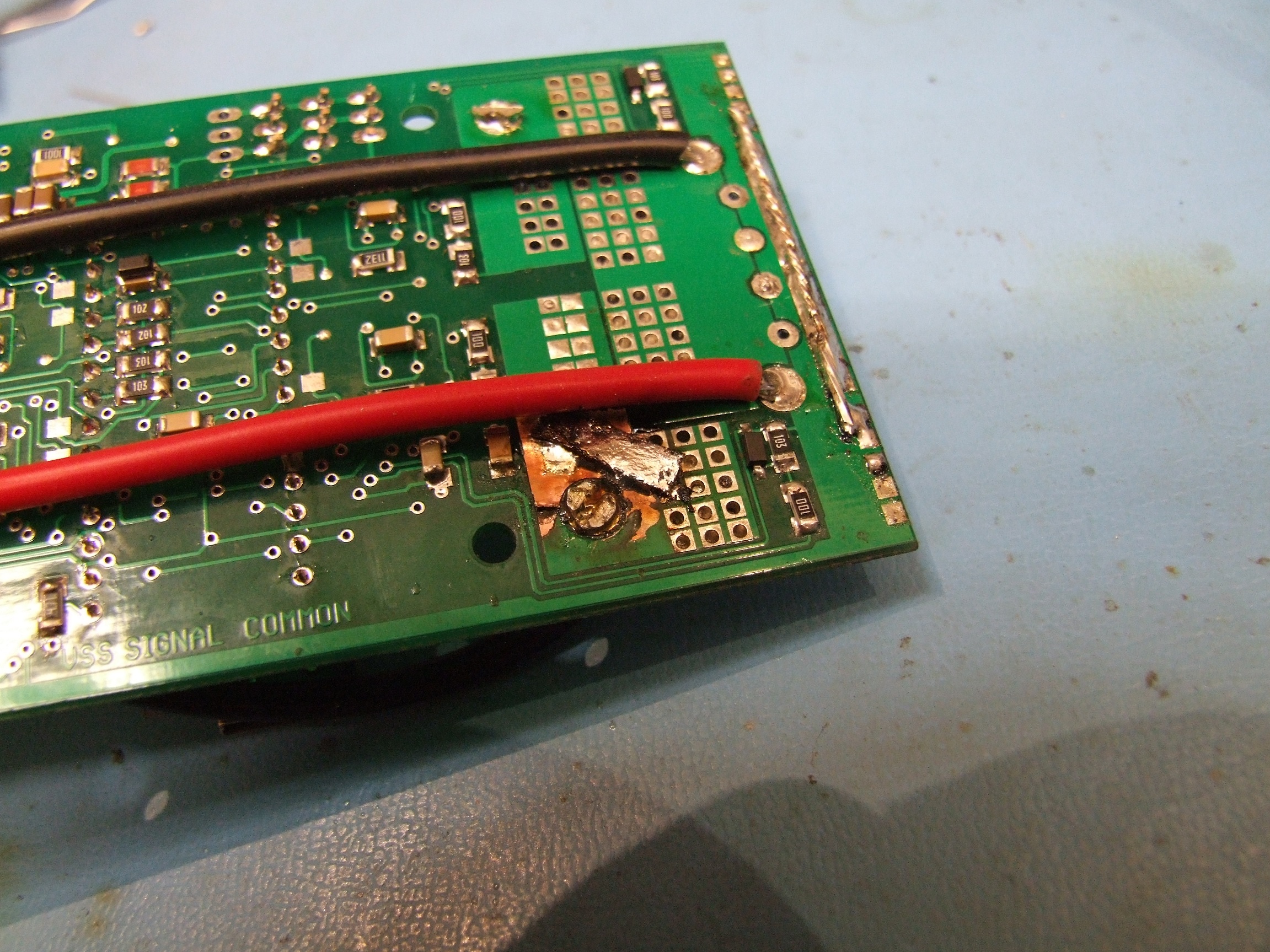
The failure was just indicative of massive shoot-through. Aren’t my gate drivers supposed to prevent that? What could possibly cause the FETs to suddenly overlap with disasterous consequences, besides like, leaving half of the gate drive chip unsoldered because I forgot to go back and solder all the pads after anchoring it?

Oh, it was that? Okay, carry on.

Here’s the final wiring arrangement for Clocker. It looks kind of like the same jumbled mess as it has been, but the wiring runs are alot better packed.

I made another spare battery afterwards, because this pack is getting high in years (and in number of dents in the cells – a little disturbing). Not only that, but Clocker has no less than 3 550 class motors and two DeWalt motors now, so it’s more stress on the battery than ever. It’s not going to run back-to-back matches for sure, so I need to have a swappable battery.

Here’s the bot all closed up for this year!

And now, a bit of test video, showing some more handtruck yoga.

So that’s where all those dents in the cells are coming from.

And here’s a shot of the 2012 fleet: Null Hypothesis and Überclocker Unicorn. Sorry, the nickname just kind of stuck – and it was also partially inspired by the fact that Gundam Unicorn is a real thing.

So that’s it. 30lbers only this year for me, with none of the ants and beetles returning. Instead, I have become the arena; more on that later!

Dragon*Con 2012 Schedule

Observant attendees will notice that I am a panelist in the Robotics & Making Things & Engineering & We’ll Find a Snappier Name For This Next Year track. It’s been a long peeve of mine to go to conventions only to discover that all the panels suck, so I’m out to fix it. In the past 2 years, I’ve been complaining that nobody really had a panel focusing on the where to get and how to use (not to mention the even go want to do look more like) – the resources of engineering projects, which for me at least was perhaps the number 1 contributor to actually being able to get nice stuff done. What to buy, where to buy it, where to scrounge and salvage it if you can’t buy it, and why it doesn’t work the way you think it does.

So I’m proud to announce the MAKER RESOURCES panel, which will probably be something like all of my Instructables slammed into an hour. Focusing primarily on parts procurement and fabrication resources for the non-shop-endowed maker, I’ll also touch on design software and design methodologies.

Next is the ELECTRIC VEHICLE TECH panel, co-hosted by real EV guy Adam Bercu. My role on this panel will probably be dealing with the smaller end of rideable objects, discussing the nuances of using hobby R/C parts and shitty e-bike controllers. We’ll likely cover basic EV drivetrains and power system choices as well as math for estimation and calculation of drivetrain properties. Basically, 2.00scooter in an hour except probably more 2.00motorcycle.

I’ll also be on the DIGITAL FABRICATION AND WATERJETTING panel along side long-time robot buddy Simon Arthur (some of you may know him as Big Blue Saw), in which we’ll touch on ways to abuse the waterjet and laser cutter, and the coolness of digital fab in general.

The 1100-mile haul begins soon.