


I hate designing motor controllers.
So that’s totally why I designed a new one, right?. But before I get to the pictures, let’s discuss the circumstances of Tinytroller’s creation.
Melontroller 2 is my current “stable release” Arduino based 3 phase motor controller. It’s been powering RazEr Revolution now for most of a year with no trouble, right up until I killed it by being an idiot while trying to change some of the code. The only electrical design downsides to it was the fact that I had to make a little blue wire hack because some of the pins on the Arduino Mini were connected incorrectly, and it also required (for some reason) a common mode choke on the main power inputs. But for another step in my quest to tame the brushless motor, it was very functional. Its current carrying capacity was well matched to the Dual Non-Interleaved RazErmotor, and I never had thermal problems or burnouts.
And it had an earsplitting 4khz PWM frequency, but I found out how to fix that. For what it’s worth,
  TCCR1B = TCCR1B & 0b11111000 | 0x02; //Set prescaler for 3.906 Khz
  TCCR1B |= (1 << WGM12); //Set fast pwm for ~8khz
  TCCR2B = TCCR2B & 0b11111000 | 0x02; //Same operation on Timer 2
  TCCR2A |= (1 << WGM21); //Same operation on Timer 2
…is how you get 8kHz PWM on an ATmega328. On the Arduinos, this translates to pins 3, 11, 9, and 10.
There were two more unsatisfying aspects of Melontroller 2, however. Number one is that it was still too big. I just designed “a controller”, not a small controller or a controller designed specifically to be mechanically mounted in a vehicle. It didn’t fit in RazEr except at an angle, and only when I belt-sanded the edges down as close to copper as possible. So, I wanted a smaller footprint for the next version – it’s always fun trying to see how tight you can mash your traces together. The other aspect is tied closely to the board being large – it’s still single board. I’ve been wanting to move to a signal + power board stack arrangment, since that decouples the logic and gate drive from what the output amplifier actually is. A majority of commercial controllers – R/C or otherwise – have an independent signal and FET driver board that can be dropped onto a power board of varying amperage capacity, the result being sold for varying amounts of markup. Moving to this architecture would allow me to insert ridiculous semiconductors into things without having to redesign an entire board from scratch. Experimentation!!
Additionally, Melontroller 2 was designed to use a Sparkfun Arduino Pro Mini. This is actually perfectly fine, but the current standard around here is the Gravitech Arduino Nano, since it is being used for the 2.007 Design and Manufacturing class. The nice thing about the Nano, despite being more expensive, is that it has onboard USB. No more diddling with FTDI or other (apparently pin-incompatible) USB to serial converters. This isn’t a “design problem” so much as a mild inconvenience. For future designs, though, I wanted to use the Nano.
Oh yeah, and finally a switching regulator instead of a power resistor puking into a linear regulator.
The real deal-maker for me to get moving on a new controller was the Hobbyking cartroller. This thing was an Arduino short of what I had in mind already but just didn’t want to start designing yet (because hey, Melontroller already works). I wanted a higher voltage Hobbyking cartroller, one that could reasonably run 36 to 48 volts, the voltage of most things I build. So, the goal was set: A 36-48v, 30-40 amp controller in the space of a HKcartroller or smaller, with current sensing that I promise I will use this time and nice FETs and all that stuff. Essentially this amounted to cutting Melontroller down the middle and moving the Arduino half upstairs.
design

I started with the power board design, since power layout is always fun and I already knew what the signal board would look like. I wanted to try one more thing with this design too: a totally flat bottom. Melontroller features components on both sides of the board, which is fine, but the D2PAK FETs are facing the wrong way for good heatsinking. Their thermal resistance to the plastic case is substantial, making heat sinking kind of moot. With the burden of jumping power and signal connections to the power board relieved, I could move everything to the upper side of the board and leave the bottom as only copper. I could then use some silicone padding and bolt the whole thing to a brick of aluminum and be done. Granted the board is not fully one-sided – the through hole parts on the edges still stick down a little.
The FETs are my default IRF crackFET, the 3107-7. Infineon is slowly drawing my attention away from IR because their 75-80 volt D2PAK-7 crackFET seem to have lower gate charges, but they are far more expensive.

After a night of rage-routing, the power board is done. The final outline is 2.1″ x 2.1″, with 1.9″ square mounting holes. The via fields are for conduction between layers, both current and heat. I had to pull some topology tricks running bus traces under and over eachother, but all the motor connections ended up on one edge and all the power connections the other – another improvement over Melontroller, which did some kind of weird right angle thing. Gate drive header is on the bottom, giving access to both gate pins, the phase output, and ground. The current sense header is up top.
I’m electing to use the ACS714 sensors again – the same ones, in fact, on the original Melontroller since I never actually involved them in any kind of feedback loop.

The signal board is the next floor up. The IRS21844s gate drivers and 15v gate drive and logic supply (now with LM2594HVM switching regulator!) are located on this board. The Arduino Nano is technically another board, so does that make it some kind of 2nd floor mezzanine lounge?

Here’s an example of what I mean by random semiconductors. This is the footprint I made for a Powerex CM200TU 3 phase “brick” IGBT module.
It’s very tempting (ignore the potentially 10+ microsecond switching times and lack of negative gate drive supply for a minute here).
fabrication
Because I wasn’t in a hurry to debug yet another motor controller, I sent Tinytroller to MyroPCB for fabrication. Myro has some perks – panelizing is not very expensive, and you can get soldermask in blue and red if you wanted. However, it just takes longer and seems to be less certain in shipping deadlines than Advanced Circuits, my usual board house.
And their ordering and quote management system sucks. Like seriously, it is terrible. It reminds me of something which ends up on The Daily WTF.

Two weeks later, it returns. It’s nice, and also very blue. I manually panelized the signal and power boards onto one file with 4 complete controllers, so the numbering is way off on all of them but the original, but I’ll figure it out. Shown is one melontroller for scale.
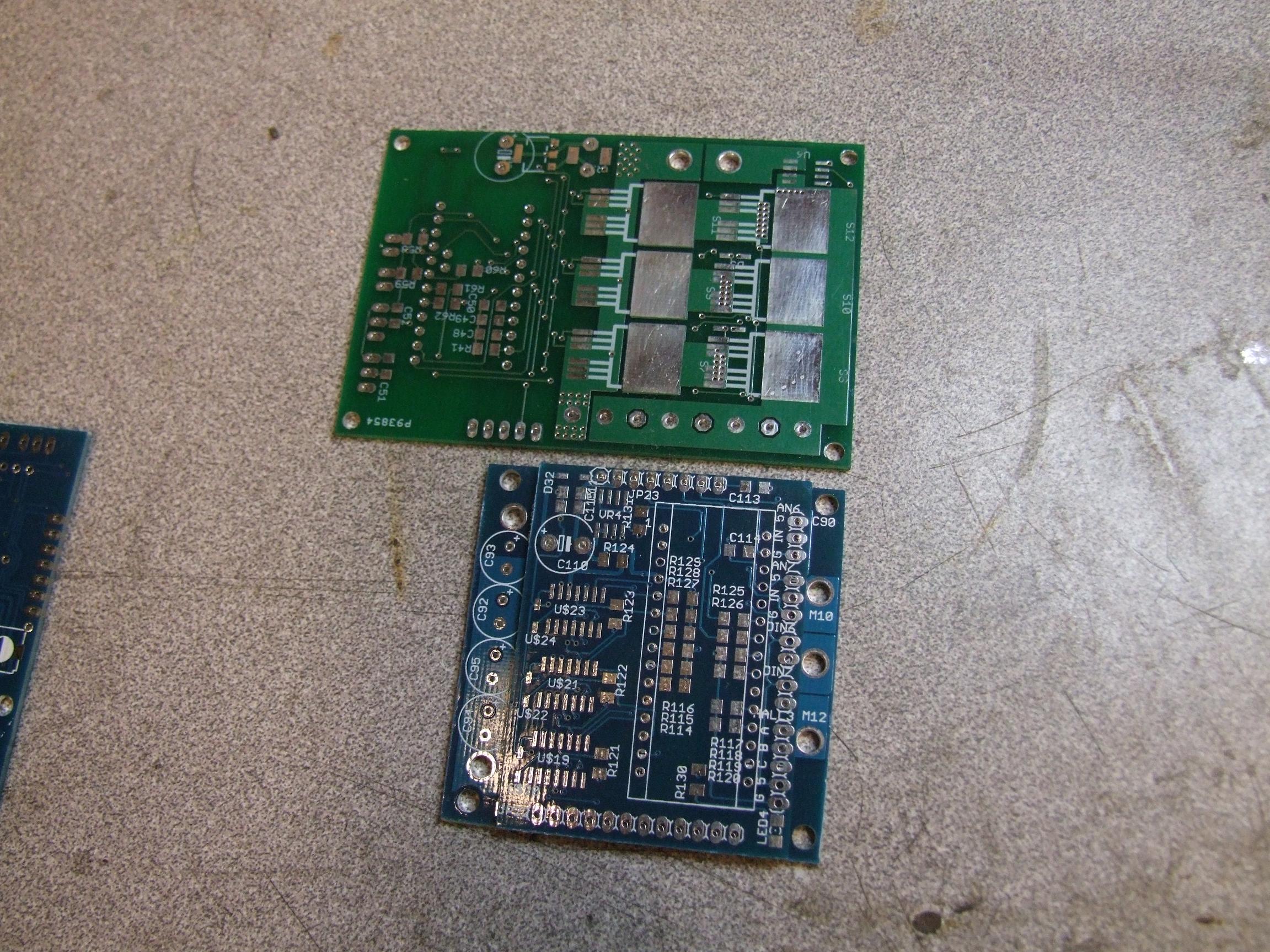
The cool part is when I split the panel off and pile the signal and power boards on top of eachother. The footprint is about 60% of a melontroller.
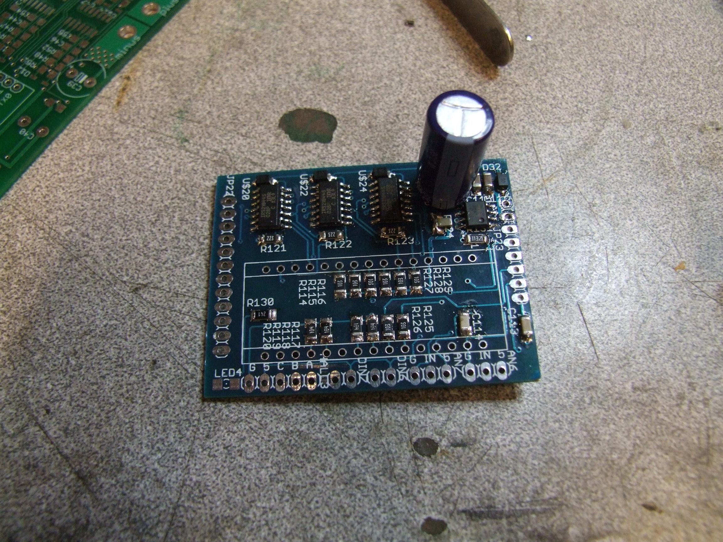
By this time, my Digikey order of parts has gotten a little stale already, so let’s start assembly. I like the way the passive components lined up on this board – close to the microcontroller pins and all in a line. The resistors are either pullups and downs, or part of RC filters. All the capacitors are on the lower side, directly under the resistors.
Excuse the ridiculous logic power buscap, since I literally had no smaller ones at the moment. When your logic board sparks on plugging it into a power supply, something’s wrong. In a future version, I might move to an all-ceramic logic power capacitor bank since the required capacitances are much smaller.
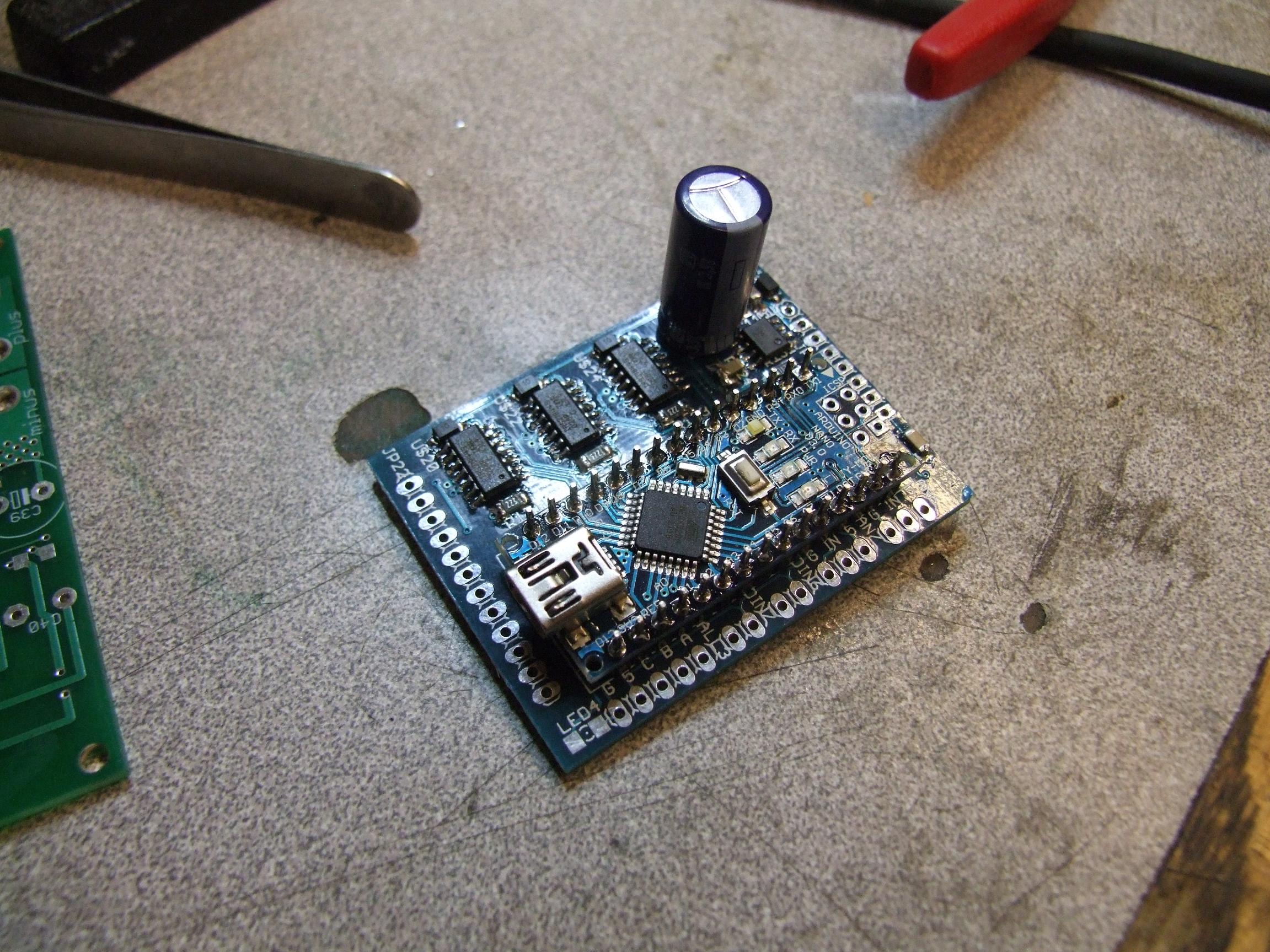
Now With More Arduino! The Arduino Standard Color is actually blue, so it’s pretty appropriate for an Arduino brushless motor controller to be blue colored.
For some reason I decided to hard-solder the Nano onto the board using only a standard male header row as a spacer. This turned out to be a bad idea – the Nano has parts on the underside, and I got a slew of shorting problems as a result.
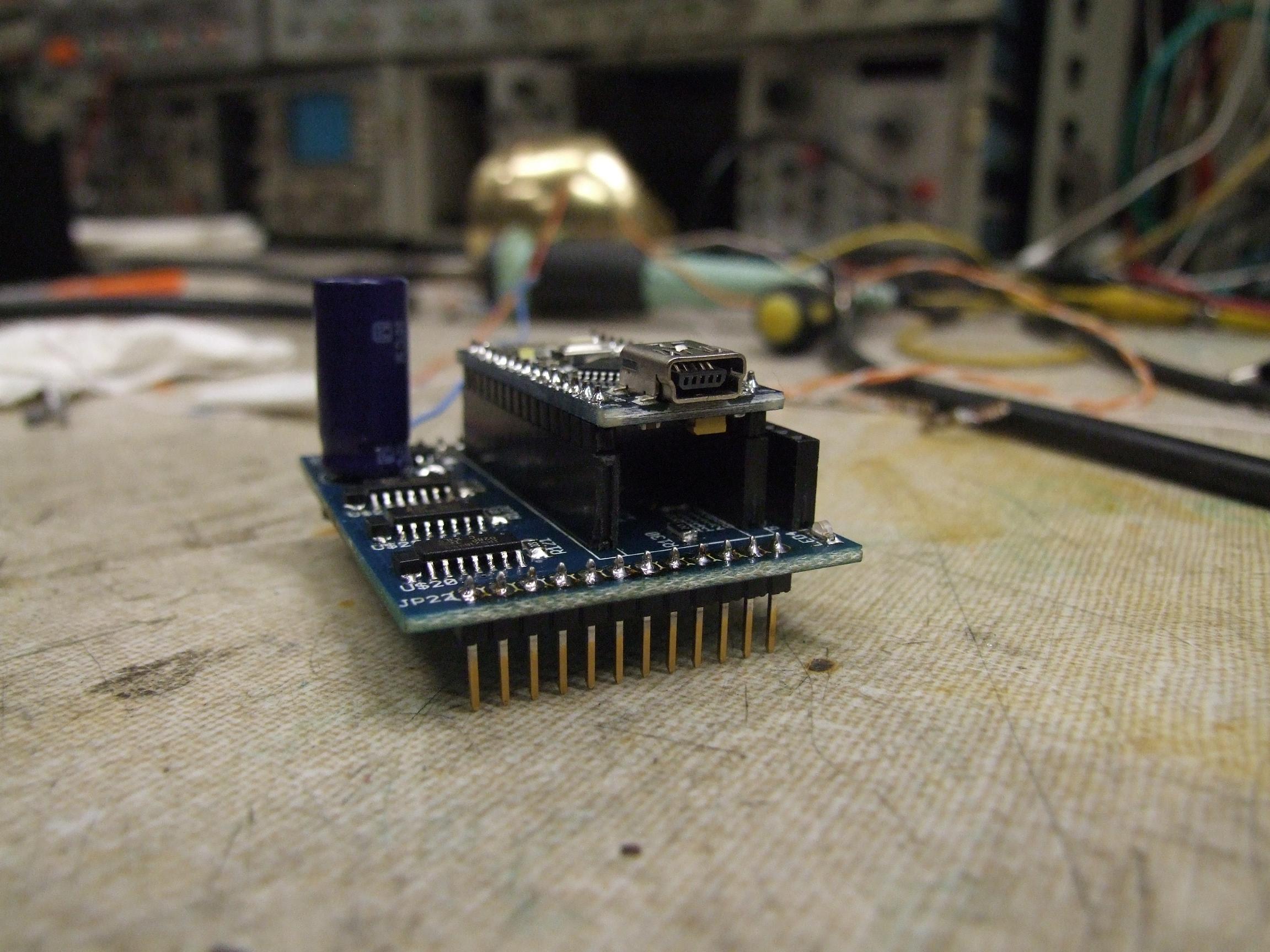
I had to heat gun the board off – it’s likely permanently damaged from shorting and heat gunning and screwdrivering, so I’m only keeping it in case the ATmega328 still works. I had a spare Nano to replace it, which I put on a set of female headers for easy mounting and less terribleness.
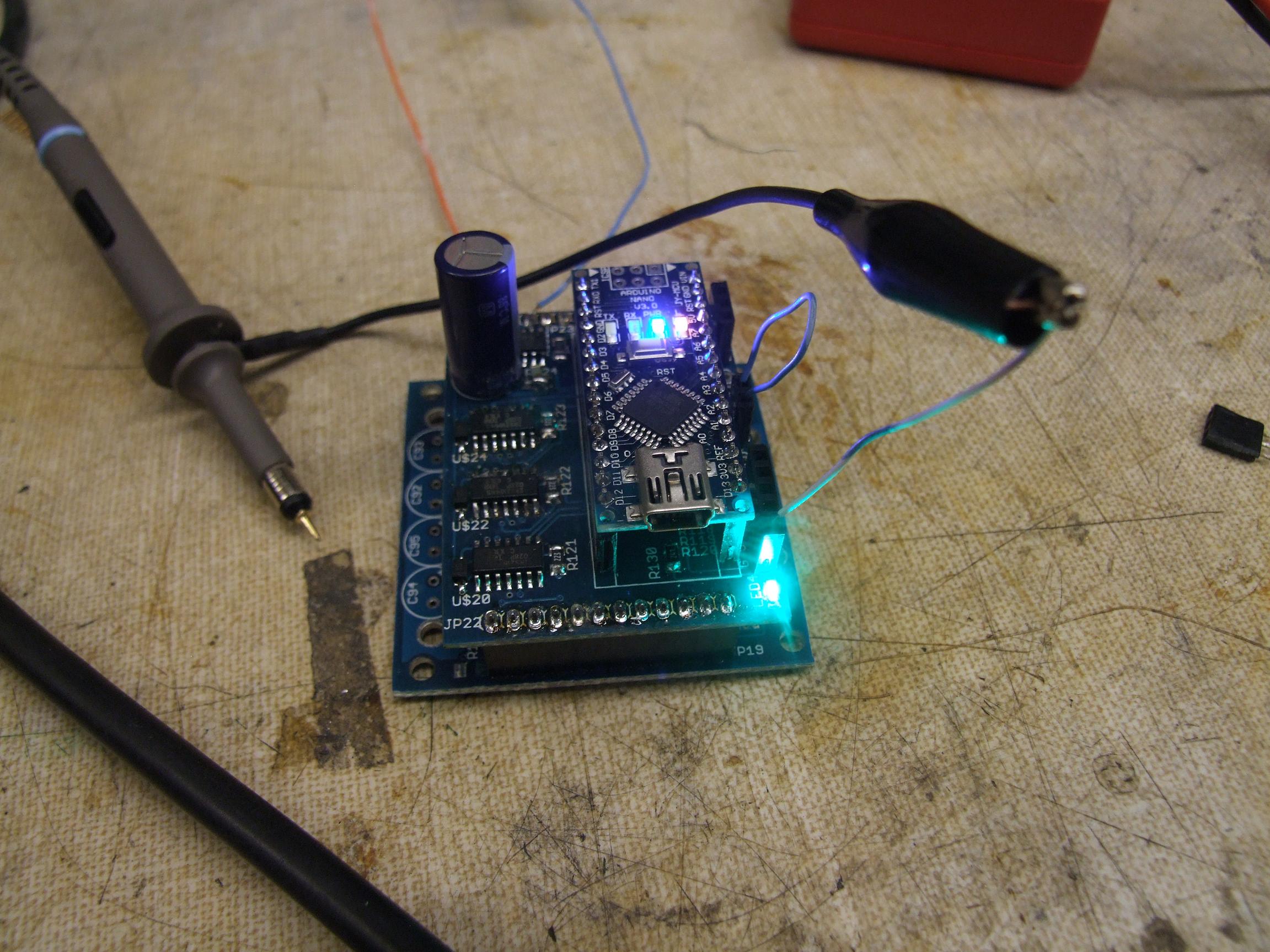
A test confirms that yes, I have successfully made a 15 volt regulator. I tried to test the gate drive at this point, but with the power board disconnected, alot of assumed common grounds were not present yet, so it didn’t quite work out correctly.
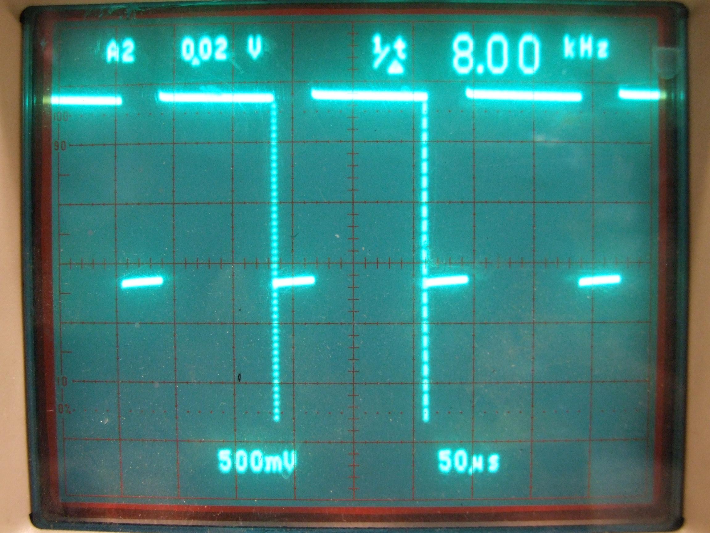
Only the low side of the 3 half-bridges, connected to main power supply ground, could switch and be viewed on the scope. I doubled checked that yes, my register diddling had indeed worked and pins 9, 10, and 11 were outputting a solid 8 kHz.
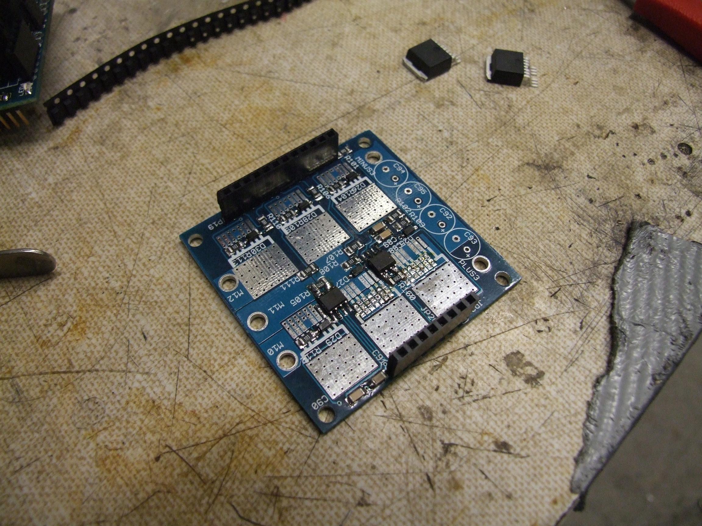
I started the 3 phase power board assembly by mounting the small, bitchy parts first – the current sensors and assorted passive components.
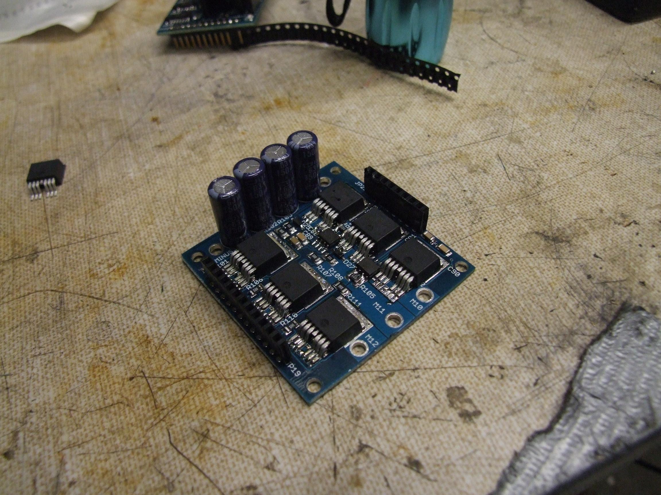
Now it’s getting serious. I soldered the FETs conventionally first, but then turned the board around and made sure the vias were filled in. Otherwise, a hollow copper shell isn’t much good at conducting either current or heat.
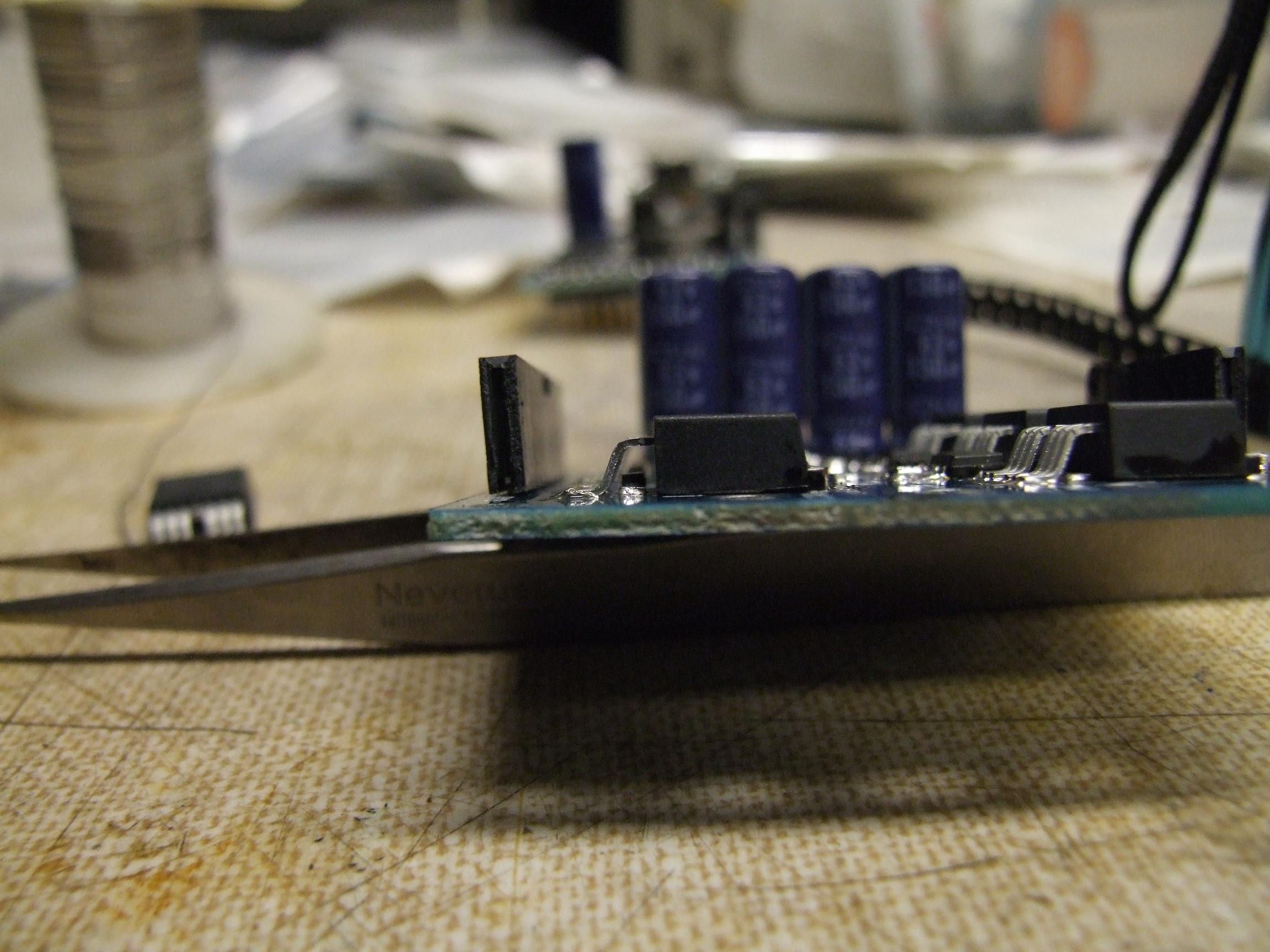
Something very experimental I tried on Tinytroller’s design was placing gate drive passives under the flying legs of the D2PAK. It turns out you can fit a zener diode and entire 1206 resistor under there, possibly more if I used smaller SMT parts. This compactified the gate drive layout significantly – under each FET (except the left two on the top row, since trace hopping precluded it) is the protection circuitry – a 17 volt zener diode and 10K pulldown resistor.
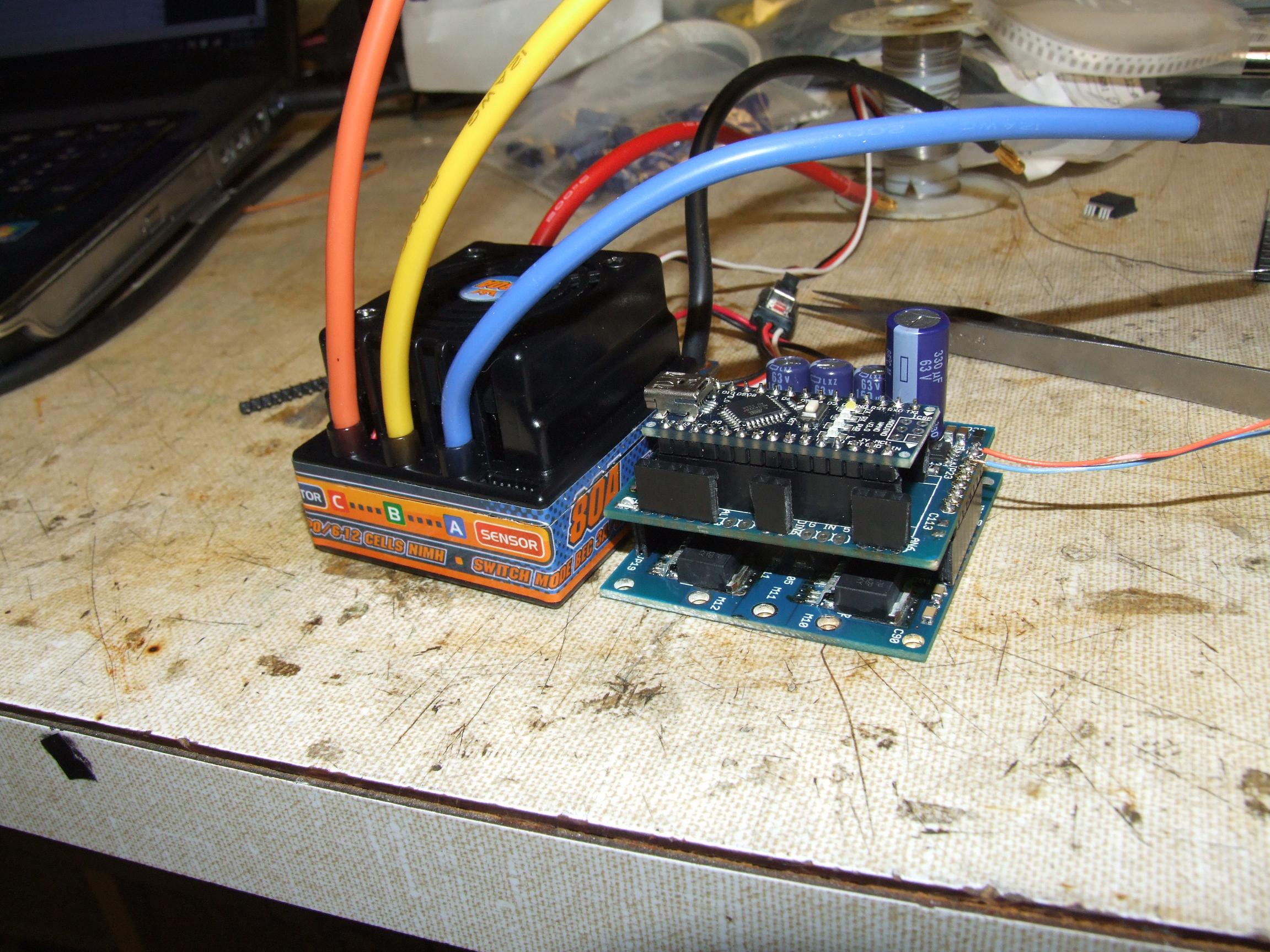
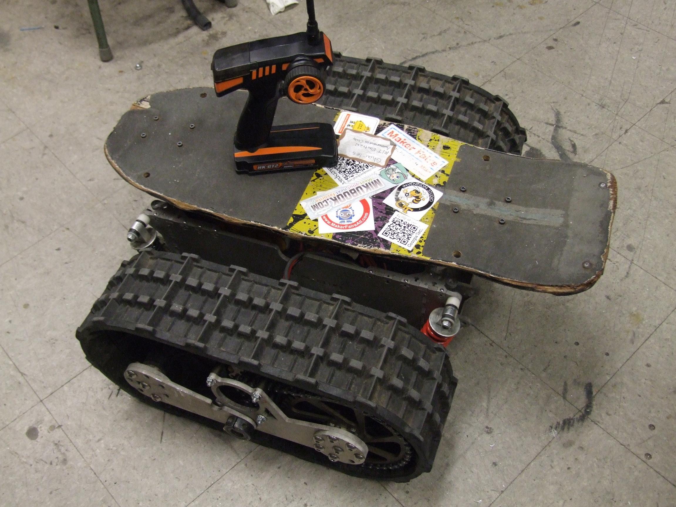
The completed assembly next to its benchmark. I think I *just barely* win, but I don’t have a nice case or anything… This was the HK cartroller I detonated while trying to time the motors of a certain wobbly treaded skateboard thing. For a brushless ESC with an entire Arduino on it, it’s still pretty small.

With all of the FETs mounted, I could actually check out the gate signal on each of them. The switching time seems to be around 200 nanoseconds, which is making me question why my deadtime is set for a solid 1 microsecond. Seeing this makes me want to try shorting the 21844 DT pin to ground – which should result in a natural 400nS delay.

Because the HKcartroller was toast anyway, I stole the nice 10 gauge silicone wire off it for testing. Now this thing looks even more like a Hobbyking product.
Tinytroller is now ready to take a stab at the MITERS Public Etek once I write the commutation code. I’m studying the ATmega328 manual a little more, because I want to write something better than a dumb polling loop like on Melontroller.