Well, everyone probably saw this one coming: the post where I make up for the lack of mechanical issues and dearth of unconventional machining problems with seemingly neverending tales of electronics woes. The bad news is that I did not find out how to control the Melon with just a relay and a diode. I’m sure it can be done, but further investigation is needed in this study’s focal area.
The good news is that it finally works. I mean, it works as well as all my scooters so far do, which is to say it’s probably on the verge of exploding.
Now for the things that didn’t work.
hexbridge shield
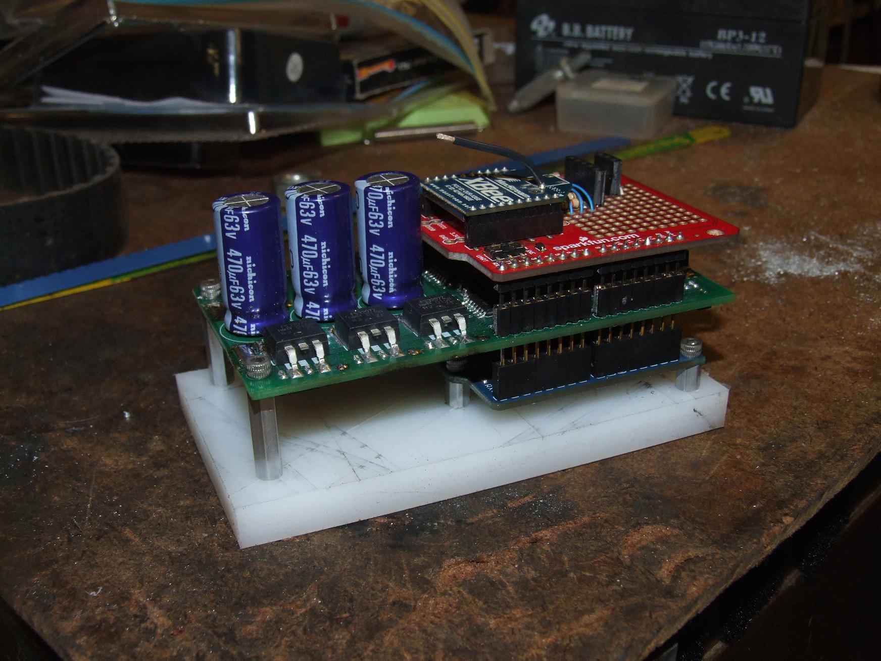
As described in its own post, the Hexbridge shield is an attempt at creating a system for Arduinos to control more power than they deserve to. With twelve total IRFB3207 FETs straight out of International Rectifier’s private corporate Hell, the board could process more than a kilowatt of power.
The six half bridges are nominally divided into two independent 3 phase bridges by the 2 PWM pins of the Arduino it occupies. Now, while one rail of IRFB3207s alone can probably handle the Melon motor with proper current control, the board itself has no current sensing provisions. I elected to activate the other 3 phase bridge and put it in parallel with the first for that extra burst current overhead, since I was aiming to just make a simple open loop BLDC commutator. The way to accomplish this is to disable one of the PWM pins completely (high-Z) and then tie the selector pins together in either software or hardware.
This mode is the “secret mode” of the Hexbridge, and comes with risks such as EPIC CROSS-PHASE SHOOT THROUGH if the paralleled phases are not in absolute sync with each other, such as if the selector pins aren’t ganged together properly.
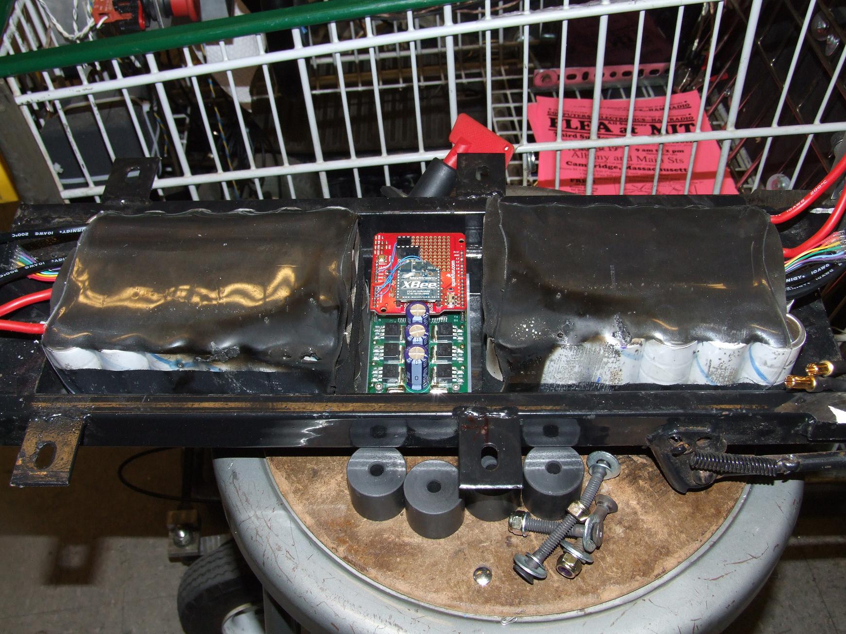
What was extra cool about the Hexbridge shield was the fact that it fit exactly between the two \m/etalpaxxx. Space efficiency!
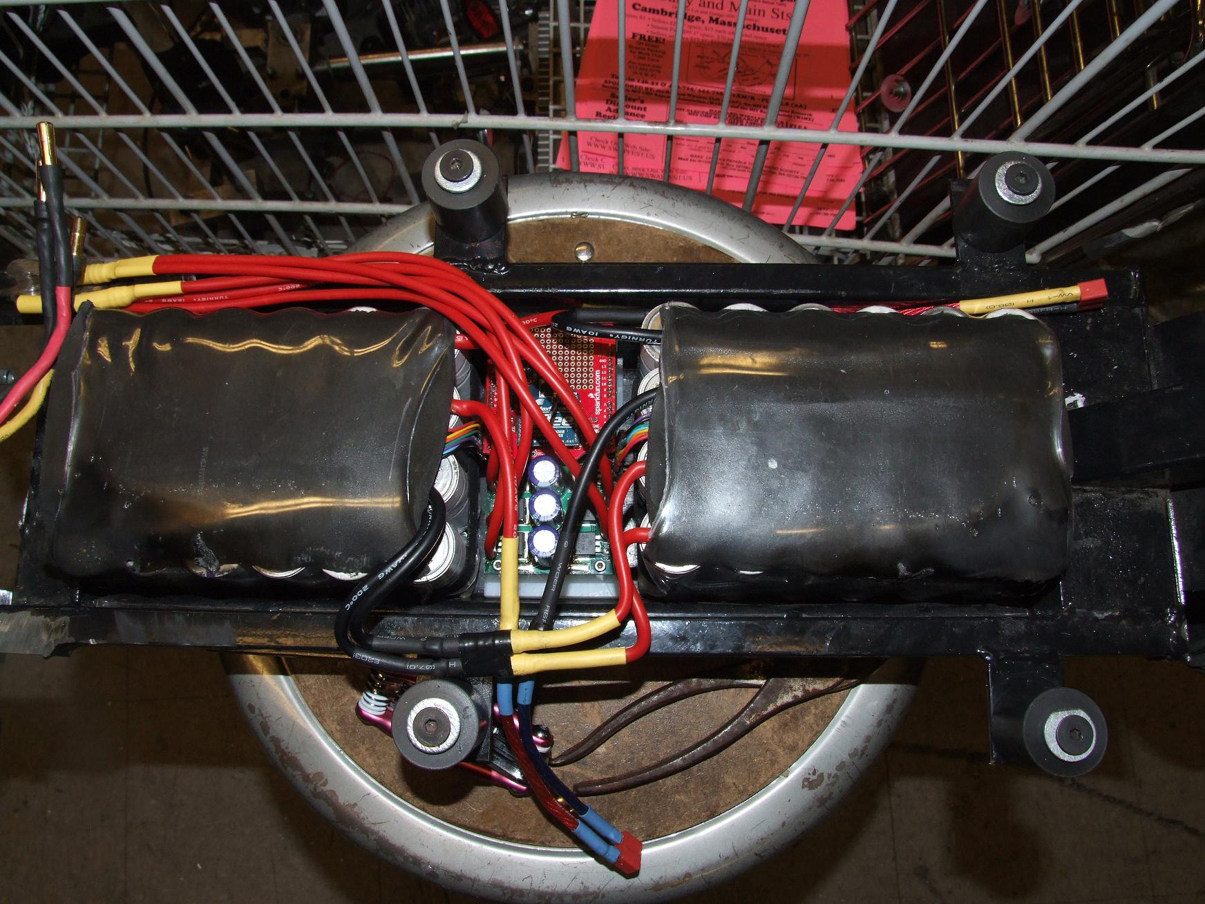
I yoinked a few feet of silicone wire from the Media Lab and hooked up the main power wiring for the system. As usual, with things I wire, it’s a mix of gauges, strands in parallel, and absurdism. Yes, that’s double 12 gauge coming out of the shield…. fed, of course by a single Deans connector at the other end.
Hey, I figure too much copper is not a bad thing from a system resistance perspective. In fact, the shady master key switch probably contributes more resistance to the system than anything else.
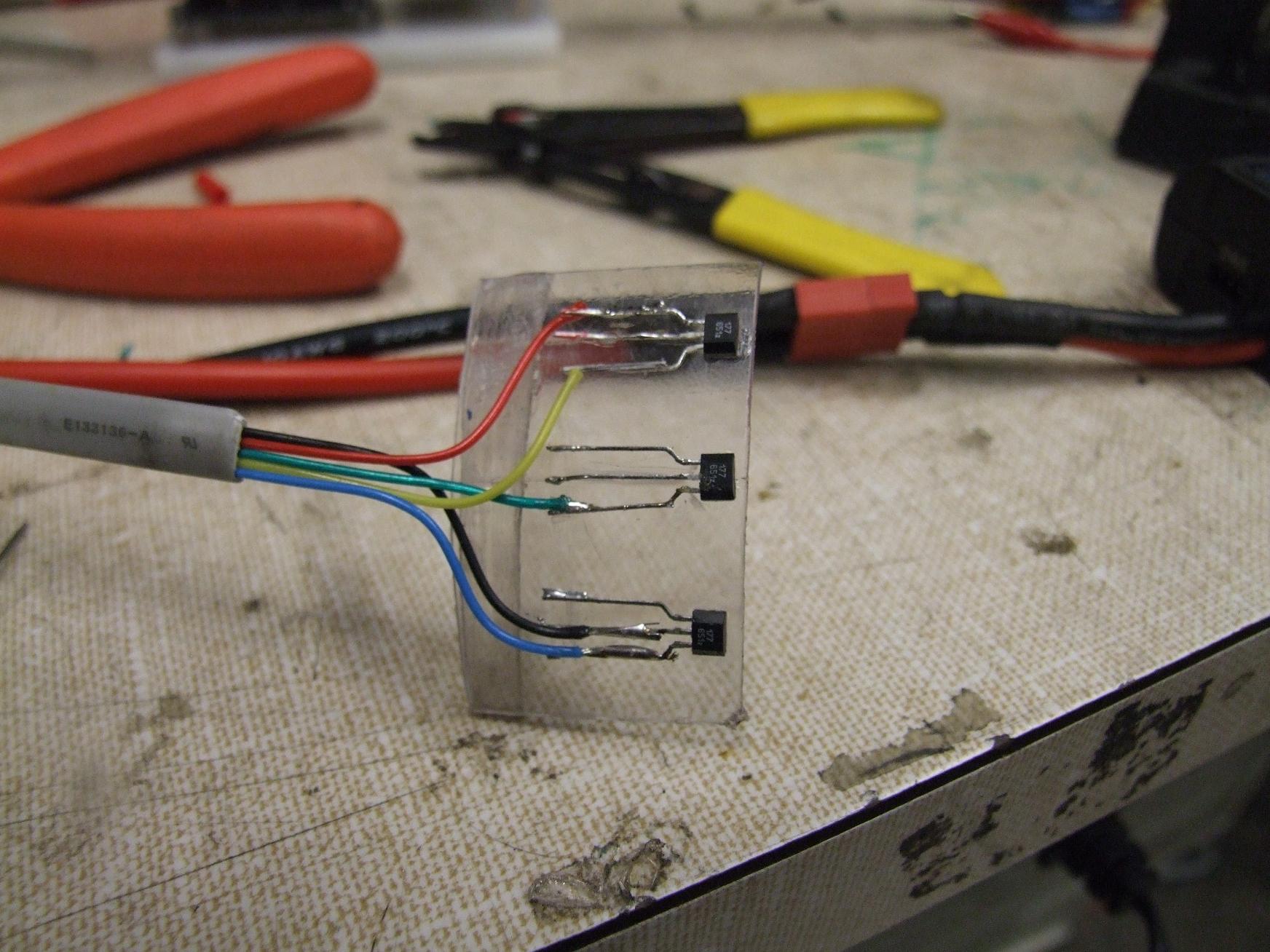
Because the motor does not come with sensors, I had to craft a sensor board out of some thin tube plastic. This is a departure from how I usually do sensors – which is stuffed inside the motor’s stator slots – because I didn’t particularly feel like taking apart a motor that big.
As such, I could take advantage of the fact that the sensors can be located physically close together to detect the proper magnet transitions. The formula for sensor spacing in degrees is 360°/P/3¹, where P is the number of pole pairs. So for the Melon, it was just 360 / 7 (since it’s a LRK wind) / 3, or about 17 degrees. Across a roughly linear projection, the sensors had to be about 0.48″ apart. This board was superglued to the exterior of the stationary motor mounting base.
The cheap hall sensors I used (p/n ATS177) exhibited some very weird behavior when I read the 3 lines out with the scope. One of them seemed to be “preloaded” and did not exhibit the 50/50 duty cycle I would have expected from a Hall sensor subject to a constant frequency alternating magnetic field composed of equally sized magnets. It meant that one motor state would overlap slightly with another, which at best could cause the motor to just not start (and at worst cause current spikes).
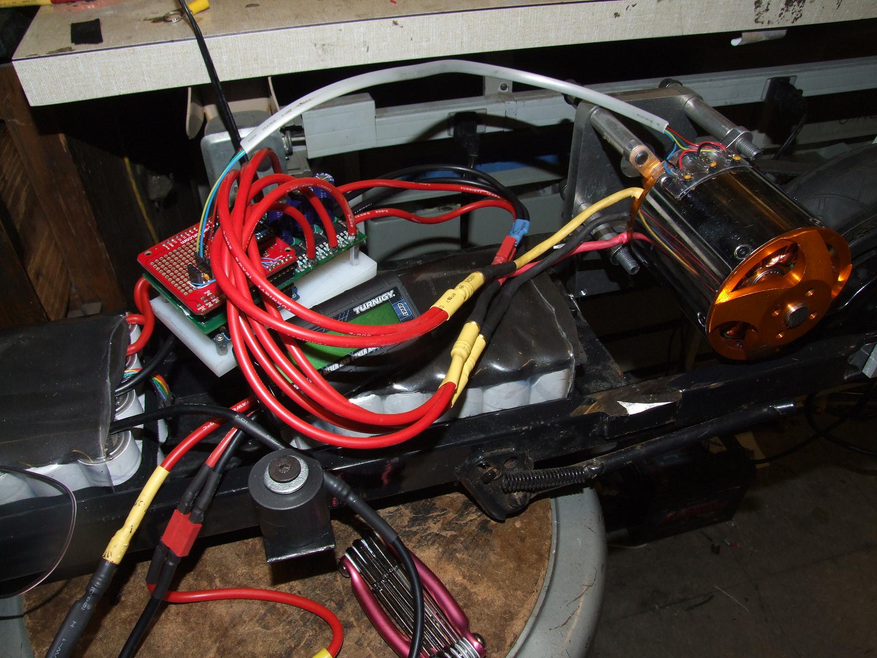
Here’s the basic wiring hooked up to do a commutation test. I loaded the same Hexbridge-and-Etek code on this assembly, making sure to lock out one PWM and hardwire the two PWM pins together before powering the system on and trying out the throttle. After digging through a handful of sensor:phase combinations, the motor finally started up. It was a little rocky sounding, but it did work.
Now, those of you who pay attention to words I put in bold and the subtle details of my sentence grammar will probably guess what happened.
After 7 seconds of operation, there was a large spark, and the power side of the Hexbridge was history.
The most plausible explanation, as it turned out, was that I neglected to tie the ABC selector pins to the UVW ones – in either hardware or software. I made them all high impedance instead, in software. So not only does that mean one half of the whole thing was never actually switching, the floating FETs themselves might have been subject to dv/dt-induced spurious turn-on.
Uncool.
mini-kelly
I was determined to get this thing running. Maybe too determined. After the Hexbridge exploded, I jumped to my backup plan of using a KBS series Kelly controller, of which we have aplenty in the Media Lab. At this point, I didn’t even care about monster horsepower. I just wanted it to move, because I wanted some transportation (that didn’t involve me actually doing physical work, I mean. Heaven forbid I use my legs to propel myself…)
Kelly controllers have a penchant for randomly exploding, but I must say this one did an admirable job given the adverse circumstances it had to tolerate. It’s a 20 amp rated controller with peak 50 amp ratings and here I am asking it to run a motor which will easily knock down 150 to 200 amps on a bad day.
It did an excellent job of keeping its own current so low that the scooter was able to move maybe 3 or 4 miles per hour, all the while sounding like a moped. The rockiness of the sensors really exhibited itself here.
In the end, nothing happened. I took the Kelly out of the system while it was still undamaged and useful to our Media Lab-y purposes.
oh, damn it all
Fuck it. I’m going back to sensorless.
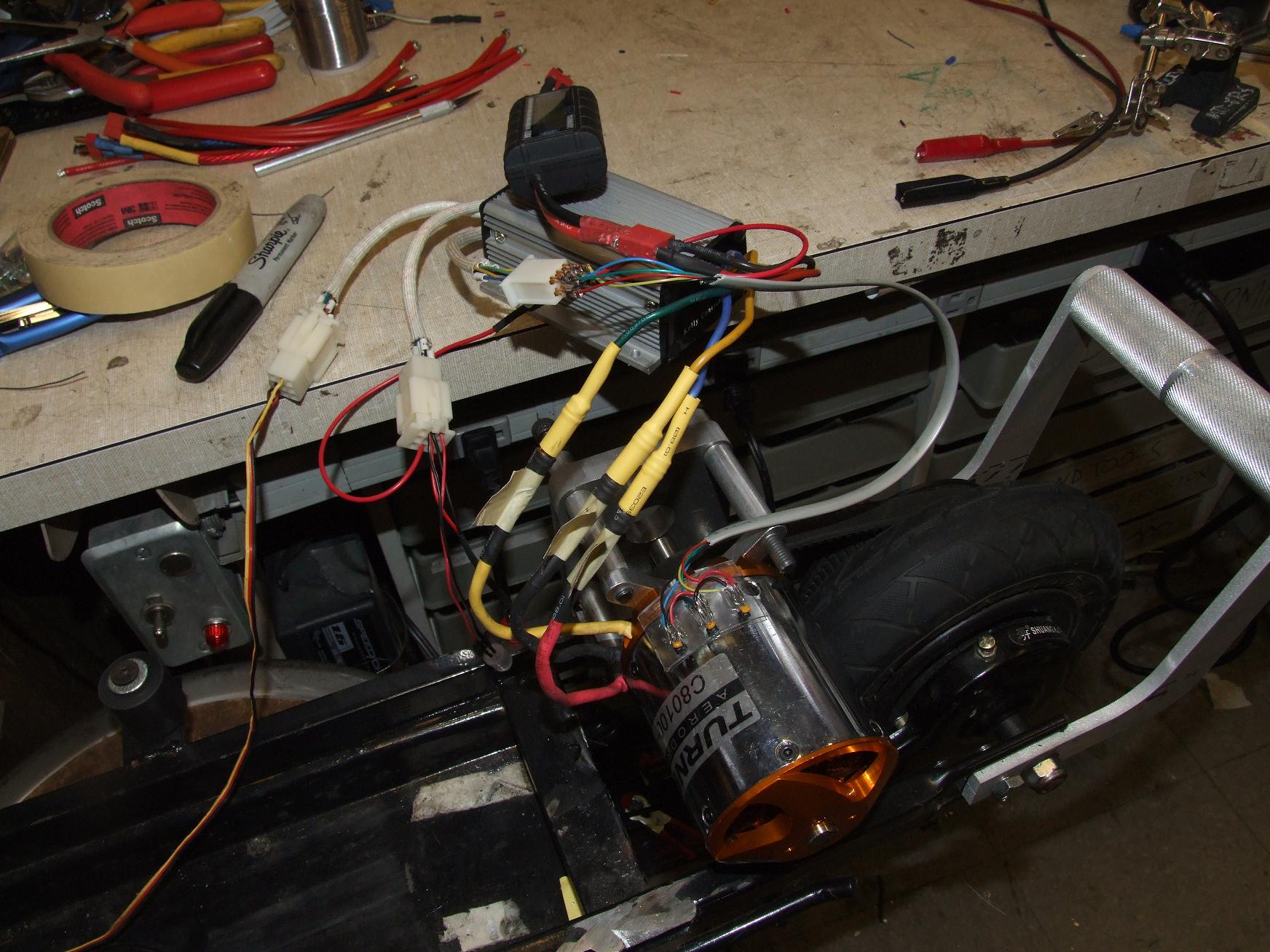
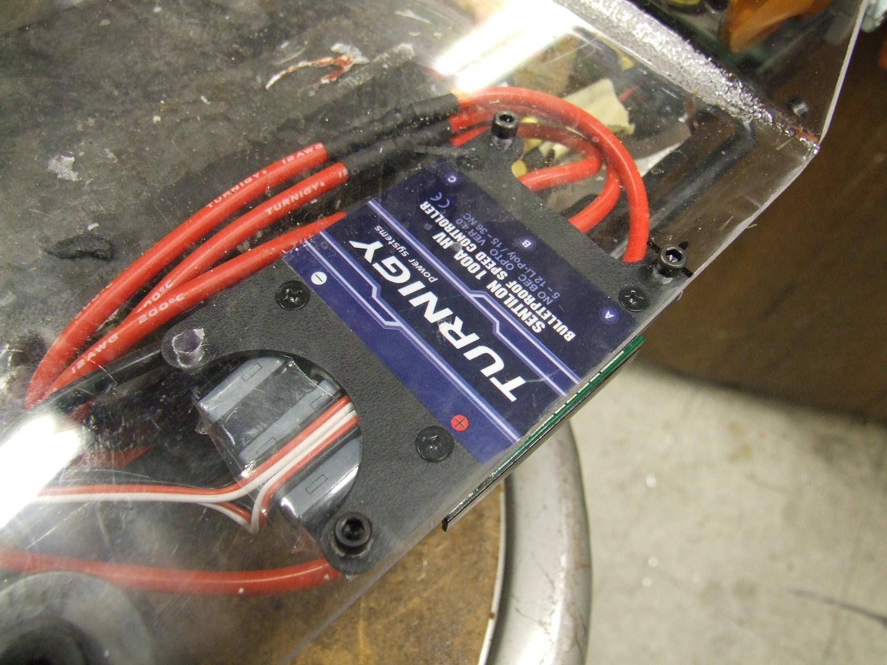
After a while of stewing, I bought a spare Turnigy 100A controller off Shane (thus funding some of the Pneu Scooter, which I look forward to) and threw it on there with the servo signal interface board.
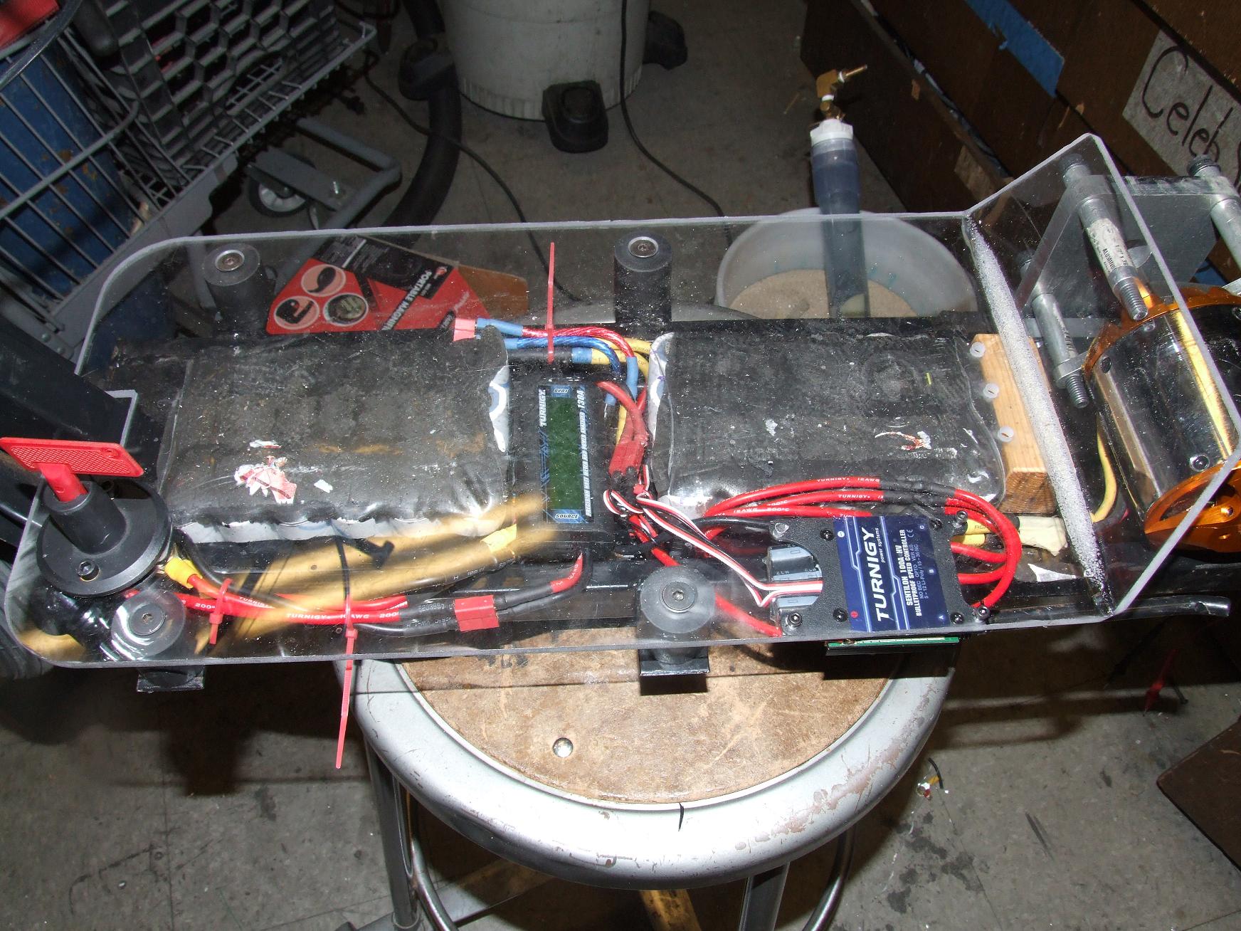
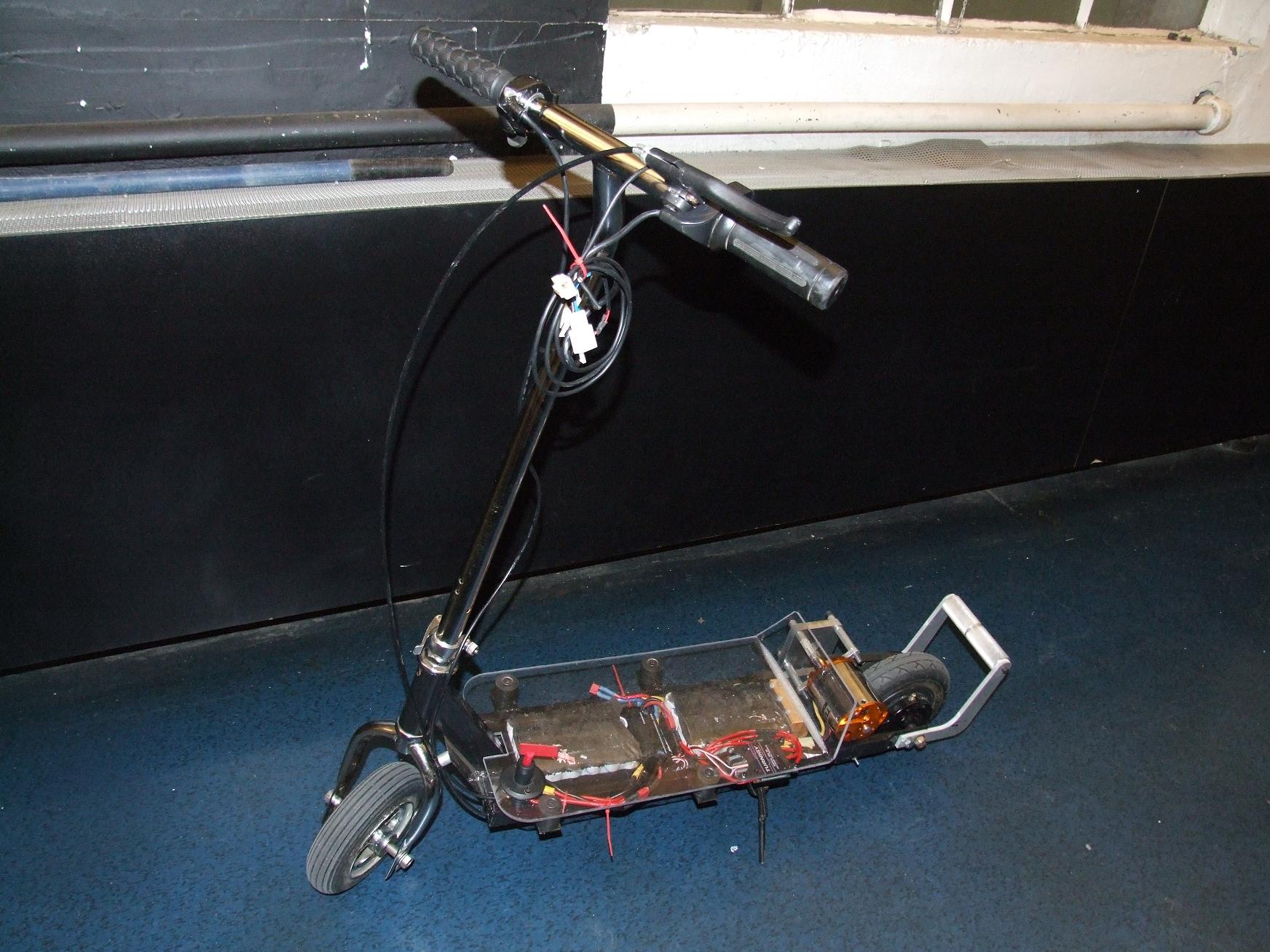
The new layout with the Turnigy ESC hanging awkwardly off to the side. Instead of stuffing it into the cavity, I elected to drill some mounting holes in the deck and put it in a path where it could get some real airflow, since heat is the killer of power-dense controllers like those.
The R/C meter tucks in between the batteries, and my secret ninja servo converter hides under that, waiting to strike.
And guess what? It works. It’s a power system I originally assembled in 2007, while still in high school. It’s nothing more sophisticated and would blow up the moment I floored the thing from a standstill (so I’m always careful on the throttle until the vehicle is already moving a few MPH). Hell, it even uses the exact same cheap R/C power meter (model-wise… not the physical same, mind you).
I said this thing was just a quick dumb-but-awesome build. It’s Fankart with powered wheels and the ability to navigate city streets. Maybe there will be some running video, but Melonscooter has become my staple commuter vehicle now.
melontroller
But I’m not stopping there.
Putting together such a system isn’t particularly contributory towards making myself a better engineer (or person). I haven’t laid out the board yet, but I am absolutely determined to tame the Melon. And I intend to do this by making a current-controlled BLDC motor driver board that
- will operate with a 48 volt electrical system
- at up to 50 real amps continuously and 150 to 200 amps peak (limited)
- have current sensing on the DC bus and two motor phases
- be fully regenerative
- be two stacked boards about the footprint of a common business card
- be modular, with one signal processing board and one brute force driving/current feedback board
- and possibly do crazy insane batshit things with motor control.
Oh, it’ll run on Arduino.
It’s a long shot, and will probably cause melonscooter to be the LOLrioKart of 2010-2011 (not that LOLrioKart isn’t already the LOLrioKart of 2010). But it will be the only component of Melonscooter that makes it a worthwhile project, so I’m going to go for it.
f
I hope you’re going to post the code!
Would love to see some examples of BLDC control for arduino…