No, this has absolutely nothing to do with Ke(§, Š, Σ, ∫…)ha, but it’s been more than a month since the last Deathblades update. Charles, where are my Deathblades?! Aren’t they supposed to be done by, like, last year?
I went through a flurry of work before the De Florez award judging in order to have one skate power unit on display. As we all know, that didn’t go too well, and I spent a short period of time afterward wallowing in self-pity, loathing all that Mechanical Engineering stood for, and recklessly experimenting with Course VI (you know, a harder substance). About the same time was when virtually all my carbide indexable lathe cutters were chipped or broken and the shop had exhausted its consumables, such as bandsaw blades and most importantly, sanding belts. So overall, there was very little incentive or motivation to work on the ‘blades during most of May, especially with LOLrioKart finally working well enough to hoon, and the Media Lab’s spring Sponsor Week in full swing.
Here’s some of the progress from the week of May 4th.

This is a Deathblade axle. You may revel in the disgusting surface finish.
It’s dimensionally acceptable, but I had to machine most of the diameters with chipped carbide indexable bits. I leave my set out for the populace of MITERS to use, but unfortunately not everyone knows the handling differences between HSS and carbide. About this time, I placed an order for new tips, but because of the whole transcontinental shipping issue, they would not arrive until the middle of May – so I pressed onwards.
The terrific finish is more apparent from this angle.
Those end threads were single-point cut with a threading tool. I’ve gotten decently fast at threading from making the motor cans, but I still need some technique improvement (and a non-dull threading bit, but that was coming in the order). I got into the habit of reversing the whole machine (disengaging the threading nut) such that by the time I’m back at the start of the thread and had finished making dimensional adjustments (returning the cross feed to my set zero and advancing the compount), it was nearly time to re-engage it and throw the machine back in forward.
A plan view of the Negative Volume of Wire Accessing. I’m using a slightly different technique than the scooter motors in that all the wires will come out the center of the shaft – not through a keyway or flat. This time, the axially drilled hole meets a radially-milled slot within the confines of the motor. It leaves plenty of room for termination and is a fast setup and operation.
The center hole is 3/8″ in diameter, and the slot width is also 3/8″.
Stator test fit!
One side effect of the material removed by the drill and slot is that the axle is somewhat springy at the center. When I press a stator on, that portion of the axle deforms slightly and preloads the fit.

Motors quasi-assembled and installed for a test fit. I ended up pressing the stator back off for the display item because that would have made assembly and disassembly more difficult with the magnets already installed.
The future electrical harness would exit the motor and immediately curve back towards the center cavity. For experimental purposes, I’ll probably just drill holes, run the wiring inside, and leave things permanently joined – but I could see a frame-mounted connector for any Legit™ versions.
![]()
As tools and accessories began arriving in late May, I was drawn back to Course II and briefly blitzed some more Deathblades work. I decided to go all out and use club funds to replace everything that had been consumed, broken, or otherwise rendered less useful – numbered drill bits, taps, endmills, fixturing utensils, etc. Oh, and of course a full set of replacements for the destroyed carbide tooling.
And one more thing….

It’s a knob on a stick!!
I got this die holder along with the tool shipment because as much as I love single-point threads, it’s slow and inefficient. Why do that when people already make tools to perform the whole operation all at once and better than you ever can?!
The holder accepts dies up to 1.5″ round, which covers most thread sizes that I feel like making. It has a 3/4″ hollow shank that has a roughly 9/16″ through bore.
Problem: I only have a 1/2″ drill chuck.
So the first thing I made with the new shiny (and sharp) inserts is a medium carbon steel roughly-9/16″-to-1/2″ adaptor shaft. I then split the shank on the die holder, shoved the adaptor into the through-bore, and put a 3/4″ shaft collar over the whole thing.
It was like a useful version of Überclocker’s first fork drive.

Here it is, mounted in the tailstock chuck of the Old Mercedes, and holding a 1/2″-20 thread die like only a die holder can.

To use it, I put the spindle in the lowest speed setting, dunk the part in threadcutting oil, and let the tailstock pull itself along by the threading action.
Well, it works as advertised, I suppose?
With the die holder, I decided to finish the rest of the motor shafts. And with the NEW!!! SHINY!!! SHARP!!! indexable tooling, I cranked out the last two motor cans and their associated end plates. Notice how much SHINIER the front two cans are? Did I mention that they’re SHINY?
The frame plates I cut out for the other skate frame were just kind of sitting there and being lame, with me having no abrasive tools to perform the Zn-Al brazing correctly. After deciding that I was groveling too much and needing to make progress, I made a private Enco order for a stack of sanding belts and a McMaster order for small wire brushes.

Here’s the result after a few minutes of hitting the aluminum plates with the aforementioned sanding belts. I didn’t really go into detail last time about how the frame actually went together, or posted a picture that wasn’t the frames fully assembled.
As can be observed, I pile all the medial plates on top of a side plate before slamming the other side plate on top of the whole thing. All the tab edges have been sander-chamfered for better acceptance of the brazing alloy.
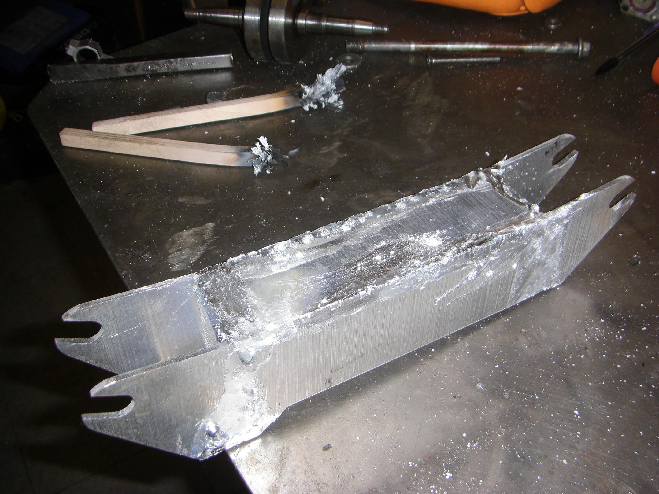
This globbing phase went substantially better because of the pre-sanding, which meant less oxide to strip, and the fact that I used the propane torch wide open. I now realize the reason that Cold Arbor took so long is due to me going easy on the torch and the heat. Nope… tons of heat, add tons of alloy, and brush like molten metal is going to set if you stop brushing.
… which is not exactly far from the truth. The two casualties of this intense brushing can be seen behind the frame. Wooden brushes do not appreciate being vigorously used in the path of a propane torch flame. Just for future reference, this tends to happen to them:

I am now glad that McMaster sells these things in 12-packs. It’s also kind of a pity that nobody seems to make or sell a metal version for under, say, $8 each. I think that I’d go through those just as quickly because the fine stainless steel lacing just burns away.
So for the price, I might as well burn through $1.20 wooden ones.

After attacking the globbed frame with 60-grit high-speed sandpaper, the second frame emerges!

Alright, it’s hardware poser picture time!
Completed:
- 4 motors cans
- 4 fixed endcaps
- 4 removable endcaps
- 4 center axles
- 4 cored out wheels (couldn’t find two matching sets by color…)
- 4 wheel retaining collars
- 4 stators removed from their respective copier motors
- 2 frames
what’s next
I ordered a set of 6S (22.2v), 2.6Ah lithium polymer packs three weeks ago, but they have been delayed due to international shipping regulation changes regarding lithium batteries – so here’s your cue to stock up on Li cells before they are regulated out of the reach of hobbyists and amateurs, like most cool things. I predict this will happen within 5 years.
Along with the lithium battery order were wiring connectors and minor electronics, which I’m not exactly hurting for.
Despite stating before that I didn’t want each skate motor to be high powered, I decided to run a high system voltage anyway due to the available of the DEC Modules. Stator for stator, a higher voltage, lower current motor generally produces more torque than a low-voltage, high current motor. This just means I will probably wind the skate motors with many turns of finer wire to get a torque constant on the order of RazEr’s motor, 0.25 Nm/A.
It’s time to start laying out the electronics. Each skate will have a signal board that carries two DEC modules and an Xbee radio, sitting on top of the battery (which takes up 80% of the internal volume now). I’m debating designing a board (committing myself to an electrical layout before testing the whole rig on the bench) or just winging it again with protoboards and hardwiring…
Oh, yeah, I also need to perform the mundane task of WINDING ALL FOUR MOTORS. Not really, because I only have the magnets for two – so maybe I should place that order soon!
deploy plan
Currently, Deathblades has (have?) no planned deploy date – I’d like to get them done before summer’s over. However, going back to its anime roots, it might premier at Otakon, which I plan to attend with a contingency.
I’d feel horrible if I costumed as an Air Gear character, however, since I was only able to stand about 3 episodes of the thing.
/Cheer!
Woot an update :) You are steaming along nicely on the ‘blades. No need to wallow in self-pity about that contest thingy. I am glad you got your hands on some new tools, they really make building funnerer.
I have a question, when designing a motor, how does one decide how large/number of magnets should be in relation to the size/number of the poles on the laminate? Am I thinking about this all wrong? I am sure there is some fairly simple logic to follow I have never felt the urge to scratch build a motor, but you have me curious about trying one now. I could rely solely on Google but you have hands on experience :)
Years ago I would rewind my rc motors, using a prop balancer to balance them lol, they worked, for a few runs, until the bearings gave up the ghost. I remember making a 6 turn single that fried my speed control wide open, and after running the length of the parking lot which was about 60 yards, rapidly re-kitted itself on a curb. It was awesome :)
Keep up the cool projects!
Patrick
Have you read through http://www.instructables.com/id/Make-Your-Own-Miniature-Electric-Hub-Motor/ ?
Thanks for the fast response. I have to admit that Instructables ticked me off pretty bad and I was avoiding the place. I took issue with their definition of “Pro” It was the last place I would have thought to look.
I really should /facepalm some more, I just realized I have seen this link on your site before. Doh. Mebbe I just need some Dew?
Thanks