A long time ago, I drew up a concept bot for NK5.0, but never got far with it. After MIT hit, I found myself focused less on the robots and more on… well, MIT. Now that summer and its associated nonproductivity is approaching, I have redone the bot in full, just like Pop Quiz. Lots of changes have been made which reflects what I learned over the year and what tools I have access to.
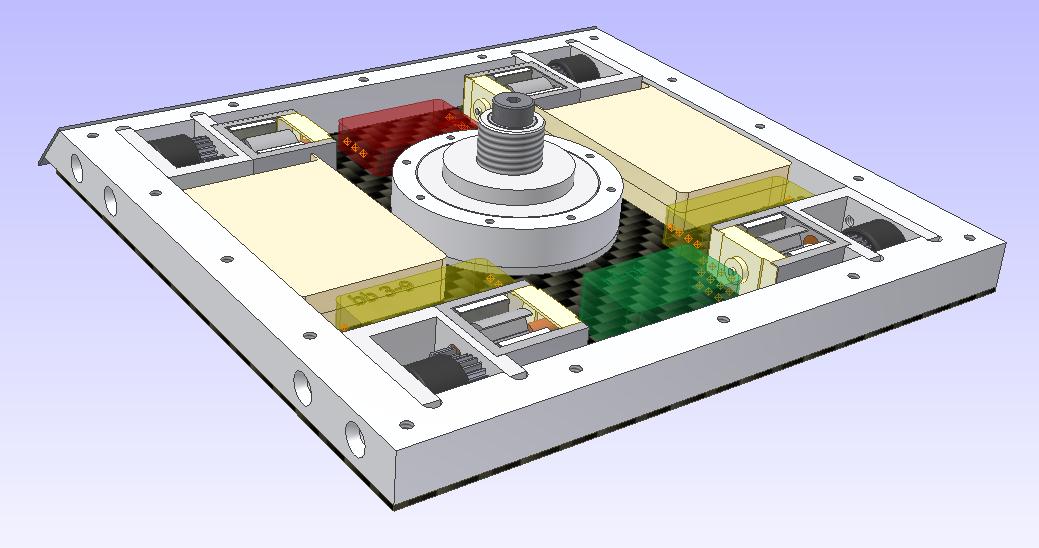
This is the old concept bot from July ’07.

It’s a radical departure from the current NK design. The most obvious feature is the large swinging weapon pod in the middle of the bot. This solves the invertability problem that NK has suffered from since the design inception. The drivetrain is symmetrical, and of similar layout to the current bot. It also uses the motor-in-disc design that I have been wanting to try.
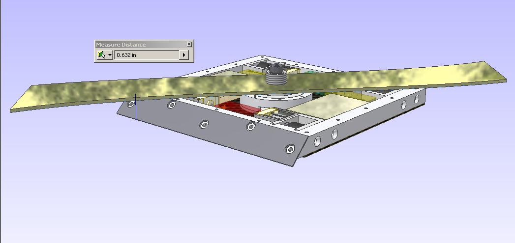
There are several problems with this design. The chassis has too many parts, and rather poor support in the back. The weapon pod is very thick and large, and the disc motor itself is extremely “overbuilt”. The bot in this picture weighs 2.6 pounds without any internals, hardware, or covers. It’s not going to make weight.
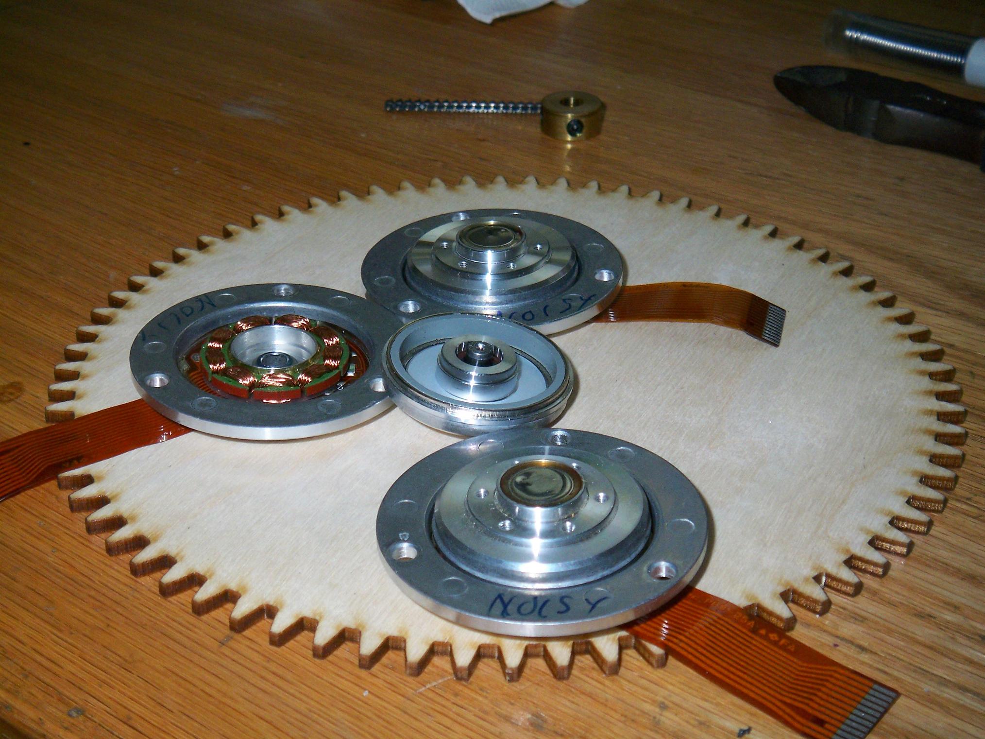
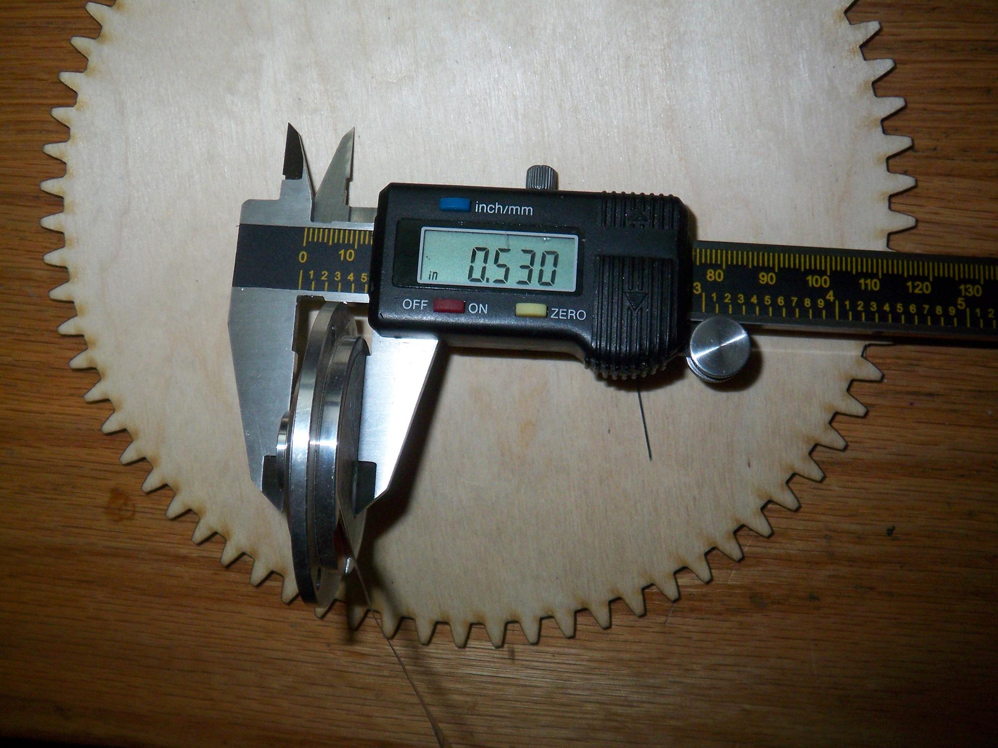
Also, the “fully integrated” motor-disc design was going to be impossible to pull off. No technology that I have easy access to was going to cut those inside “rutts of magnet holding” on the blade bore. Wire EDM could manage it, but I don’t have access to such a thing. A waterjet would be too messy for the tolerances required.
So I set out over the week to redesign the bot so that it can actually be built.
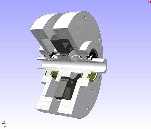
I found a convenient button on the Inventor toolbar that allowed a section view of the assembly. So here’s a cross-section of the old discmotor design. It’s about 1.25″ wide at the rim, and 2″ wide at the shaft, with massive 12mm bearings. The stator is also mounted using a real bona-fide hub using its bolt holes, and the wires exit through the hollow in the shaft. It weighs more than half a pound alone, and there are some material properties I forgot to set (and Inventor will not let me reset to find out…)
I threw this out. It’s simply too overbuilt, but would make a nice dual-blade setup for a bigger bot, one per side.
This is the new motor design.

It’s one inch wide at the shaft, and weighs about 6 ounces. In essence, it’s a scaled down version of the scooter wheelmotor. This is quite reasonable when you think about it, since I could strap a big pointy thing to the wheelmotor and have it be a great weapon.
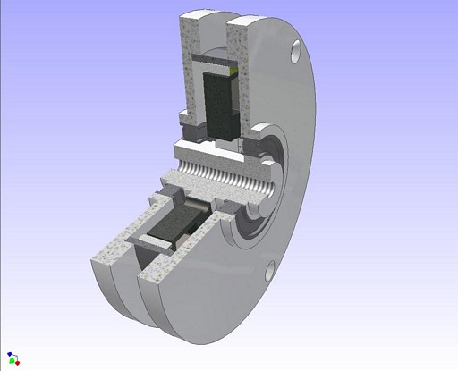
Here’s the cross section of the new motor. Major differences include a real motor can, sandwiched betwen the side plates, just like the wheelmotor. The stator hub was removed and replaced with a one-piece shafthub assembly which presses into the stator. I decided that in this size of motor it wasn’t worth giving the stator a bolted-down hub. Hell, the wheelmotor has a press-fit-and-Loctite hub. Another major difference is that the wires exit through an open space between a flat in the shaft and the bearing inner race. The bearings are larger in diameter, but narrower in profile and thinner radially. They are the same bearings used in the wheelmotor – I figure that if it can handle bunnyhops off sidewalk curbs and constant banging on cobblestone surfaces, a 3lber shouldn’t be much worse.
Overall, the construction is simpler and material isn’t overused. The motor is made modular and not integrated into the disc.

The whole discmotor. I eliminated the many large holes in the previous blade in favor of only three smaller ones. The hub area of the other blade design had huge stress risers in the form of large bolt holes in the inner ring. This has been replaced by three spoke-area holes, each much smaller. The main means of power transmission will be the clamping pressure from these three screws holding the side plates together as well as the screws themselves acting as shear pins.
Here’s hoping they don’t actually shear. The motor doesn’t have nearly as much inertia as the blade, so I’m not too concerned.

Next was chassis and drivetrain design. I wanted to retain the layout of the drive motors as well as 4 wheel drive. The back “legs” of NK have been shortened, and I might even eliminate them entirely (such that the rear wheels are within the rectangle defined by the main body. One big change is that the shortening of the legs allowed me to make the whole back end from one piece of metal. No funky bolt holes to line up, less pieces to cut and make.
The front and rear of this design are angled at 75 degrees. Although this is far less than the 45 degree slope of the current NK, I don’t think it will be an issue since NK shouldn’t be pushing anyway… Overall, the design is more compact because of the straighter sides.

Mostly done. I redesigned the weapon cage also, to make more effective use of less material. The weapon is set further back in the body to increase handling (The further out a big weapon is from the rotational axis of the bot, the harder it is to swing it around. The cage was reduced to 1/8″ aluminum (or titanium!) that is bolted together with standoffs at the ends as well as solidly attached to the motor. This is much more stable than simply attaching the whole thing by the shaft of the motor. The “feelers” on the end are taller in profile for more stiffness.

Closed up. The new look for 2008 and 2009 is carbon fiber and raw metal. I’ll be moving away from UHMW for primary external structure use because it is simply not durable enough. UHMW is great for absorbing shocks and flaking off on blade impacts (as TB demonstrated handily) but I don’t feel like rebuilding the frame every time.
There are a few quirks that you might notice. First, the bot’s asymmetrical when inverted. I don’t consider this an issue as long as it can move and I can wing it into something and flip it back over. And second, the blade is optimized for spinning upwards and would suck running the other way. This is, of course, something that can be easily solved by designing a bidirectional blade. Overall, movement is more critical when the bot is inverted.
Prospective parts for this bot include a 1200 to 1400mAh, 3S lithium battery (which ALL seem to be out of stock at United Hobbies), and the retainment of the Barello ANT150 which has served all versions of NK since 2.0! I also intend to keep the modified 25mm gearboxes that give the bot incredible speed and maneuverability for a weapon platform (NK’s top speed is around four feet per second). The gearboxes themselves are well-trashed and I will get replacements, but the motors are an odd size (Mabuchi 370 frame, commonly called “speed 300” by the R/C world) and I have yet to find them cheap and surplus, only retail for $8 per motor.

When you have multiple bots of a generation designed…
This is an overview of what the insect fleet will be, hopefully by the time Robot Battles and Dragon Con rolls around.
Let’s see if I can actually afford these build these!
Bot on.