The calm before the storm has begun.
After two weeks of hosing, I now have a week of reprieve before the wall of finals hits… hopefully not too hard.
So naturally I’ll take the opportunity to catch up on two weeks of building. First off is Pop Quiz, which I actually have a fair percentage of the parts for.
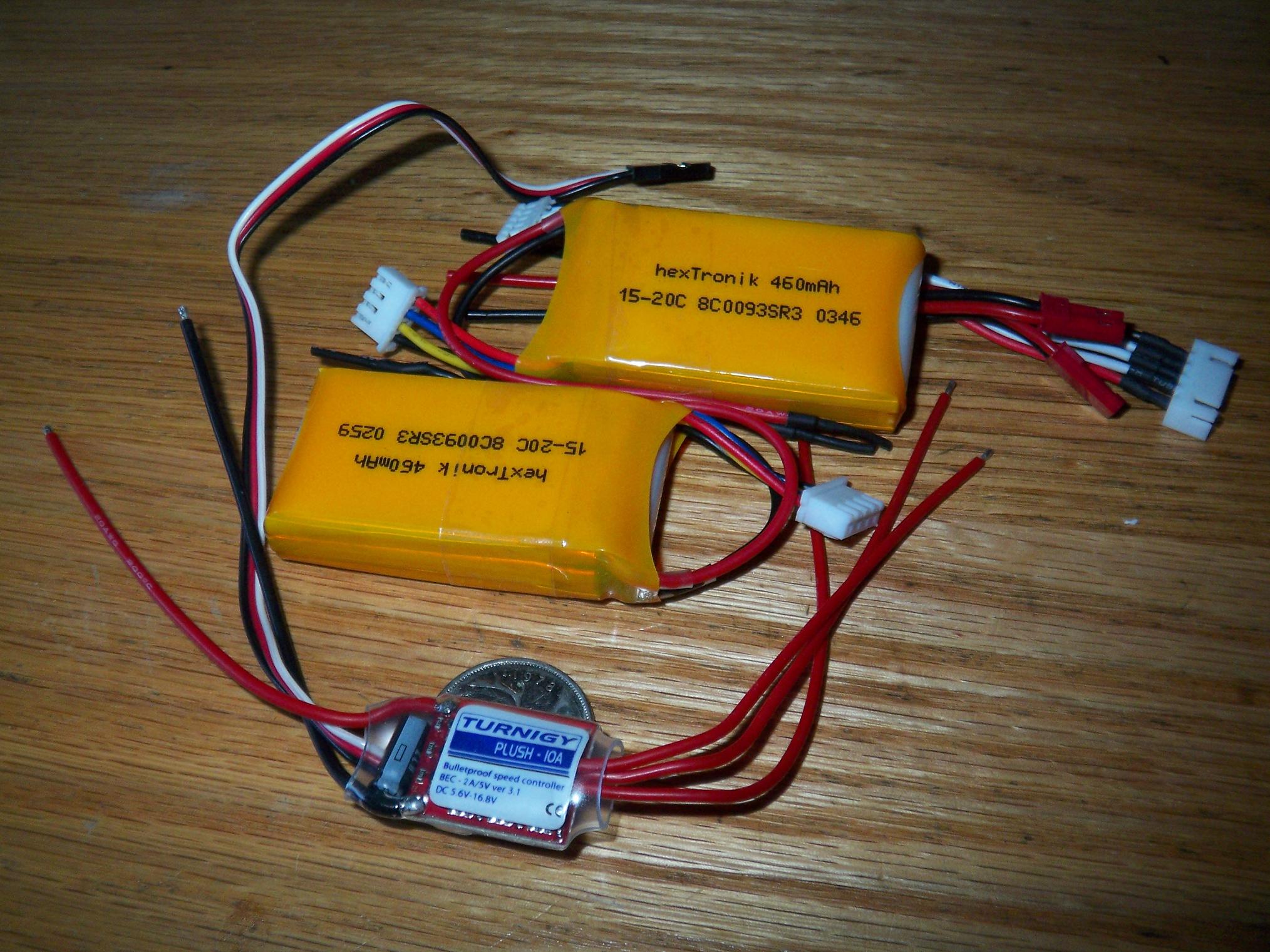
From United Hobbies are the replacement internal parts. After some idea juggling, I settled on some 460mAh packs rated for 15C discharge. This of course gets me an incredible 6 amps of maximum current, but given my intention to run everything in the bot mildly, should not get in the way.
These packs are 3S each, and I will remove one cell from each pack, then series the remaining to yield 4S x 460mAh.
The new 10A controller is unbelievably small – MUCH smaller than Pop Quiz’s current 10A controller by far. It has one SO-8 FET per leg of the motor driver bridge.
Still missing is the micro-receiver and drive ESCs. These parts are contingent on whether or not I can shove the old ones into the new design.
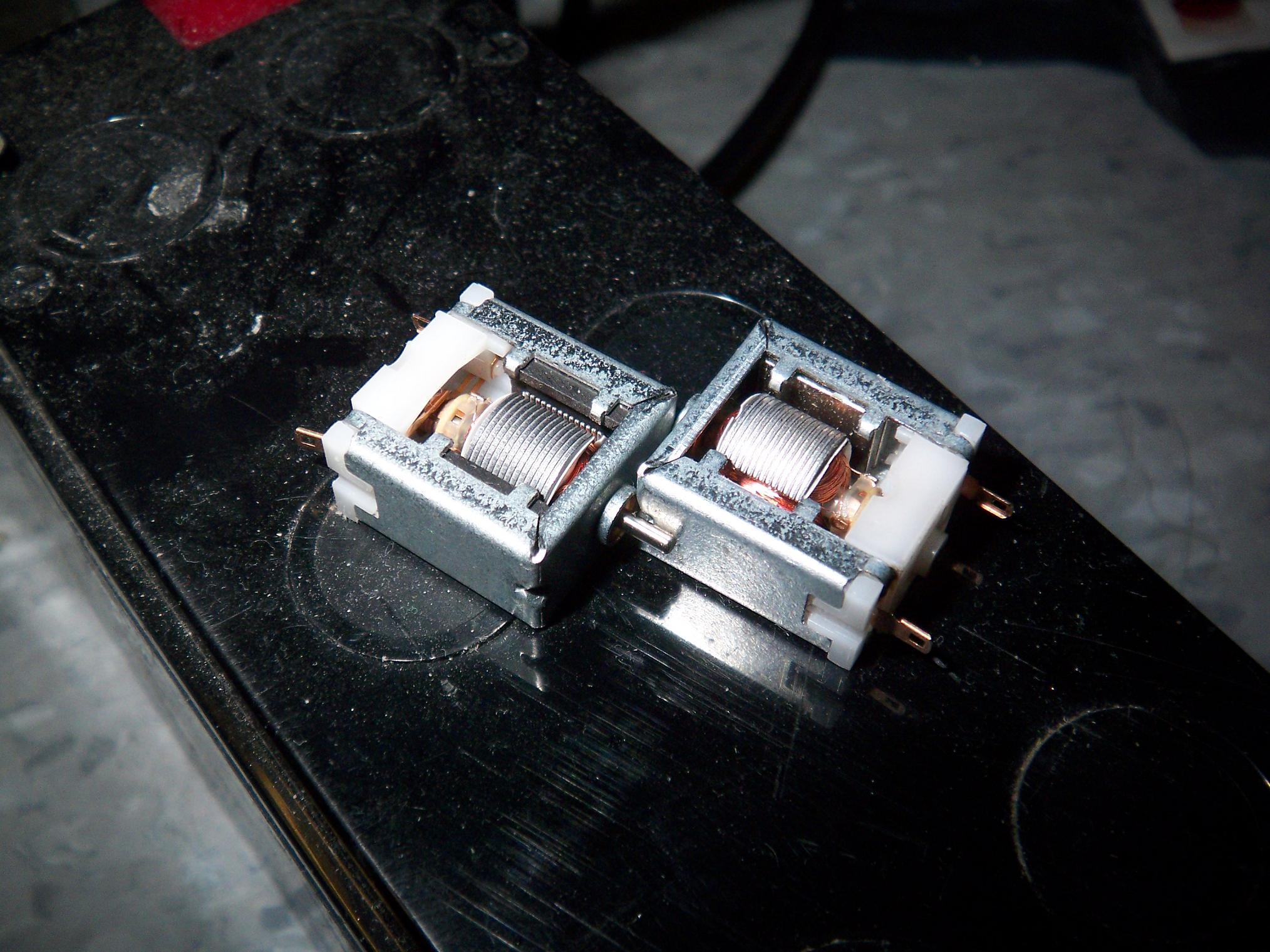
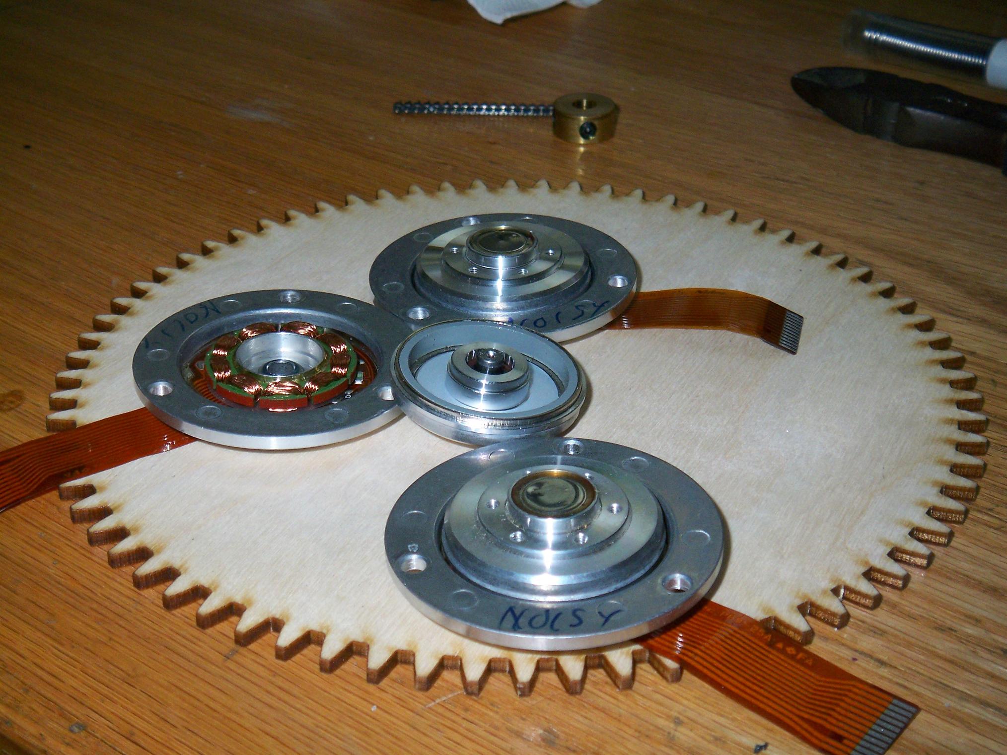
PQ2 drive motors! This is a side-by-side comparison of the stock Mabuchi slot car motor, and the neodymium-tuned one next to it (On the right). The “freewheeling noise” of the “enhanced” motor is substantially lower. According to my R/C meter, it draws an obnoxious .4 amps no-load, but oddly enough, runs smoother and with significantly less brush arc than the stocker. I wish I had some real equipment such that I can collect real data instead of jamming my finger into the rotor to see how easily it stops (Alot harder to stop the new motor, by the way!)
SDP-SI is out of stock on the exact size gear I need to fit the new drivetrain. Go figure – I’ll keep bugging them until they are restocked.
With those little details on hold, it was time to work on the new motor.
…but alas, disaster strikes even before starting.
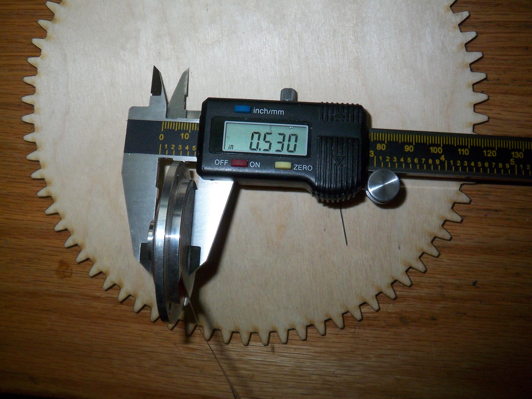
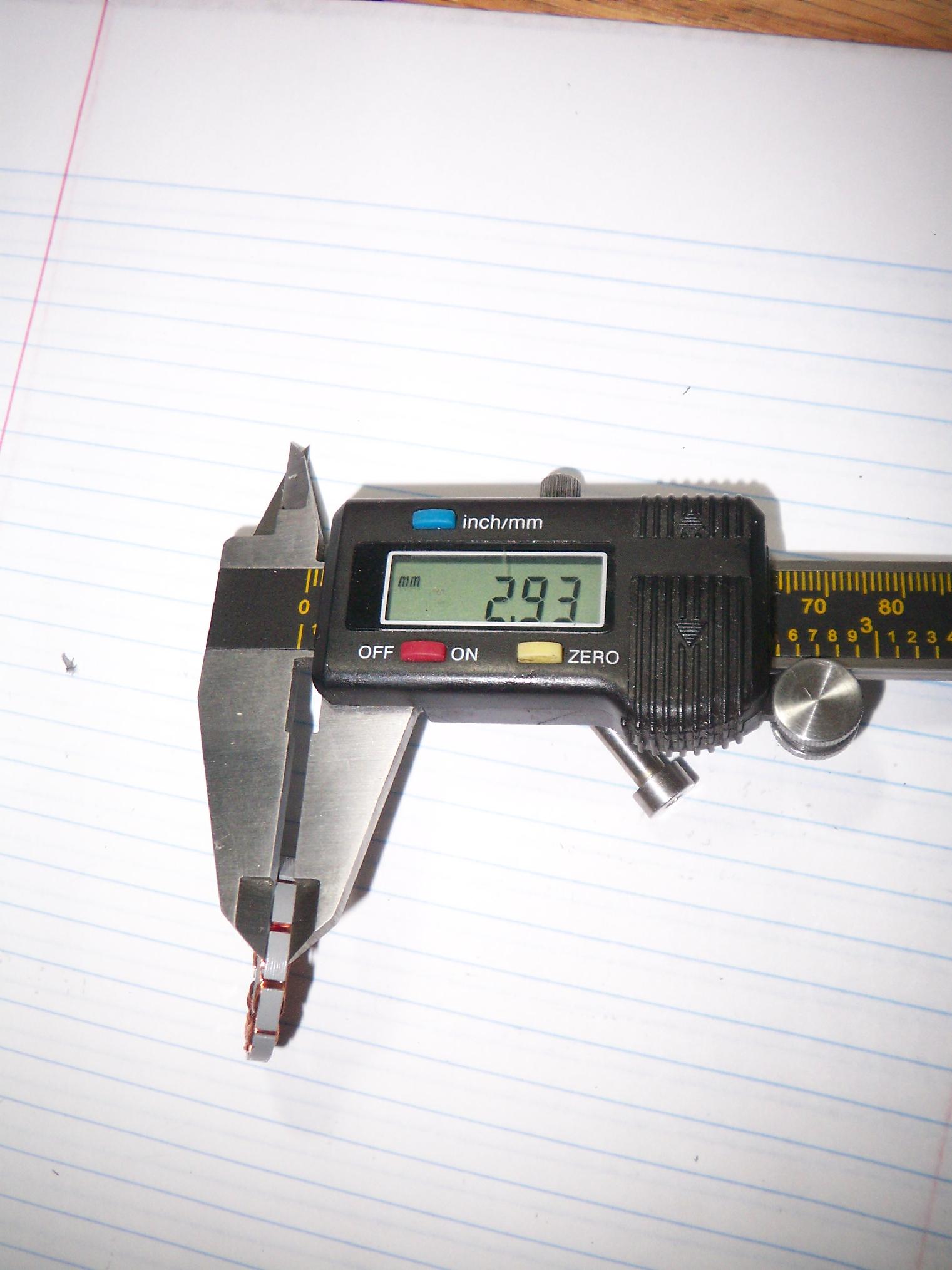
After popping the stators out of the motors I intended for the bot, I discovered they are in fact 3mm thick, not 4mm like I had visually inspected (Note that these aren’t the “flat motors” from the last update, but rather some HDD motors I had bought in 2006)
This was quite bad, as I had sized the design for a 4mm tall stator. This isn’t to say 3mm won’t work, since small fits in place of large, but would cost me some power as well as style points.
What ensued was a night of terror levied upon a box of old hard drives sitting around MITERS. I went through one of every unique make to see if they had usable spindle motors. There were only 4 brands and models in total – the rest were duplicates.
(MITERS obtained this after some server cluster on campus dumped their old hardware)
I hate new stuff. I really do. Because they ALL LOOK AND FUNCTION ALIKE on the inside. Not a single 4mm, 12 pole motor was found out of four drives. The only 4mm stator was 9-poled and 20mm in outer diameter, totally unworkable. Of course, going through more was only going to be redundant, so I called it a night and just worked on the motor frame itself.
I have some older (1990s) hard drives hiding under my bed that might prove more useful. Old things tend to have bigger motors. Or I could just harvest some plates from one stator and transfer them over.
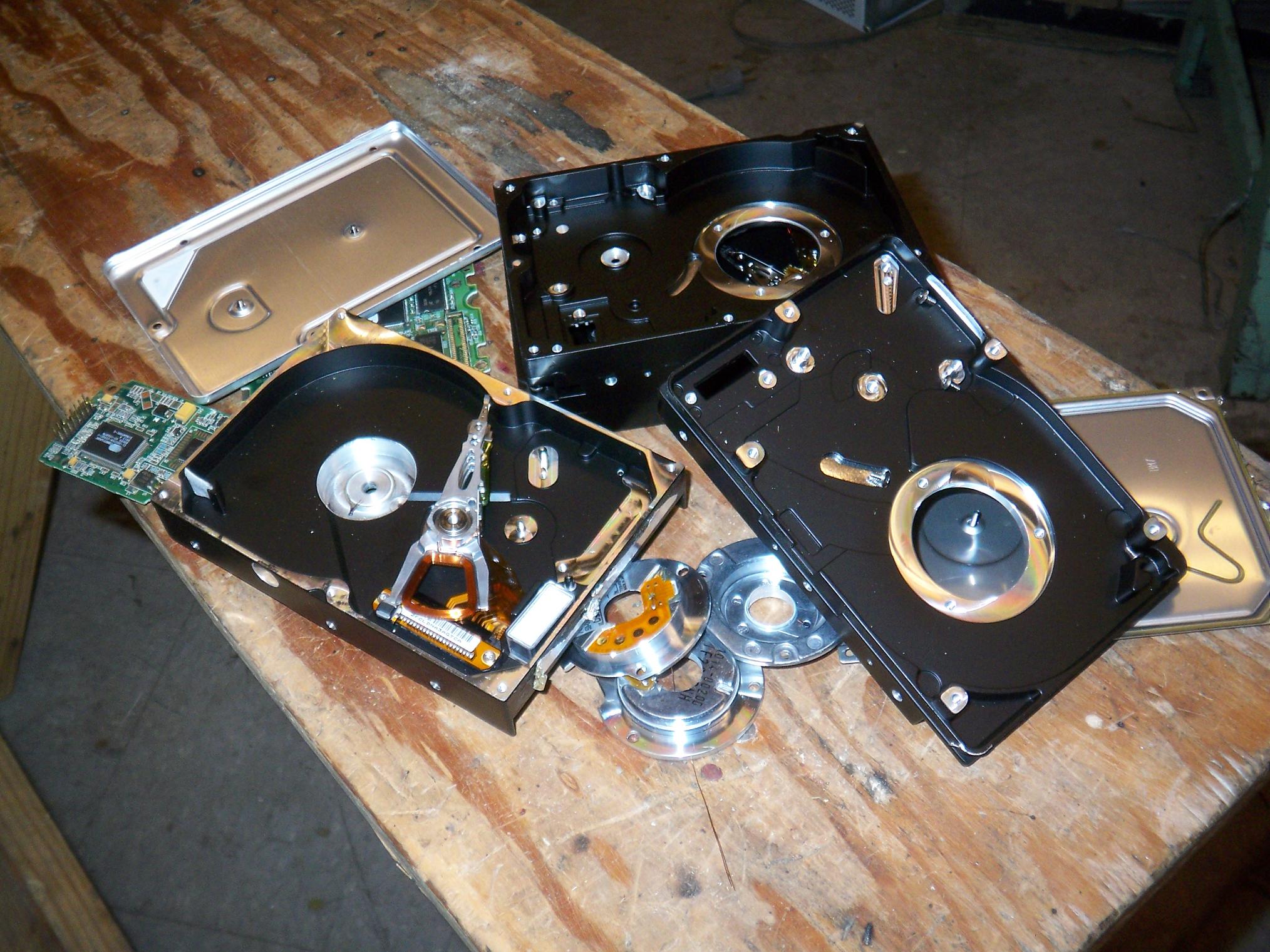
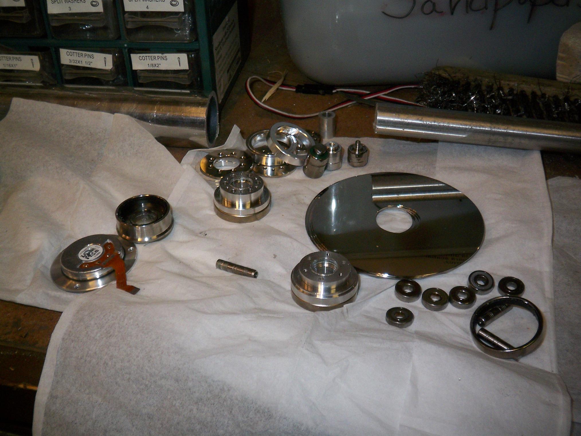
Result of the Night of Terror. The other MITERers were, of course, glad to act as parts vultures, stripping the discs, magnets, RW heads, and various random bearings and spacers. I wonder how many cents I can get if I recycle the casings.
Time to get down to business. Behold, the sketchiest sawing setup that has ever existed.
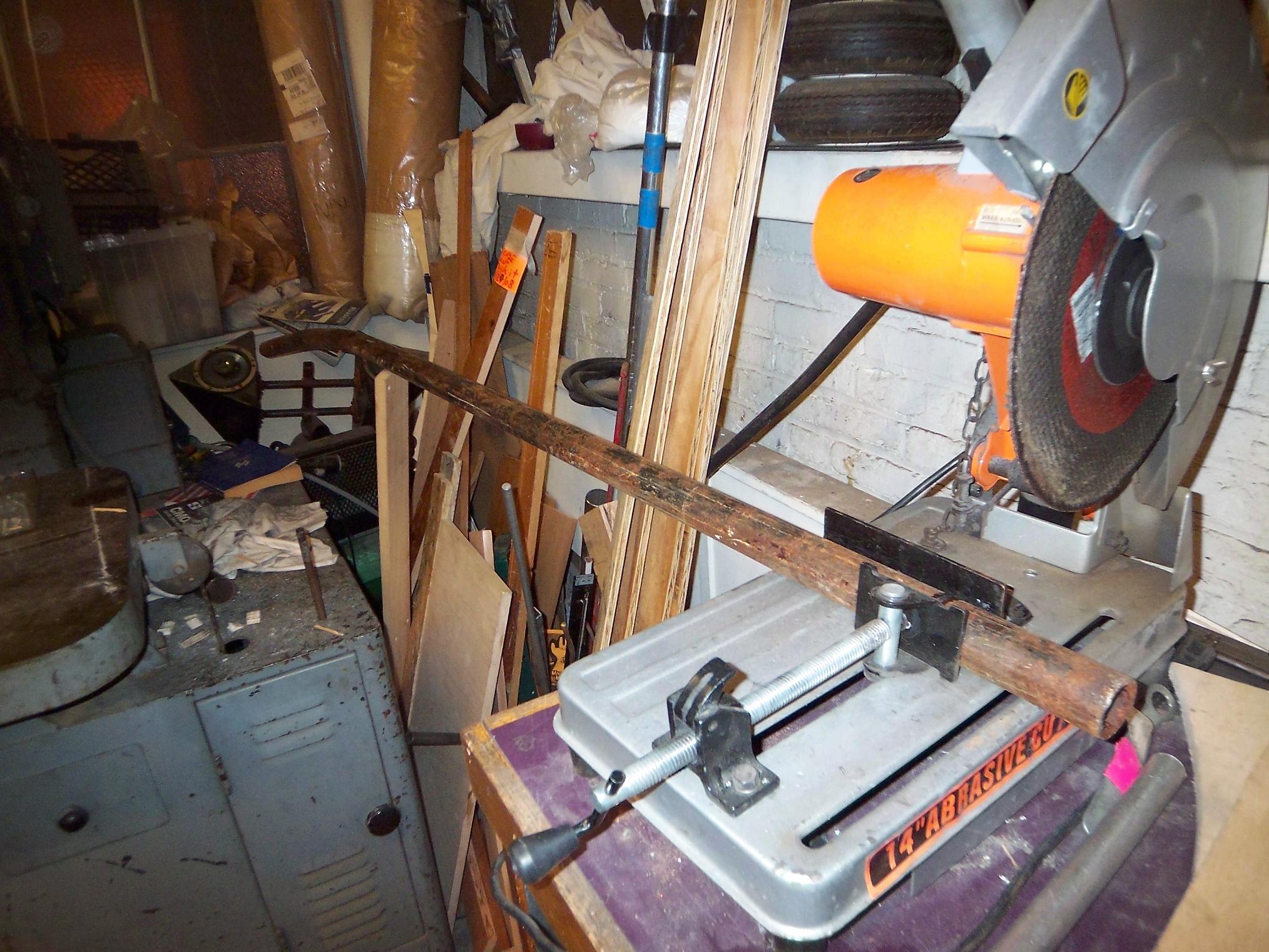
I needed a chunk off this 8 foot long, 1.6″ diameter steel pipe. There wasn’t really an easy way to handle it besides propping it up on the work table and using the abrasive saw.
Problem was, there wasn’t really a sawhorse or structure that could easily fit in the space provided. The solution was to prop it up with a wooden board and just hope nothing moves.
Nothing moved, but the effort proved fruitless as the inside of the steel pipe, when cleaned of rust, was around 1.3″ diameter. I need a 1.295″ ID on the magnet ring, and would rather trim outwards from a smaller pipe.
D’oh.
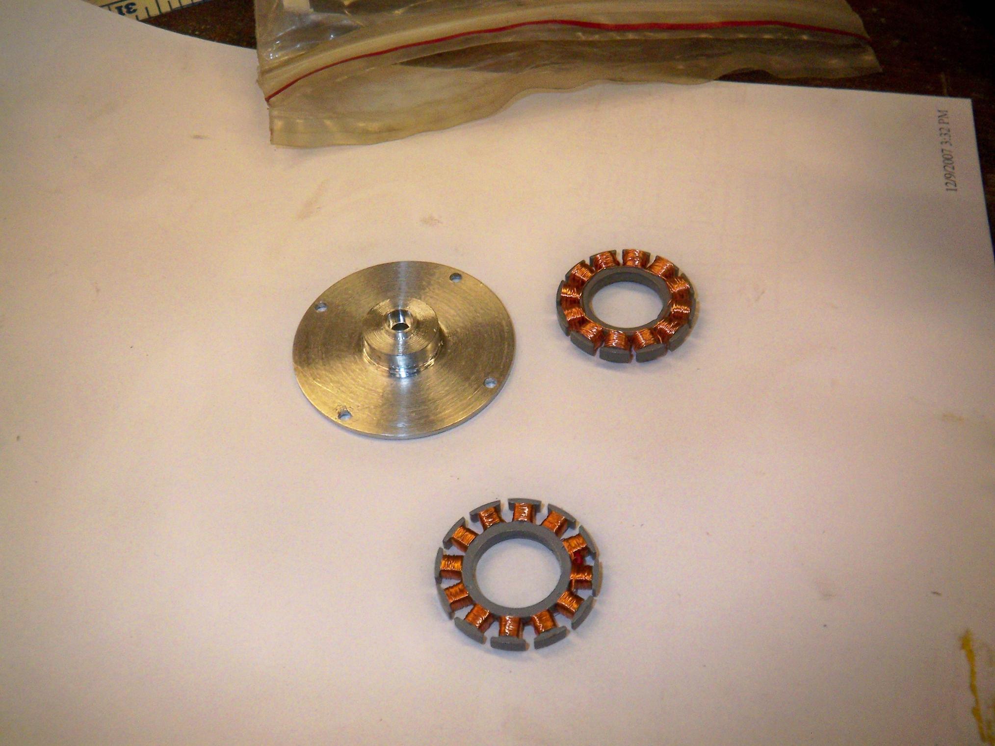
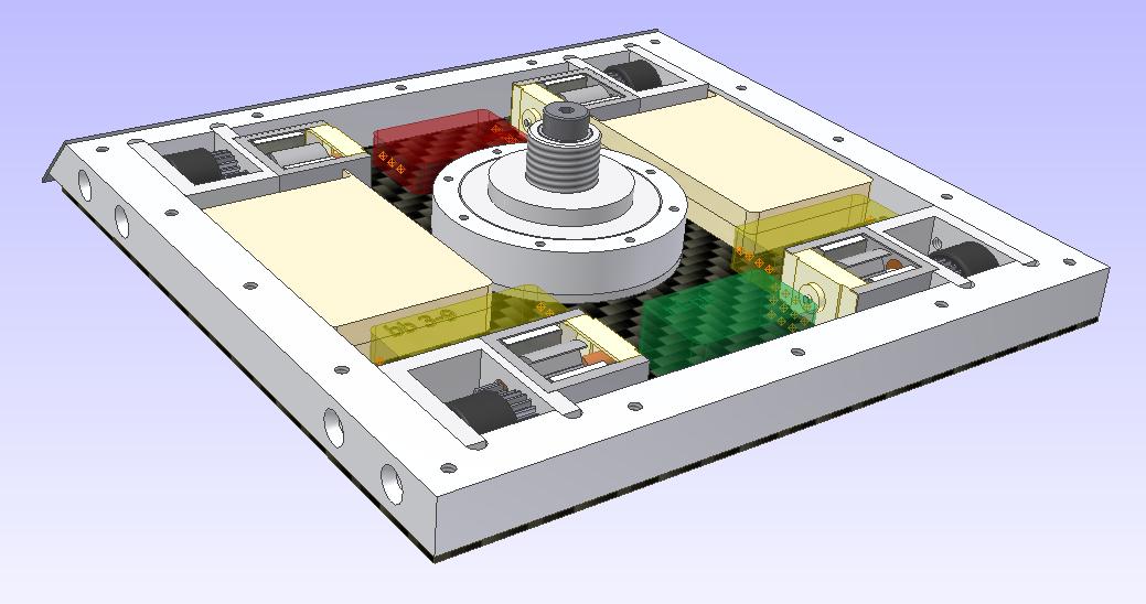
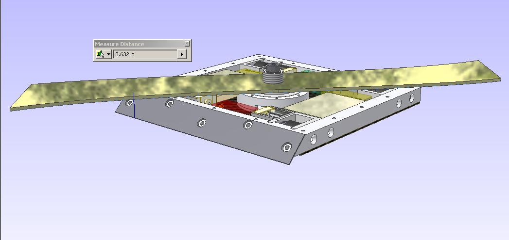
So the next thing to do was to start on the aluminum bits. Here’s the completed motor base. Or, rather, here’s a completed dummy motor base. It was a good practice run to get the quirks of manufacturing out, but ultimately there were some inaccuracies.
The MITERS lathe is well-known for being inconsistently inconsistent (consistently inconsistent would mean I’d be able to predict and offset appropriately to account for its behavior), and I had all sorts of weird things happen again, like the tailstock that points to any one of 5 constellations depending on where it is on the bed, how hard I crank the camlock, what bit I use, how I mount it in the chuck, how far out the tailstock ram is, and the phase of sunspots. And again, the toolpost proved troublesome – it’s awfully flexible for being a block of metal, and some times flexes slightly on cuts, which throws off the dimensions.
I might need to hit up one of the student shops for this application, which requires a bit of precision.
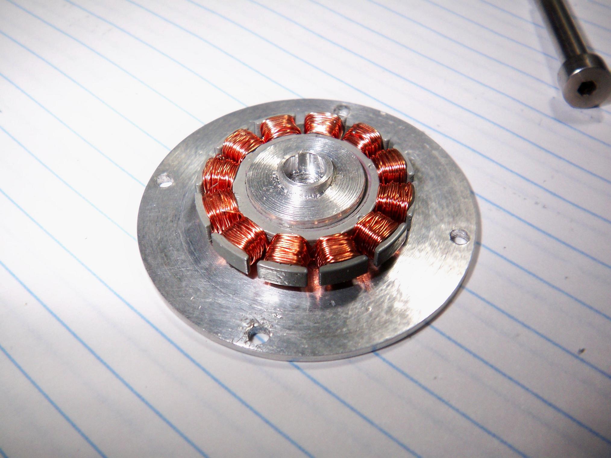
Assembled (with a stock ganked HDD stator). The stator is supposed be flush with the top of the stepped nub, but of course it’s 1.2mm too short to do so. This is actually not as bad as I make it out to be. The base, as it is, will make a good backup part, since there’s only a small amount of error on the OD and the depth of the center hole.
Overall, the test assembly confirms some of the hopes I had about fitting the motor can and maintaining space for the windings. There’s a fair amount of space to wind with.
More work to come!