The Dragon*Con & Robot Battles 2012 Recap

It’s over.

Again. And this time, it wasn’t total ass. This is probably made obvious by the fact that I’m making the recap report so soon after the event, as opposed to past years where I forgot about everything for, say, a month or two. Here’s how it all ended.

Überclocker (Unicorn):

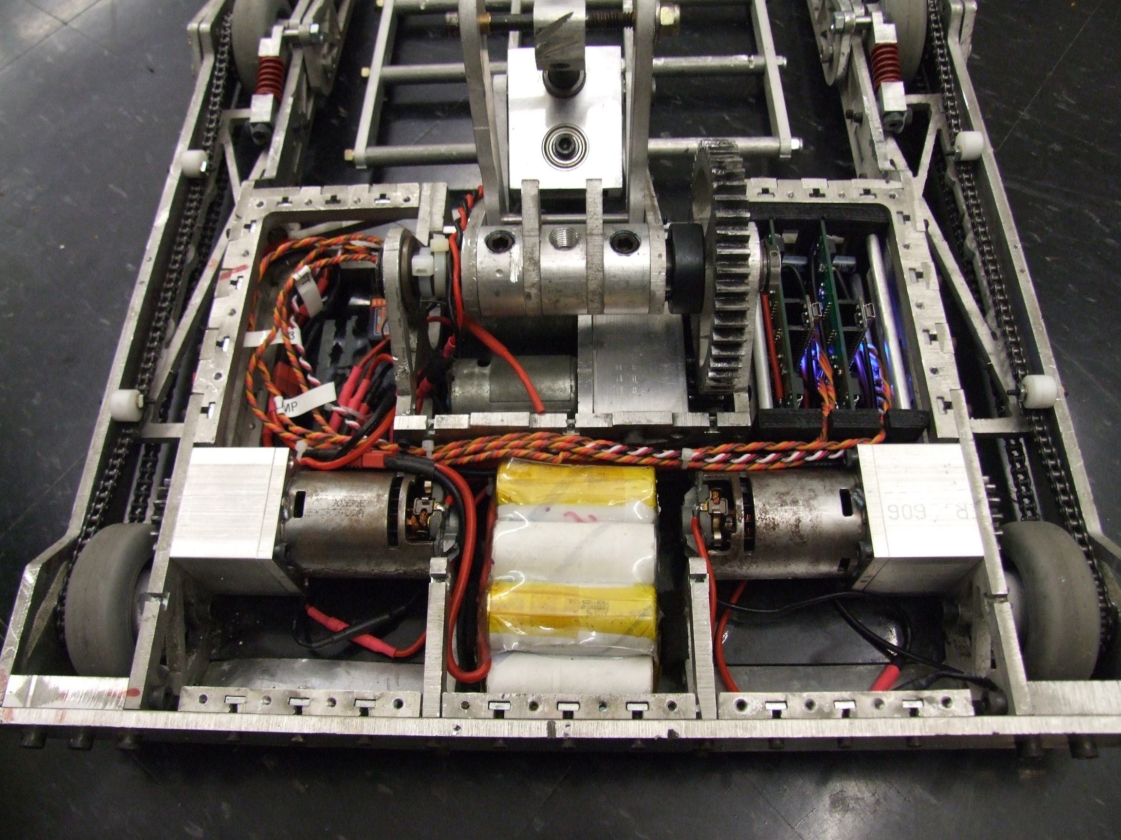
With a drivetrain that finally approximates reliable, Überclocker actually managed to win matches! Later in the tournament, however, and pretty much expected, the repaired fork gearbox began failing and finally left Clocker without the lift portion of the fork. I briefly was able to use the clamp as a lifter (due to the much larger motor now there), but Clocker ended up losing out of the tournament due to …. unscrupulous… driving.

Null Hypothesis:

Well, it sure worked well as a fast pushybot, so I can’t say it failed, but I just didn’t practice driving in confined spaces enough and most of NH’s losses were due to ‘stagediving”. However, it faced two other powerful drivetrain bots, and I think NH caught several seconds of combined airtime over the course of the tournament, finally losing just due to being outmaneuvered.

The Carly Rae Jepsen Wallbanger:

Oh, poor CRJ. It really only had 1 match in the 12lbers, due to the 12s being run single-elimination out of time constraints. But the one match was fairly good – it caught some air glancing  off Apollyon before getting pushed out, then whacked a few people in the 12lb rumble before getting scooped up.

The Ragebridges:

I’m glad to report that for the first time ever, all of my competition robots ran a full-custom motor controller design. The Ragebridges, with their Semi-Intelligent Current Limiting (a.k.a constant-current mode) worked flawlessly, and the CC mode came in so very handy when Clocker’s lifter gearbox shattered and stalled out both motors. I didn’t realize it at first, so I spent a few seconds pulsing the fork control stick up and down, which certainly could have smoked the motors if there was no limiting. None of the boards had the 15v instability and resetting issue after I changed the regulator inductors, and while they did get hot, there were no burnouts or smokage, probably aided by the CC mode.

But robots wasn’t all that happened. Quite a few things went down during the week, too.

The first mission was to get down there. Same as last year, I rented a car with a sufficiently large trunk/hatch, because air freighting or ground shipping were totally uneconomical (and I would have had to build a crate weeks in advance). Joining me this year with his large blue and green EV magic boxes was Adam Bercu, fellow robot builder of many years and also purveyor of fine murdered-out C80 “melon” motors. I brought along several demoables for the Electric Vehicle intro panel that we were hosting, including Chibikart2, the Kitmotters (demo stand and working motor from Johnscooter), and some random R/C parts and batteries. Adam took up the bigger end of the scale with prismatic Li cells, the giant Manzanita “micro” charger, and a large series DC motor controller along with other doodads.

The con itself was quite a time as it always has been. This year, though, I began noticing far more mechanical and home-built costumes and…. other things.

News flash: Eteks are now steampunk.

Update: Steampunk now officially meaningless.

As much fun as I make of steampunk, stuff like this still tickles me correctly because it shows that more people are getting down to building, no matter how silly and brassy it looks. The fabrication on this mono-tri-wheel-thing was pretty well done.

The same group also had a pretty sweet mono-moped with a ring wheel. Does this constitute a hub motor?!

IS IT STEAMPUNK!? I can’t tell any more.

Other mechanical costume parts abounded, like these deploying… something wings. Not too sure if they’re angel or paraglider or what, but watching it in action was awesome.

They were driven by a single motor meshing with a nicely finished geartrain. The drive parts were all waterjet-cut. This was present in the Waterjetting & Digital Fabrication panel, for good reason.

There was also plenty of more decorative elements involving LEDs and lighting on costumes. I’m not sure what the above character is (furry-rave-angel-quarterback-gunner?), but she had a very well made arm cannon doodad and plenty of LED accents everywhere. While throwing LEDs on things might not seem impressive to the average jaded engineer, for many people doing so is an introduction to hooking up a battery to a thing they made and having it work. That’s how it all begins.

I’m definitely supportive of more people making electronic and mechanical costumes and costume parts, and it kind of makes me want to do it more. I think I suffer a bit from costume one-upsmanship envy because I don’t want to start until I make a fully functional mech or something of that scale.

With the expansion of the Robotics Track to include the maker/hacker movement in general, I’m hoping to see many people make engineered costume bits in the future.

Besides the functional stuff, there was the usual plethora of paper mache and foam oversized objects. I’m fond of oversized tools, so here’s a giant wrench. Hey, one of those 3 is Alice Cooper, right?

Sadly, there was no space in the car for Excaliper, my giant 5.5-foot (real steel) vernier caliper that I brought one year and waved around.

Before the con itself, however, there were more robots. We didn’t go down a whole week beforehand just to sit around and drink sweet tea.

Above is Adam’s emergency 30lber build in progress. Nicknamed “Blitz”, it was built essentially over 5 evenings. On Monday immediately after arrival, we stopped by the area Harbor Freight and raided them of almost all of their 18v cordless drills. This was the same time I bought the cordless saws for Carly Rae Jepsen. The next day, we dropped by and bought some more.

A few days later, before the big show. Also present during the week was the other quickly-built-for-fun 12lber, Turboencabulator. Blitz’s design was based off the heavyweight champion Sewer Snake, which has a non-actuated extension of its main lifter weapon that swings forward when the lifted is driven under the robot, making for a flipper-like effect.

Also happening during the week was the installation of the new arena hazard in the Bot Arena, courtesy of yours truly and the arena build crew.

Yes, that is the secret thing I worked on through most of July and August. It doesn’t look very exciting from up top, certainly. In lieu of me explaining what is going on, it might be worth watching some of the antweights videos from this year (videos courtesy of Mike from Near Chaos Robotics)

I still need to put up an epicly long build report for this sucker one day.

This contraption is the control panel for the hazard. It has buttons and does things.

Let’s get down to robots. This is the new Atlanta arena.

Seriously. Isn’t it fucking gorgeous? Not only that, but it’s so outrageously modular. It takes a group of 4 guys maybe 15 minutes to set up if we have practice and tools nearby. Rigging the wiring for lights takes longer, but if you needed instant no-frills robot fight, that’s it. It’s also grown to nearly double the space, from 6 x 6 feet to 8 x 8 feet.

The hole. It’s supposed to have a 12″ sanding disc, but I forgot to bring it and nobody seems to sell those in the Atlanta area in a reasonable timeframe. So we had to make do with these little sanding pads. They fell off as quickly as expected.

If you haven’t figured out from the video, the turntable also goes up and down, creating a whirling pit of annoyance.

I didn’t get many good arena shots since i was primarily recording video. Plus, my free 4-year-old fake-DSLR doesn’t stand up to the professional and camera-penis-contestant photographers there anyway. Above is Dominant Mode briefly before it rocketed the pushybot most of the way across the arena.

The tournament this year was really boned for time – we were supposed to have 3.5 hours, but only ended up getting 2.5, and another event was scheduled to set up during out takedown/loadout time. As a result, many matches had to be cut short and the tournament had to be switched to single elimination mid-stream. Next year, though, this should not happen again.

The day after was the big day!

Again with the last minute random even details, the hotel sadfaced at the robots destroying the brand-new stage risers they had purchased just this year. As a result, a few dedicated builders put together a MDF and carpet overlay for the MDF and carpet stage riser surface. Steel plate annoyance bumps were also bolted to this upper layer, but not very securely – the 30lbers started plowing them off one by one.

There were too many 12lbers to run double elimination, but the 30s ended up being double.

Carly Rae Jepsen Wallbanger lost once to Apollyon for a net 0-1 record.

Überclocker won against Nyx and subsequently won against Scary-go-Round before losing to Pinball and then Nyx, for a 2-2 record.

Null Hypothesis faced Pinball immediately and lost (but not before catching some serious air by ramping off the front wedge of Pinball), then lost to Nyx, for a 0-2 record.

The carpet ended up being a little fragile on its own with no strong, bonded substrate (unlike the stage riser carpet). By the end, there were so many holes and tears in it that the duct taped used to fix the stuff became a hazard in its own right. The lint was also very tenacious and got into drivetrains. Quite an interesting element to add to the game, though the builders are now thinking of a better solution for future years in case the hotel requests stage condoms once again.

Yes, that is a sword on Clocker. After all, I did name it Überclocker Ünicorn, right?

After my match with Scary-go-Round, the lifting fork was pretty much totally useless. Both of the gearboxes had shattered completely from the impacts and the motors were totally locked up. I got as much postponement time as I could in order to pull the gearbox and take out the broken gears, a process which took about 20 minutes exactly as I found out. I restored one gearbox to functional status (leaving the other one freewheeling) , there was not enough time to put it together for the Pinball match.

The top clamp has enough force to lift 30lbers, so I just needed an extension to get it to the ground. Hence, emergency death-shank provided by Jamison. It worked exactly once, but not really.

Next version of Clocker is designed with serviceability in mind…

The carpet also destroyed the McMasterbots wheels. Clocker managed to grind the two back wheels right down to the plastic core, which compromised its traction a fair lot near the end. These wheels are clearly one event use – they’re too soft to just leave on, so I guess I need to make them easily replaceable and have plenty of spares hanging out.

videos

I’m glad to say that many people besides just me had cameras at the events, so Clocker and crew have alot of footage from their matches. It’s almost to the point where I don’t have to do anything!

I’m waiting on some video from other people before editing together my own bots’ summary videos, but in the mean time, NCR has a list of almost every match, and Dale’s Homemade Robots has several compilation videos.

outlook for the fall

That’s it. My annual robot party has ended, and it’s now back to the grind of taking classes. This fall I’m going to play a bit of a catchup game in that regard, so I’ve promised myself no large engineery things. Let’s see how long that lasts.

Clocker will be dismantled now, to force me to rebuild it. The earliest I might be able to call it is Motorama 2013, in February. NH will be kept totally as-is, but it won’t go to Moto 2013 (the only category it would be legal in would just make it be more disassembled, not necessarily reversibly so). CRJW might become the inspiration for a new true “melty brain” translate-while-spinning bot next year.

This semester, I’m going to focus on little things which don’t need time spent fabricating. It would be nice to get the Ragebridge boards compactified more and get rid of the discrete Arduino (or “the ATMega328 breakout board” as some have called it). Not to say it won’t use the current Arduino code, but the chip will just be integrated on board. I’d like to reduce the square footage by 25% or more this way. I’ll also try to characterize the Semi-Intelligent Current Limiting some more to see how fast and effective I can make it. Given the discovery of mismatched component values and incorrectly placed parts, tinyTroller might make a reappearance since it has the same power side architecture.

Next, it’s my intention to reduce my gargantuan pile of robot debris some more. I’m currently split between 4 different shelves and storage locations, and even those are becoming hard to handle… I may put quite a few things up for sale here, and if I do, they will be on a separate page.

As for the distant future, next Dragon*Con I intend to make more appearances at the Maker/Robots track. I do want to run Resources and EVs again, but also I want to add How to Shop on McMaster-Carr… one of the seminal skills that hobbyists and amateur engineers have to learn that really makes projects nice.
The Dramatic Story of How I Saved the Ragebridges and Suck at Reading Datasheets, and an Überclocker Update

Alright, here we go. The post where I have to fix everything, because I have to leave for Atlanta and Dragon*Con 2012 (and its associated Robot Battles) in 8 hours. After assembling 2 more Ragebridge boards, finding that all of them had Resetting Regulator Disorder, I tried several increasingly desperate hacks to get the boards reliable before discovering a small nuance in the datasheet. In all, I managed to blow up another board (due to a slight… assembly problem), but I believe I have finally found a stable operating plateau for the Ragebridge boards.

Oh, and Clocker works. Here’s a recap:

One of the first problems I had to solve before actually getting to work on the Ragebridges was how to mount them. Formerly, Clocker’s “eBays” held 2 Victor 883s each. I wanted to group the Ragebridge boards on one side of the bot to avoid having to have long runs of distribution wiring, and because mounting two mostly bare PCBs horizontally greatly increases the risk of robot grunge getting places they shouldn’t.

I couldn’t really stack two of the Ragebridge boards horizontally, though, because they were slightly too tall to accommodate the thickness overhead of mounting standoffs. If I had shorter capacitors, this could have worked fine, and I was planning on building a small enclosure around the boards with fan cooling.

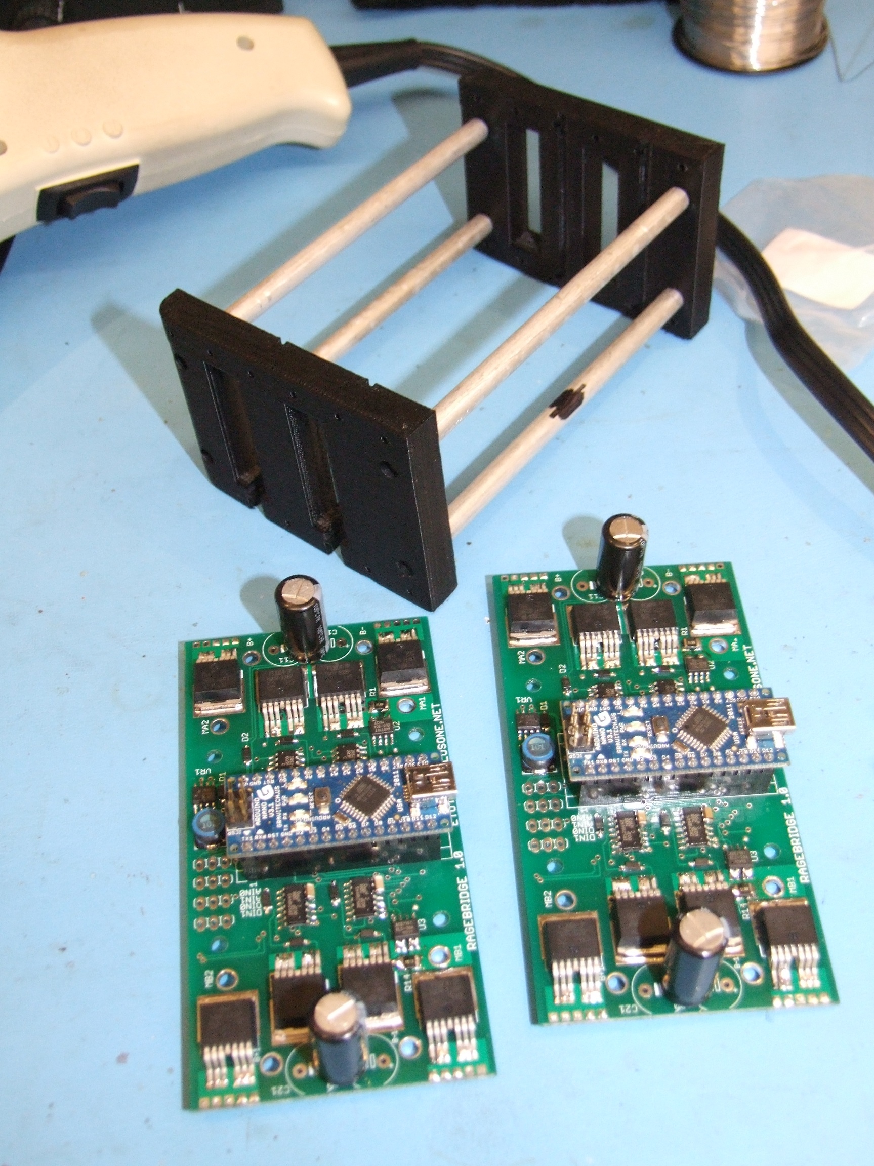
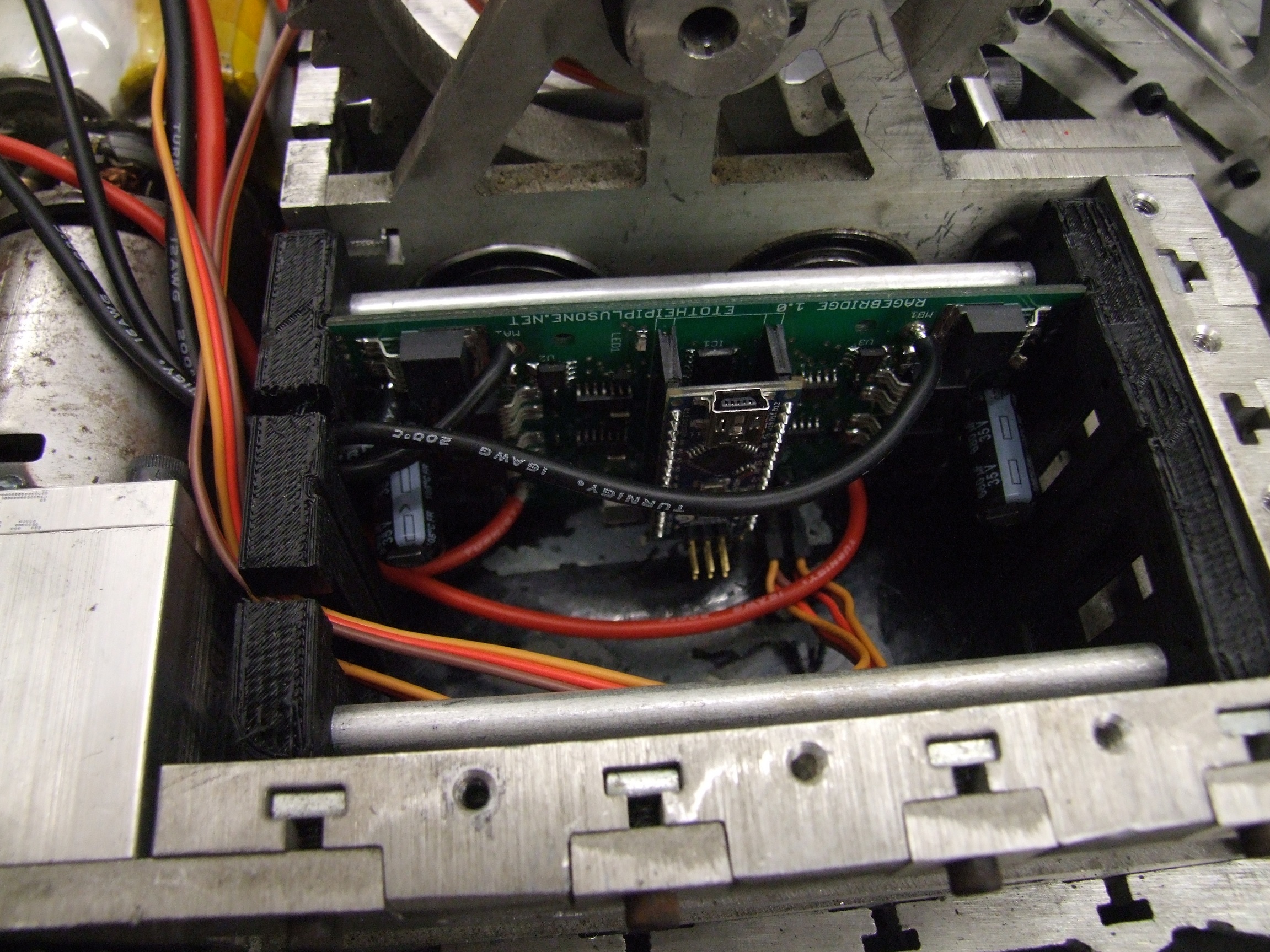
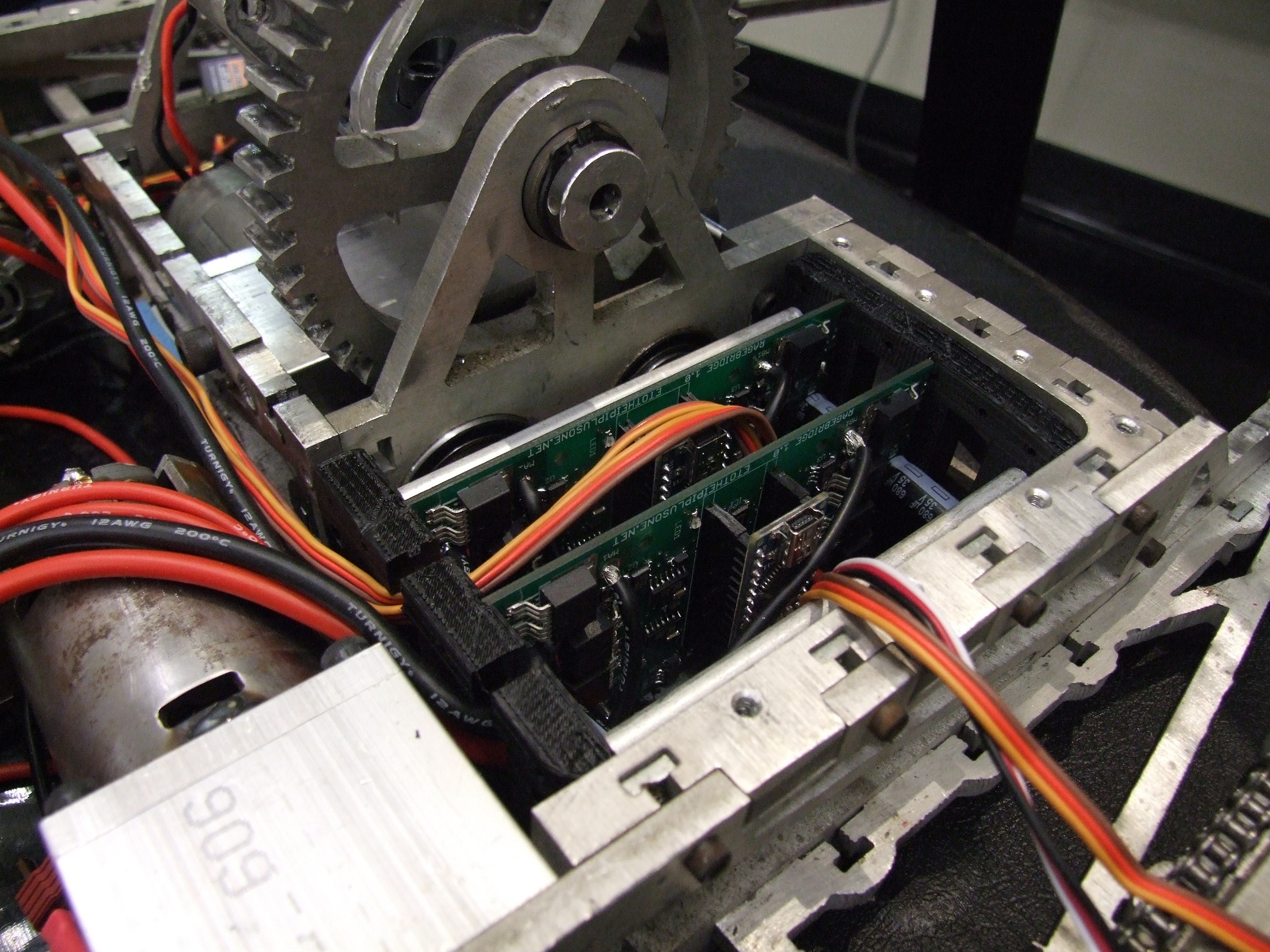
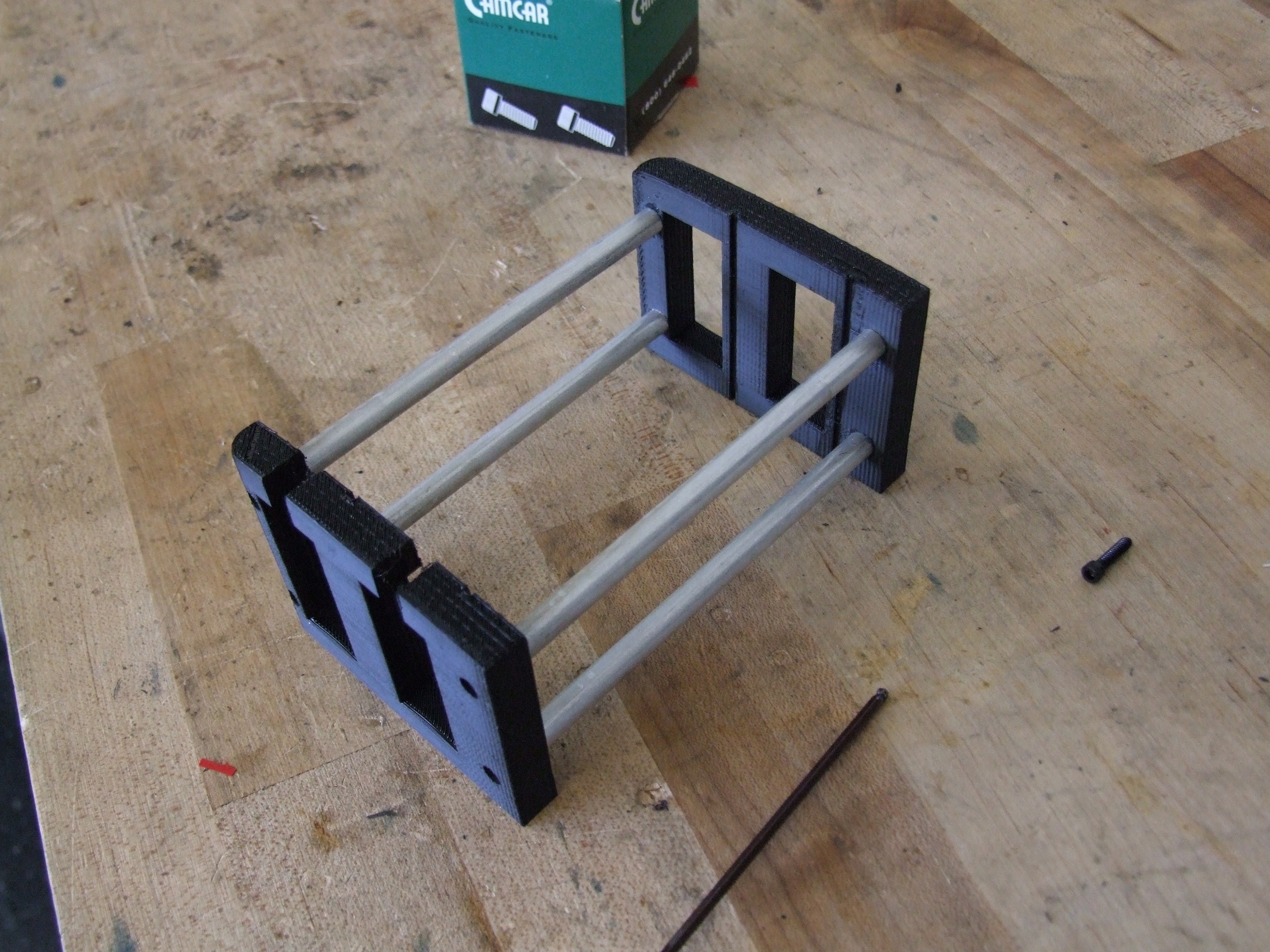
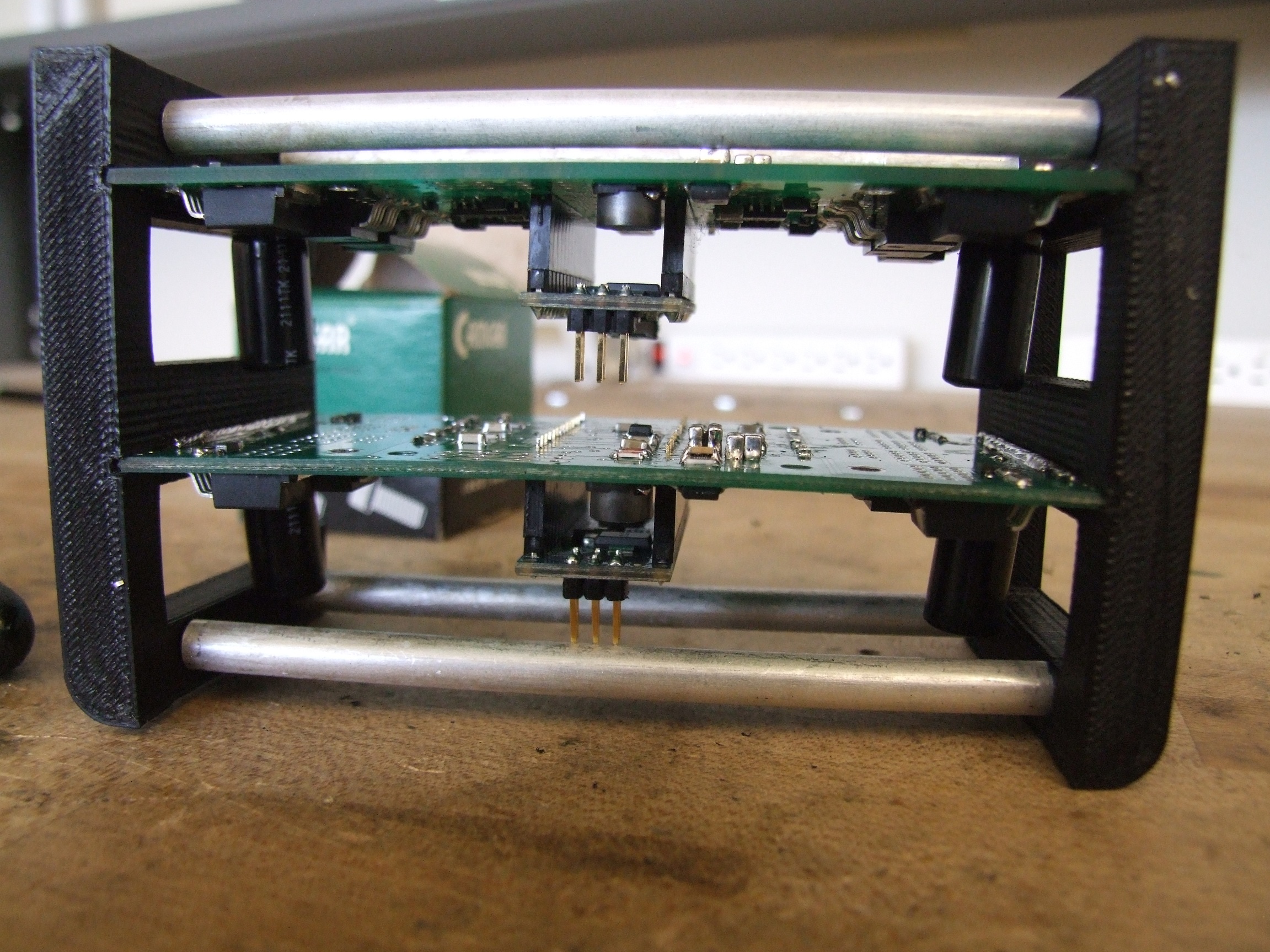
Then I realized that the boards are just short enough to mount vertically. I still needed a way to retain them, though, so cooked up very quickly this “rack” that has slots which the boards fit in.  This was whipped out on the Lab Replicator™ and the standoffs made with a lathe.

First tries always reveal where parts run into eachother. On the upper board, the capacitors on the underside touch the standoff above them. And on the lower board, the Arduino Nano’s ISP headers touch the standoff below them.

Hmm.

The second revision moved the boards a little closer together and away from the standoffs. With the mounting solution taken care of, it was time to attack the boards themselves. I first had to attach wires to them:

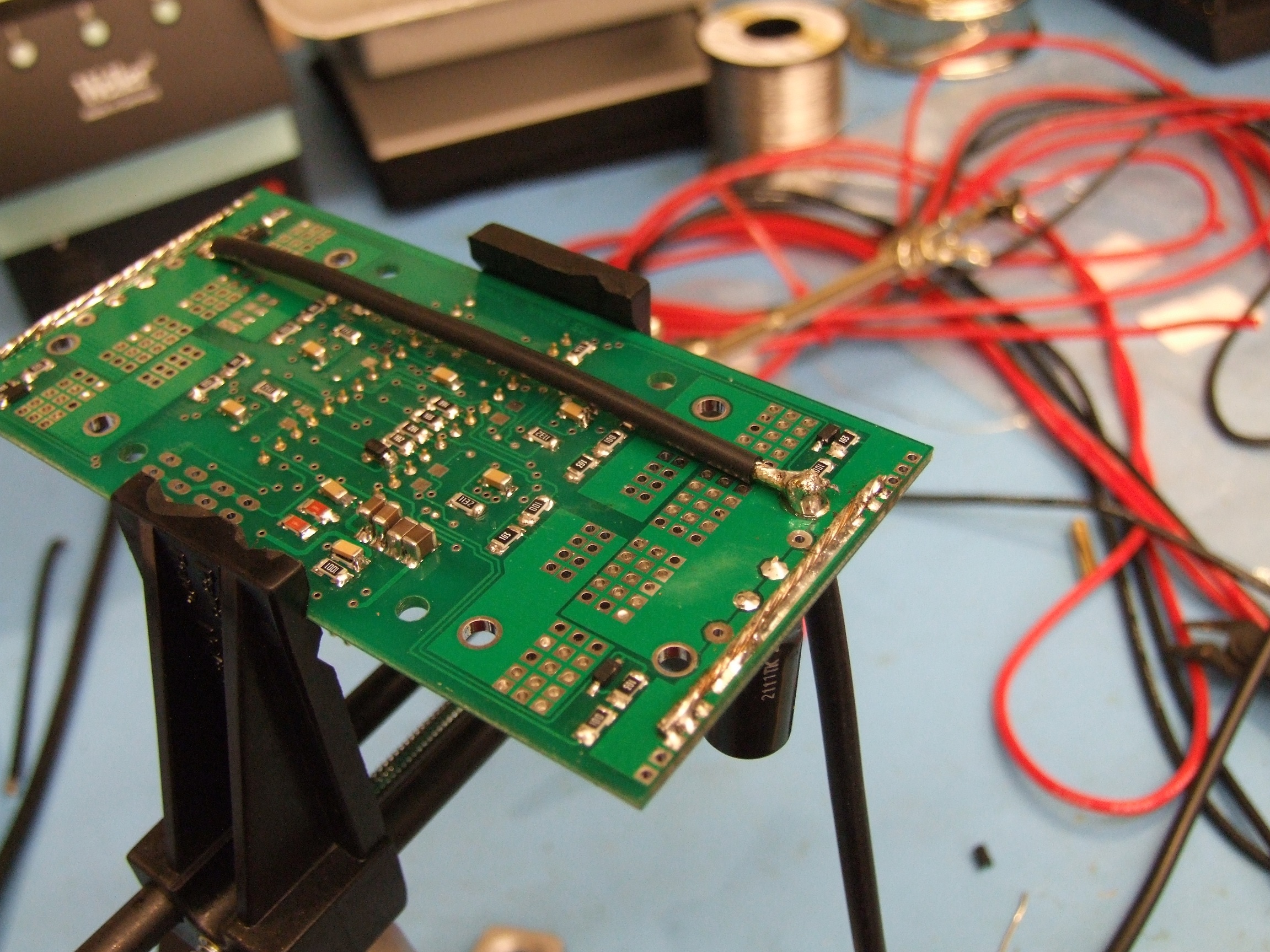
Instead of soldring wires to both battery inputs and then joining them in parallel, I used a single 12 gauge input wire and then a 16 gauge ‘jumper’ which brought power to the other half of the board. The constraints of rack-mounting my controllers this time meant I couldn’t make big Y-cables.

After populating the boards, I began to run into regulator drama yet again. With my Spektrum receiver (Clocker’s receiver for 3 years now) attached, the LM2594-based switching regulator wouldn’t. This was worse than it was on Null Hypothesis (details in the middle) where it seemingly had a habit of not wanting to power cycle. The 15v rail was totally unstable, and the 5v power LED on the Arduino nano would flicker as the regulator kept latching up and resetting.

Even with the Arduino Nano but no receiver, it was still erratic, taking several seconds to stop resetting the microcontroller. The whole time, the regulator was also getting hot. Extremely hot.

Both boards displayed the same symptoms. When the regulator was in latchup mode, the switching frequency was audible and also very unstable. Basically, it seemed that any load was causing the whole thing to go crazy. I began attributing it to being a design error on the board or in the layout – maybe I had crossed my grounds somewhere else?

I began pulling desperate hacks suck as capacitance in places where it really should not have needed capacitance (i.e. where a slightly out of spec component value should not have a first-order effect on functionality), and even hacking a 7815 linear regulator onto the board to test if it worked at all (Result: Yes, the board itself is fine, and the linear regulator would be also fine if I wasn’t wanting to run 30+ volts).

Defeated for the night and about to switch Clocker back to Victor 883s, I read once more through the datasheet hunting for possible thermal limitations or some indication that I had totally fucked up the component layout and selection. The datasheet had a section on inductor selection, which I’ve handily ignored in the past. Within it was this equation:

Okay, sure, let’s try it… For my setup, with Vin = around 25 volts and Vout = 15 volts, I got a V-us value of 38. Now let’s see the inductor selection table:

Oh dear.

For as long as I’ve used the LM2594, I’ve just tossed a 100uH inductor onto it because it was cheap on Digikey for the package size I designed with initially. And for as long as I’ve used the LM2594, it’s always been a nervous wreck.

My voltages and load clearly put me in 330uH territory. The microcontroller and receiver combined generally draw 50-70mA combined, with the beefy Spektrum receiver demanding 100mA when it is searching for a transmitter. So for the purposes of modelling, 0.1A is a good number to use for load current.

So what does too-small an inductor do to the system? Several possible things. First, current can change (ramp up or down) faster – there’s less “mass’ to it, so to speak. Second, as a result, the regulator can enter “discontinuous” mode, where the energy needed by the load per switching cycle results in a duty cycle so small that the current (which can now change faster) falls to zero instead of continuing to flow (“continuous” mode). The LM2594 should be able to handle discontinuous; but next, because the current can change faster due to the inductance being too low, it could very quickly reach a level which throws an overcurrent fault in the LM2594 regulator. In other words, it wakes up, turns the inductor on, goes OH FUCK, enters shutdown, wakes up, turns the inductor on, goes OH FUCK….

This really all speculation, but the observation that most supports the inductor-too-small theory is the fact that the LM2594 only reduces its switching frequency if it is in the overcurrent condition. I shouldn’t be able to hear it otherwise. I tested this by finding a voltage input which would run comfortably at 15v out and 100uH – about 17 to 18 volts seemed to do it. And there were no problems whatsoever. As soon as I crested about 20-22 volts, though, all hell would break loose.

Well then.

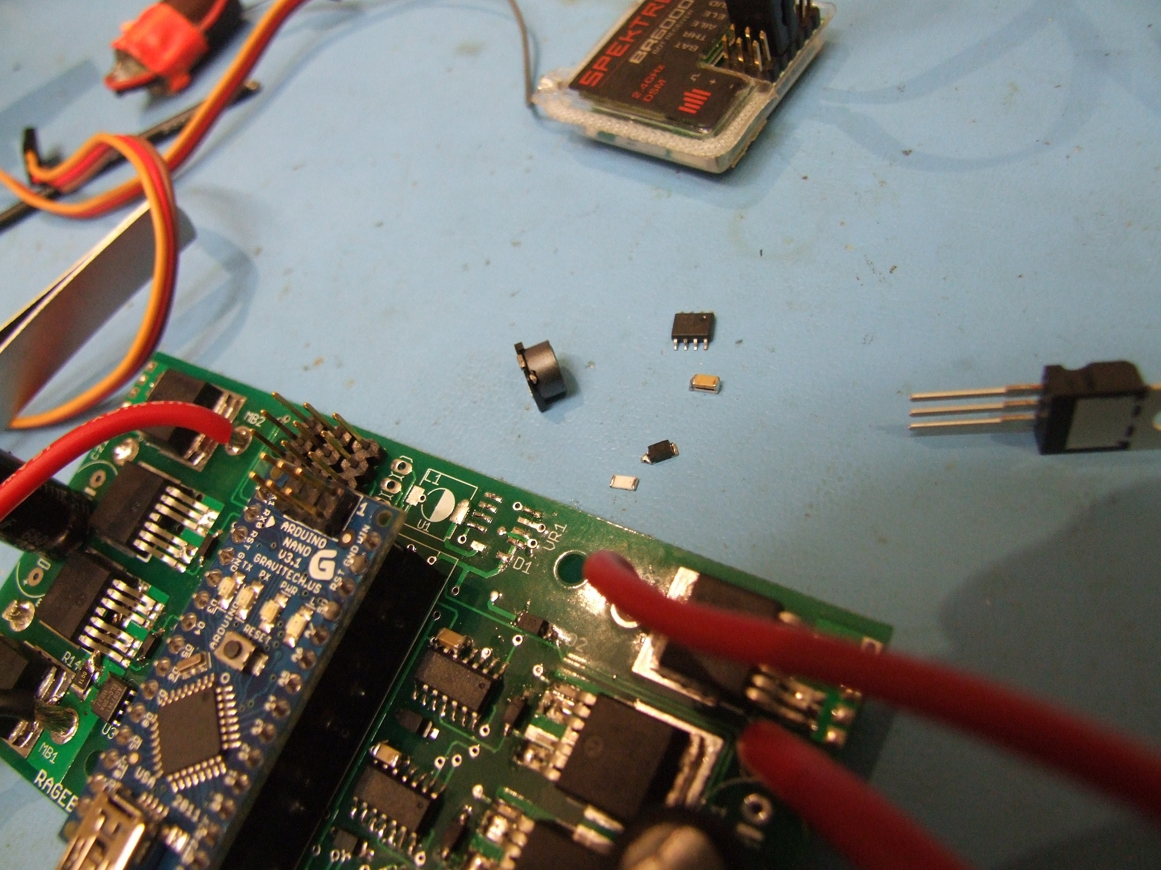
Could I have been defeated by just not reading the datasheet? Let’s find out. Luckily, I had some 330uH through-hole inductors left over from the construction of Segfault’s controller long ago:

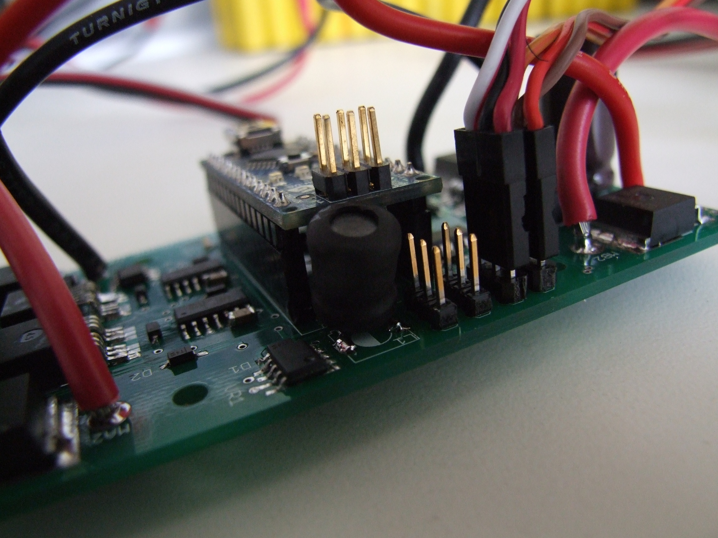
Through hole, surface mount, same thing… just some bent legs.

This was the only change I made to the whole regulator circuit – all of my other hacks had been undone by this point, because I wanted to make sure there were no other layers of mods that needed to be made. Surely just an out-of-tolerance component value cannot be the root cause of my controllers’ undoing!

Except it was.

Whatever, I’m just gonna stuff it in the robot.

I’ve yet to experience another hiccup or reset since replacing the inductor. At all – the only thing which causes a reset is a sudden applied load on the logic side – plugging in the Spektrum receiver when the board was not doing anything previously, for instance. In *that* case, certainly more buffering capacitance could help, but if the receiver is suddenly plugged in during battle, something has gone very, very wrong.

I test drove Clocker for a few minutes in this configuration (only the drive – the other controller isn’t installed) just to test the robustness of the fix. This test included several power cycles both “hot” and “cold”, to see if the thermal issue could have been part of the problem. The regulator does still get hot, but it seems to be a normal hot.

It’s time to install the next board! By this picture, I had already pulled the 100uH inductor off every single Ragebridge board current in existence and replaced them with the 330uH thru-hole ones. I was now test lifting various chairs and handtrucks with Clocker.

Playing with the current limit setting, I got the main output gear clutch tuned to the point where the bot could quickly lift 30 pounds on top of the fork, but if I stalled the fork against the frame, there wouldn’t be enough current to do any damage. The way it was accidentally tested was by wiring up one lift motor backwards so the two motors were fighting eachother the whole time, while I stared dumbly on and went “Hmmm, I wonder if something’s jammed”. I am vaguely glad for the existence of (my and only my) current-limited controllers.

The prescribed current limit for the fork is 30A, at which point the two motors will produce 50lb of upward force at the tip of the fork.

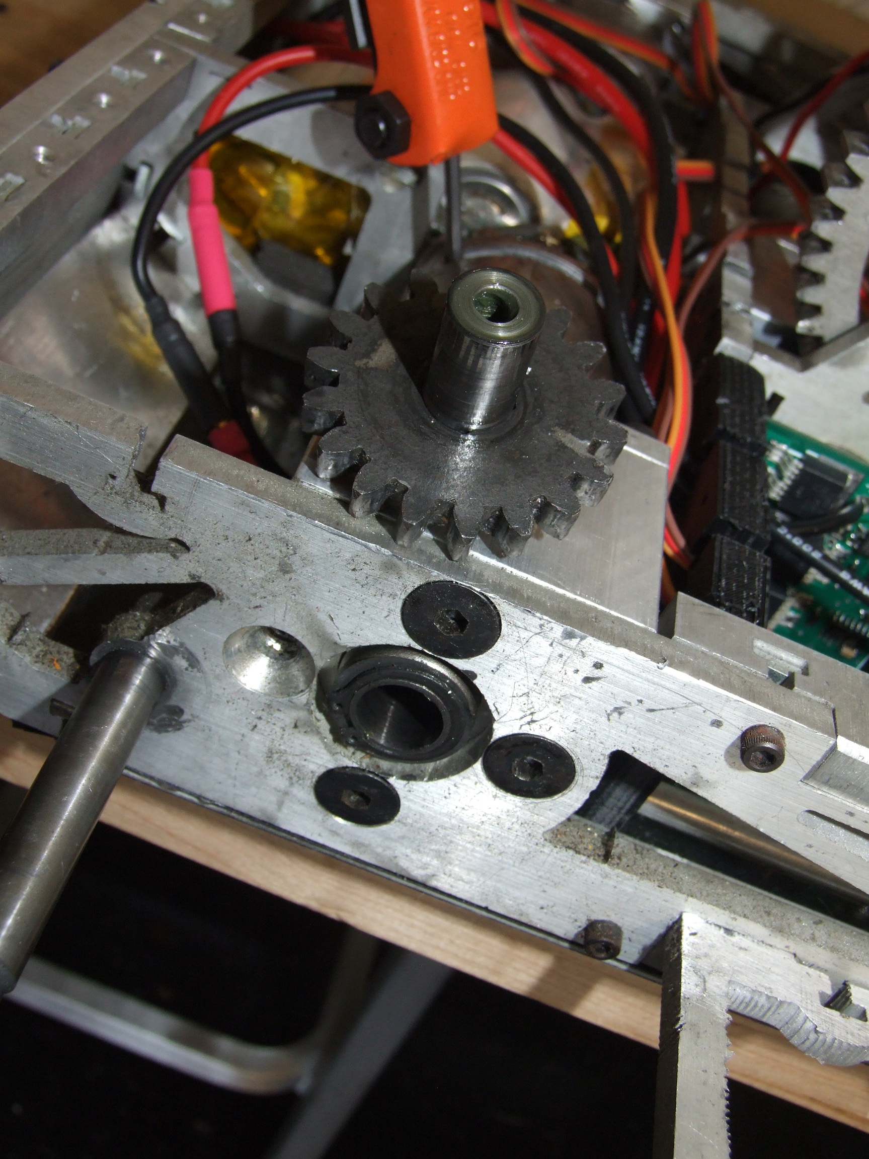
Alright! I’ve fixed the electrical problem, so let’s bounce the problem back to mechanics. That is my right side output gear, not being where an output gear is normally found.

How did this robot *ever* work?

Remember at Dragon*Con 2010, the left-side output shaft of my custom DeWalt frakenboxes lost its shoddy press fit, leaving the bot mostly immobile. That side was repaired by knurling the output shaft where it meets the planetary gear carrier, and it hasn’t been a problem.

I’ll admit that the discovery of this problem was just a little unconventional:

Hey, if it has a current-mode, I’m riding it, okay?

Definitely a useful way to stall-test your drivetrain. Each drive side’s current limit is set to 55A, which actually seems kind of low for the DeWalts. They definitely want more when spinning up. Maybe I should have double-bypassed the current sensors to get peak 90A limits, but then I’m pushing the board’s physical layout in terms of current density in the copper layers.

During some enthusiastic turning, the right side suddenly stopped producing torque, and I heard the dreadful sound of “motor spinning up unloaded”.

How did this robot EVER work?

Clearly the answer is it never really worked, if I’m hammering out one problem after another. I repeated the knurling and re-fitting operation on the right side, and all was good.

Now let’s return to the electronics.

During another driving and lifting stress test, something exploded in the bot.

Crap. It’s already like 3 in the morning by this point, and I’m wondering if now that the fundamental disability of the controller has been solved, the problems have moved down the line to the next weak link. Now, the controller that bit it was the drive controller, a.k.a the one I did all the nasty experimentation on before finding the inductor issue, so maybe it’s just weakened from being an experimental subject.

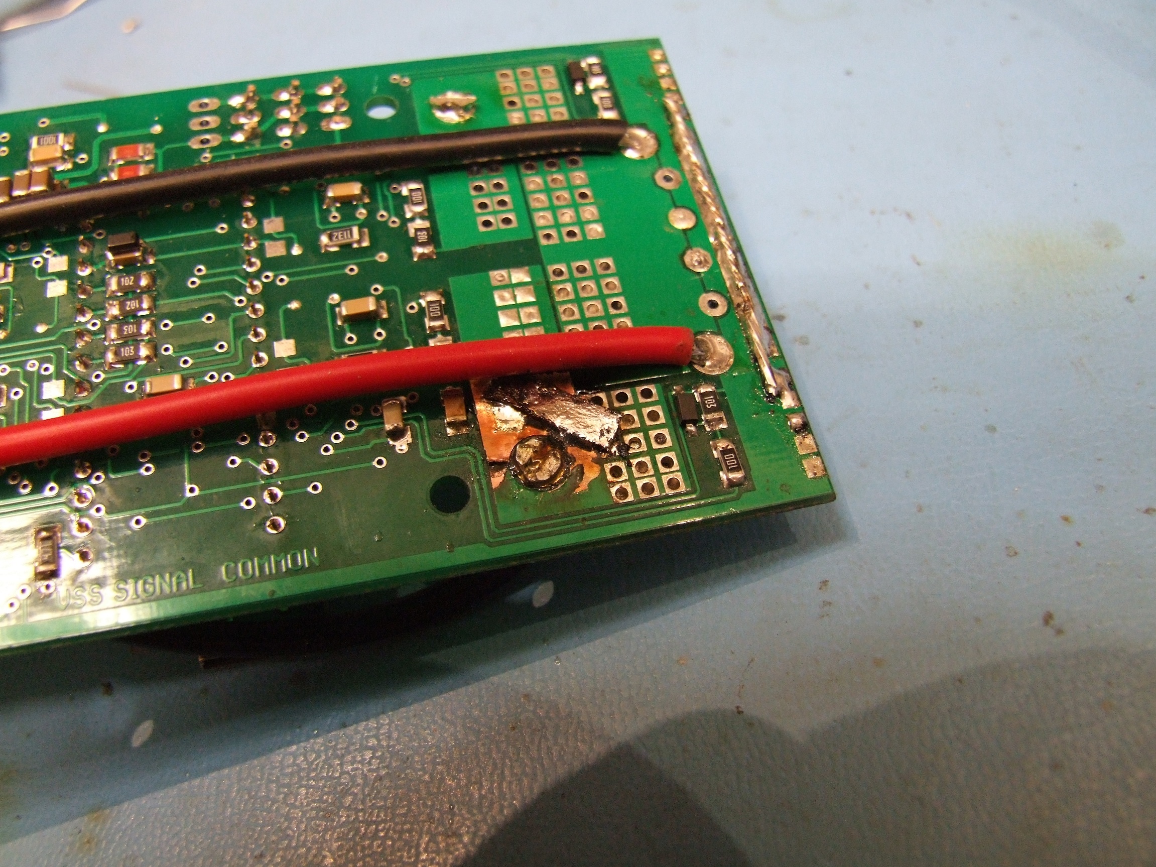
The failure was just indicative of massive shoot-through. Aren’t my gate drivers supposed to prevent that? What could possibly cause the FETs to suddenly overlap with disasterous consequences, besides like, leaving half of the gate drive chip unsoldered because I forgot to go back and solder all the pads after anchoring it?

Oh, it was that? Okay, carry on.

Here’s the final wiring arrangement for Clocker. It looks kind of like the same jumbled mess as it has been, but the wiring runs are alot better packed.

I made another spare battery afterwards, because this pack is getting high in years (and in number of dents in the cells – a little disturbing). Not only that, but Clocker has no less than 3 550 class motors and two DeWalt motors now, so it’s more stress on the battery than ever. It’s not going to run back-to-back matches for sure, so I need to have a swappable battery.

Here’s the bot all closed up for this year!

And now, a bit of test video, showing some more handtruck yoga.

So that’s where all those dents in the cells are coming from.

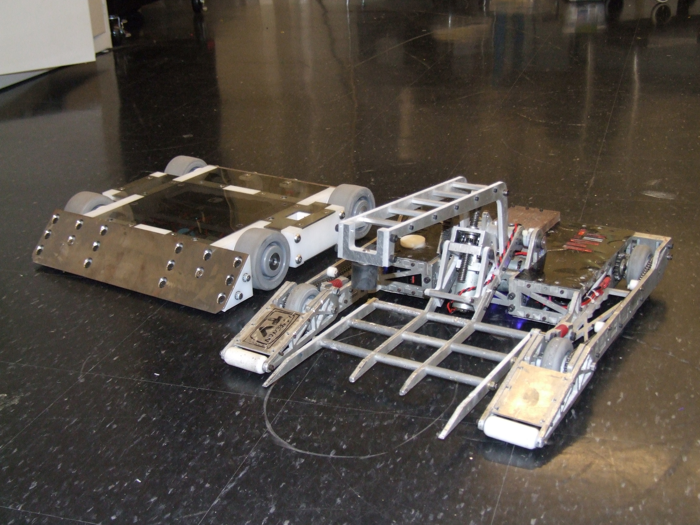
And here’s a shot of the 2012 fleet: Null Hypothesis and Überclocker Unicorn. Sorry, the nickname just kind of stuck – and it was also partially inspired by the fact that Gundam Unicorn is a real thing.

So that’s it. 30lbers only this year for me, with none of the ants and beetles returning. Instead, I have become the arena; more on that later!

Dragon*Con 2012 Schedule

Observant attendees will notice that I am a panelist in the Robotics & Making Things & Engineering & We’ll Find a Snappier Name For This Next Year track. It’s been a long peeve of mine to go to conventions only to discover that all the panels suck, so I’m out to fix it. In the past 2 years, I’ve been complaining that nobody really had a panel focusing on the where to get and how to use (not to mention the even go want to do look more like) – the resources of engineering projects, which for me at least was perhaps the number 1 contributor to actually being able to get nice stuff done. What to buy, where to buy it, where to scrounge and salvage it if you can’t buy it, and why it doesn’t work the way you think it does.

So I’m proud to announce the MAKER RESOURCES panel, which will probably be something like all of my Instructables slammed into an hour. Focusing primarily on parts procurement and fabrication resources for the non-shop-endowed maker, I’ll also touch on design software and design methodologies.

Next is the ELECTRIC VEHICLE TECH panel, co-hosted by real EV guy Adam Bercu. My role on this panel will probably be dealing with the smaller end of rideable objects, discussing the nuances of using hobby R/C parts and shitty e-bike controllers. We’ll likely cover basic EV drivetrains and power system choices as well as math for estimation and calculation of drivetrain properties. Basically, 2.00scooter in an hour except probably more 2.00motorcycle.

I’ll also be on the DIGITAL FABRICATION AND WATERJETTING panel along side long-time robot buddy Simon Arthur (some of you may know him as Big Blue Saw), in which we’ll touch on ways to abuse the waterjet and laser cutter, and the coolness of digital fab in general.

The 1100-mile haul begins soon.