What do you mean Robot Battles at Dragon*Con is in 3.5 weeks?!
Again? I swear they move the thing up one week every year just to surprise me. Actually, it’s more like 2 and a half weeks before I get to Epic Road Trip once again from Boston to Atlanta (ideally not through The Sprawl) and temporarily set up base camp at the Invention Studio. So maybe it’s time to start on a robot or something.
Luckily, I’ve actually been working on Null Hypothesis on and off for about a week. As explained in its introductory post, I was needing to separate a large 8 x 48″ panel of 1″ thick UHMW into slightly funny-shaped bars with the waterjet. I test cut one of the less important frame pieces to check for quality of finish, and determined that only cutting on the highest quality was going to even have a hope of getting through the material. UHMW is notoriously hard to do anything abrasive to since it resists abrasion really well.
One mistake I made but only realized later is that I was testing that piece on a setting meant for polypropylene plastic, which machines much easier – one of the most machinable plastics.. Every material is assigned a “machinability” value in the OMAX software, and this is one factor in controlling how fast the jet moves – and cut quality is pretty much a function of slow. Even “generic” plastic and acrylic-specific settings have machining speeds around half of polypropylene. Therefore, I elected to just throw the panel on the machine and hope for the best using the highest quality finish.

By the way, cutting a mushy plastic like UHMW – or any plastic, really – causes a disgusting film of plastic goo to cover the surface of the pool, because the particles both float and stick together. I was skimming handfuls of plastic snot out of the tank as the job progressed.
The job took an hour and a half, which I can’t really say is much faster than me cutting off a bunch of barstock like I would have done Back In The Day. I had bought enough UHMW barstock in the correct size (1″ thick, 2.5″ wide) to make most of the frame anyway because I was uncertain that the huge panel would have been useful. But, with the combination of very high quality cut (slooooow) and actually selecting the correct material properties, the frame pieces came out very smooth and square. I was otherwise prepared to redesign the frame a little to get rid of those hard internal square corners and slots to relieve me of the extra machining.
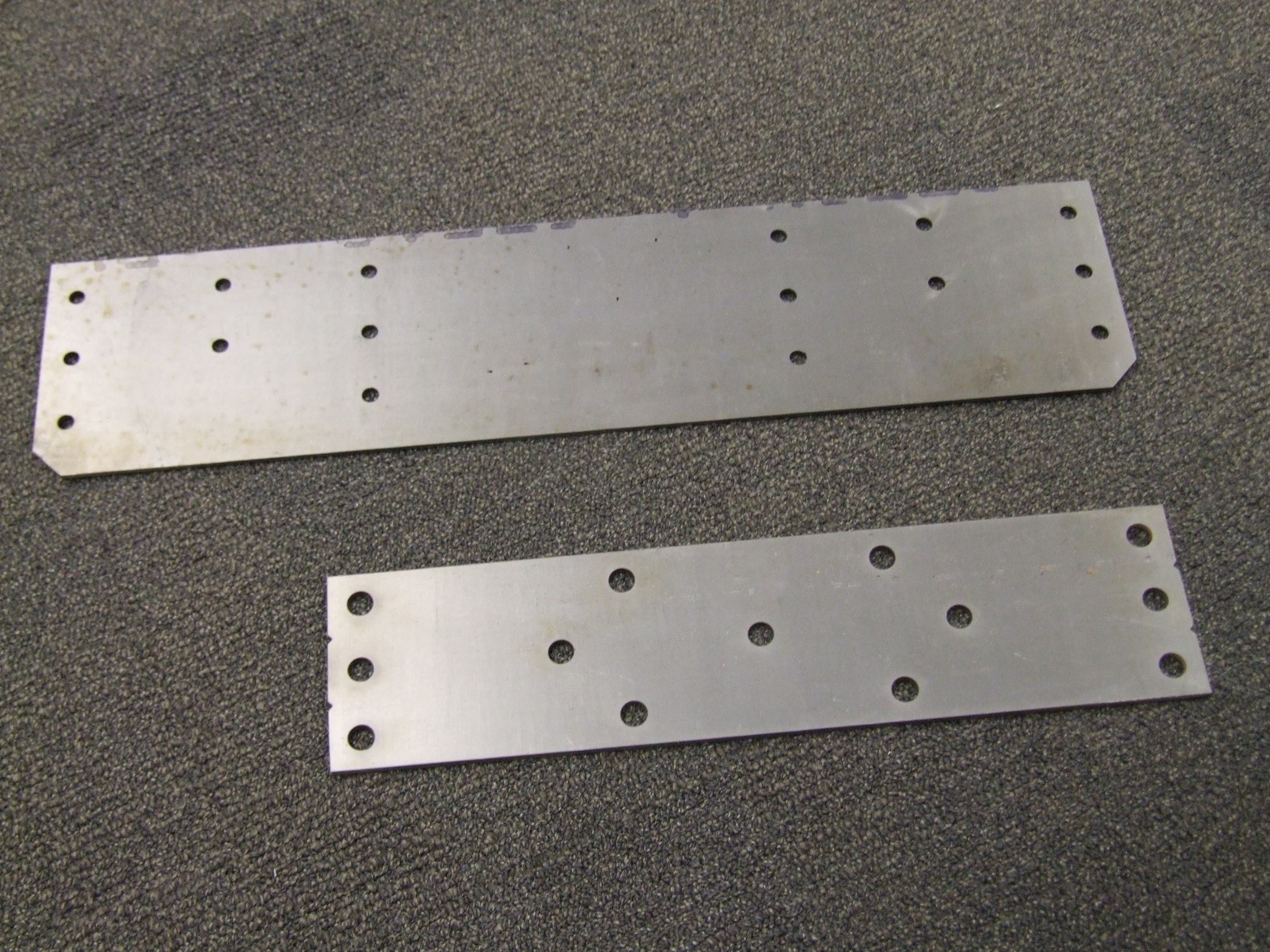
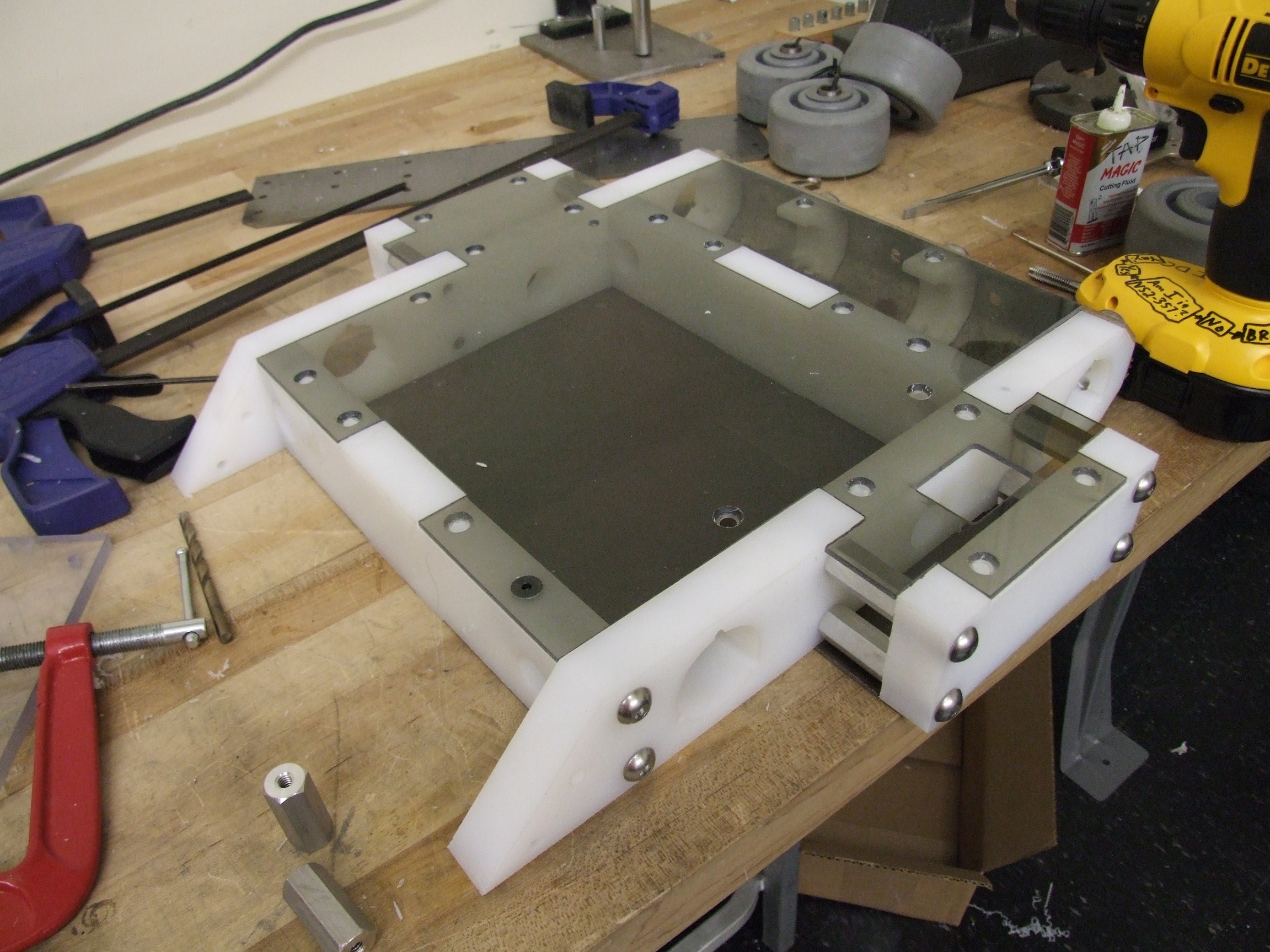
Also on deck in the same session was the front and rear steel parts, the top and bottom polycarbonate covers, and the internal electronics mounting structure. Above are the front wedge and eventual rear bumper thing. Both are made from annealed 4130 plate steel purchased from McMaster.
While I don’t really have facilities big enough to heat treat these plates short of throwing it on top of a gas fired barbeque grill for an hour, buying a plate of generic mild steel was actually more expensive – a 6 x 36″ plate of 4130 in 1/8″ thickness costs $36, whereas generic 1018 steel in the same dimensions is more like $50. Strange, given how much more versatile 4130 can be – not only is it stronger even in annealed form than mild steel, but I could harden it to the high Rockwell C40s.
I attribute it to McMaster knowing what people buy most frequently and giving those product some… extra markup.
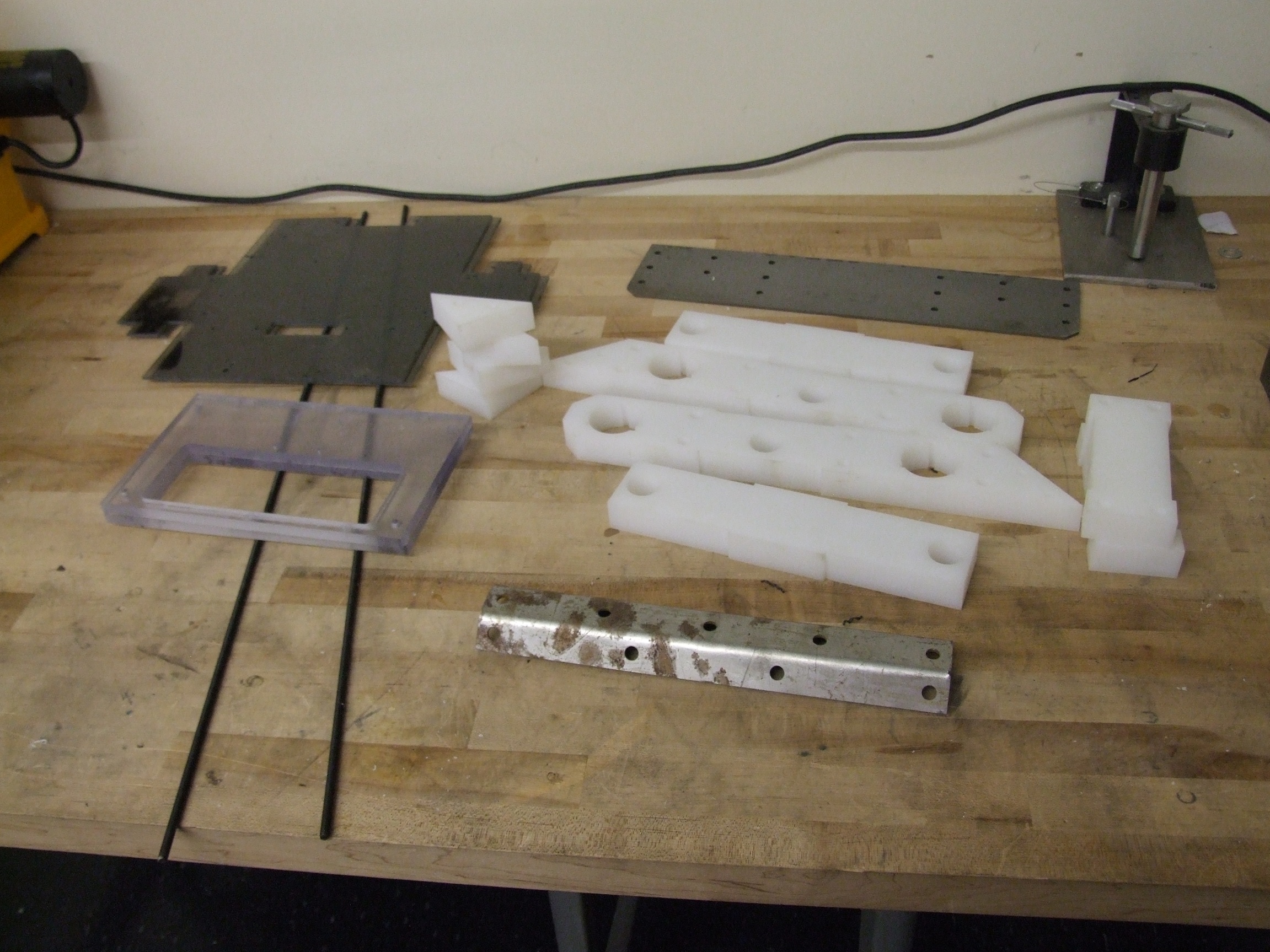
Here’s the pile of structural parts. The top and bottom plates are 1/8″ polycarb, and the supplementary electronics armor is 3/8″.
I’ve pre-bent the rear bumper because it took me a few tries to get it right. First, the extra-strength 4130 defeated my attempts to bend it using the largest metal brake I could find – a 10 gauge rated, 50″ box-and-pan brake. The cold 4130 plate, a foot wide and at the limit of the machine’s capacity, would not bend.
Next, I tried heating it up with a torch, but I don’t think I got the part nearly hot enough (that or my torch was too small, another possibility). While the hot plate did bend, I didn’t tighten the finger clamps enough or something similarly bad happened, so my bend line slipped about 1/4″ back on one side. Whoops, asymmetric part…
I gave up and recut the plate out of some scavenged 1018 mild steel plate – this bent just fine. Honestly, for Robot Battles I could well make this plate from jello and it would still be enough.

UHMW is almost always manufactured oversize and to rather loose tolerances because its primary industrial application seems to be skid pads and wear plates. For that, precision is not necessary. My 1″ UHMW plate was more like 1.03″ (not 0.003, 0.03), so some of the rectangular slotwork in the top plate didn’t fit. I plowed off the extra thickness in the region of the slots using tinymilll, our super adorable LittleMachineShop mini mill.
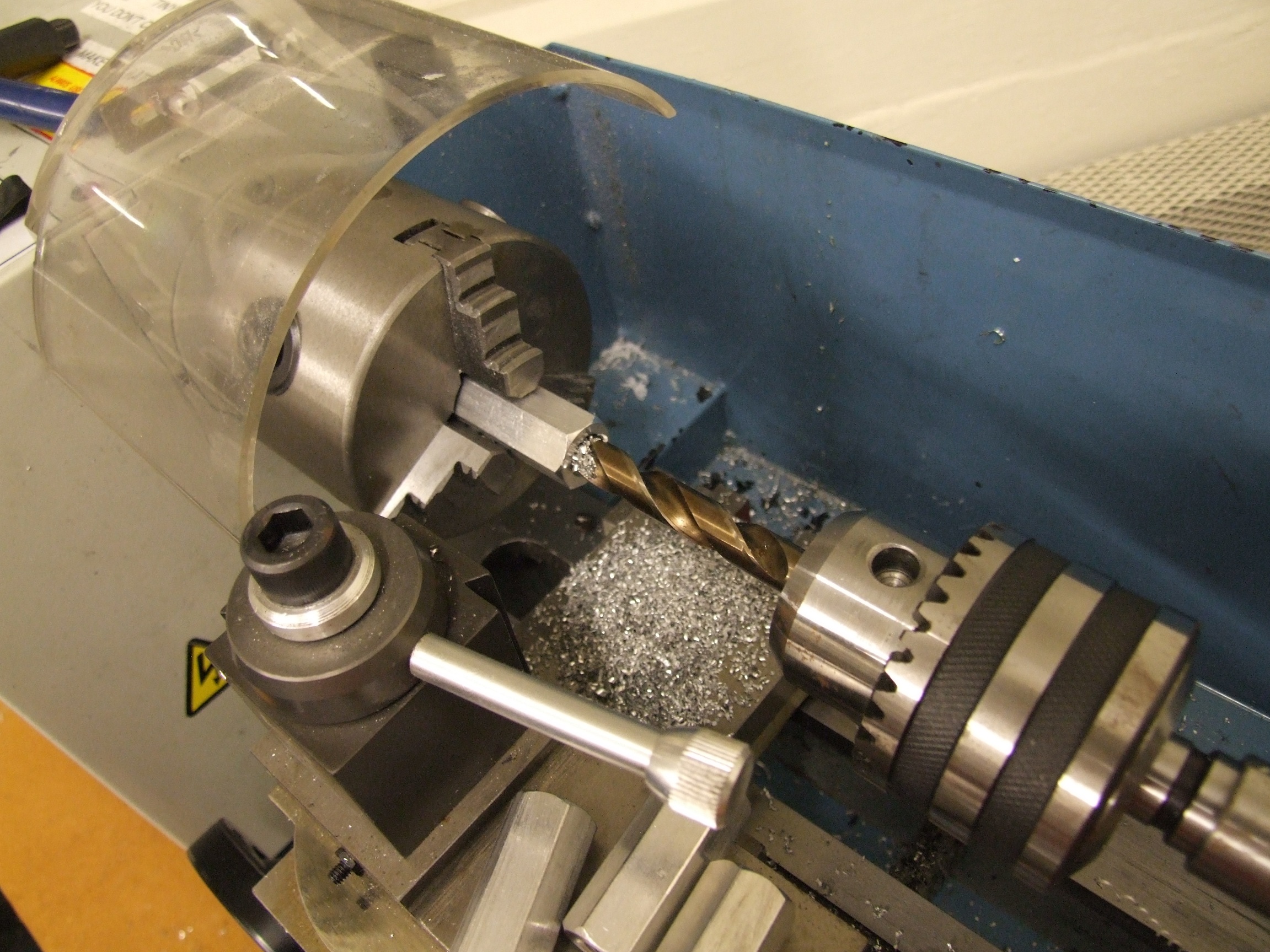
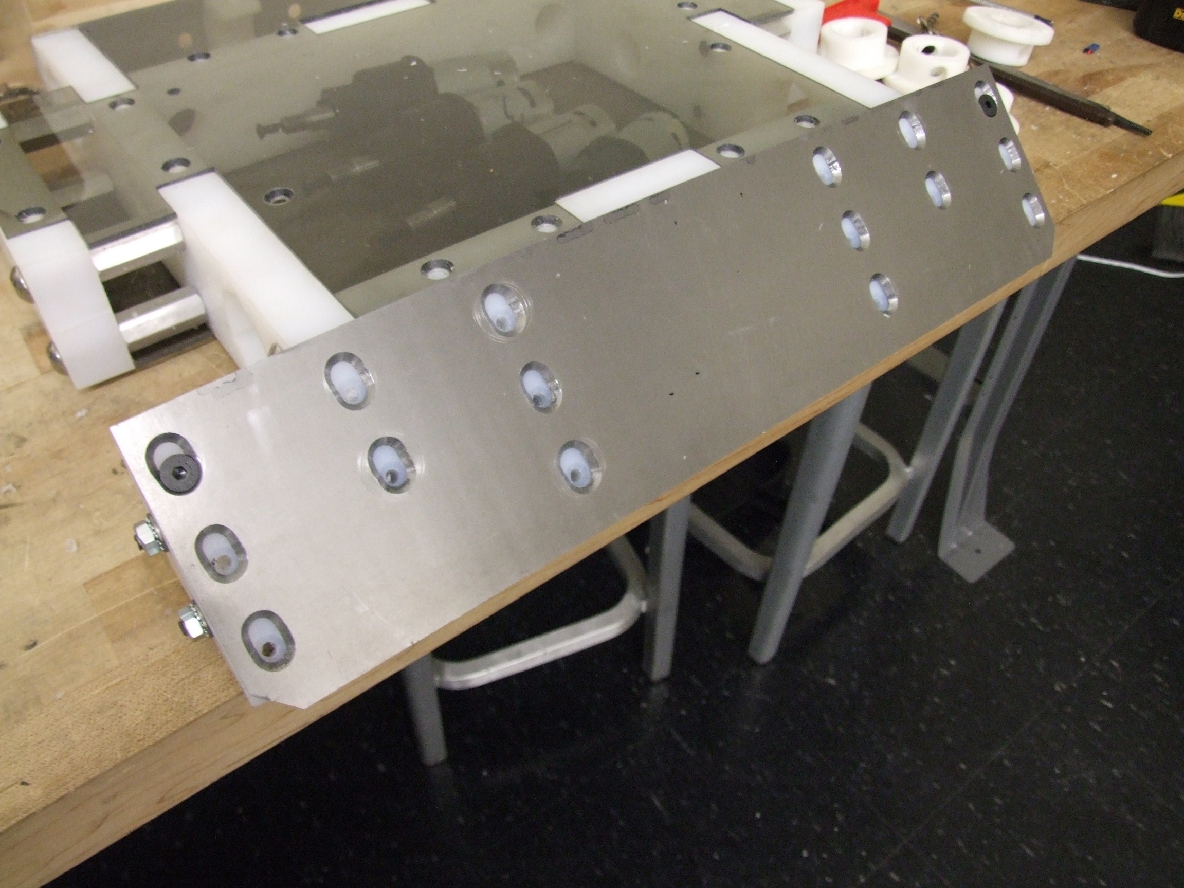
The frame standoffs are stock from McMaster. Now, these things come threaded, but I actually just need spacers (unthreaded, pass-through), so I drilled them out.
It turns out that large standoffs only cost about $1 in quantity. McMaster must have found a cheap supplier for standoffs recently, because I definitely remember almost all of the small ones like 4-40s and 6-32s also costing $1 each or so. But now they seem to hover around 30-40 cents.
This is great, because it means it’s actually far cheaper for me to buy a bag of them as “stock” than to machine them myself. Previously, if I needed a bunch of odd standoffs, I’d machine all of them, which takes alot of time, and I’m sure an industrial manufacturing process can produce more consistent parts than I ever care to.

Because I was able to keep the slots and cutouts, the frame acted as its own machining fixture very well. I clamped the parts to the table and drilled where needed. It was pretty much assembled in situ. All of the fasteners are 3/8″-16 button head cap screws. On the top and bottom, I’m going to have 1/4″-20s because larger screws have impractically large heads to countersink into 1/8″ thick material.
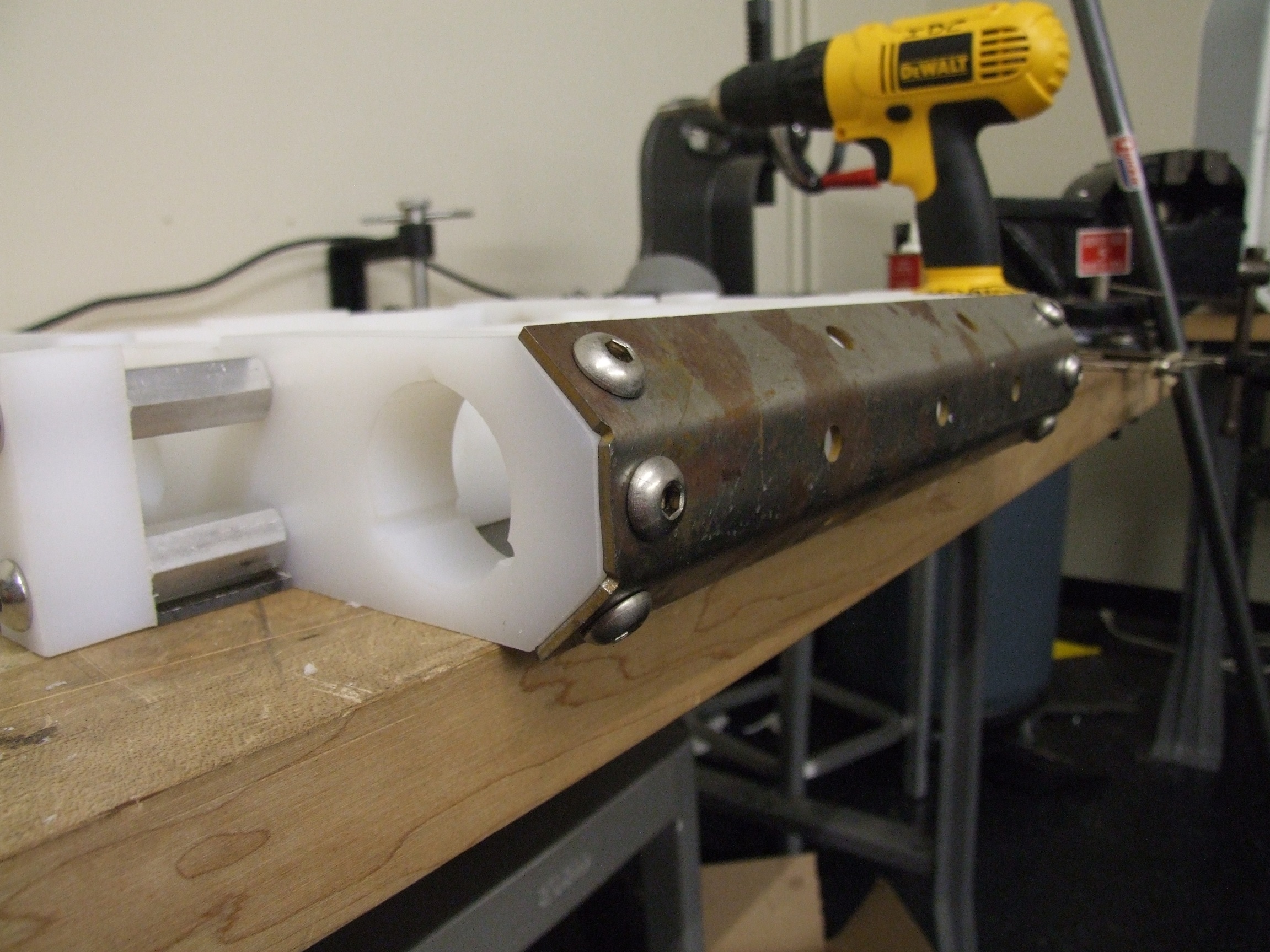
The back plate was clamped in place on the bot first, then the mounting holes drilled and tapped in-place. The steel was very slightly too acute of an angle, but the screw pressure was enough to keep it fully flush with the beveled surfaces. I like how this back plate came out.
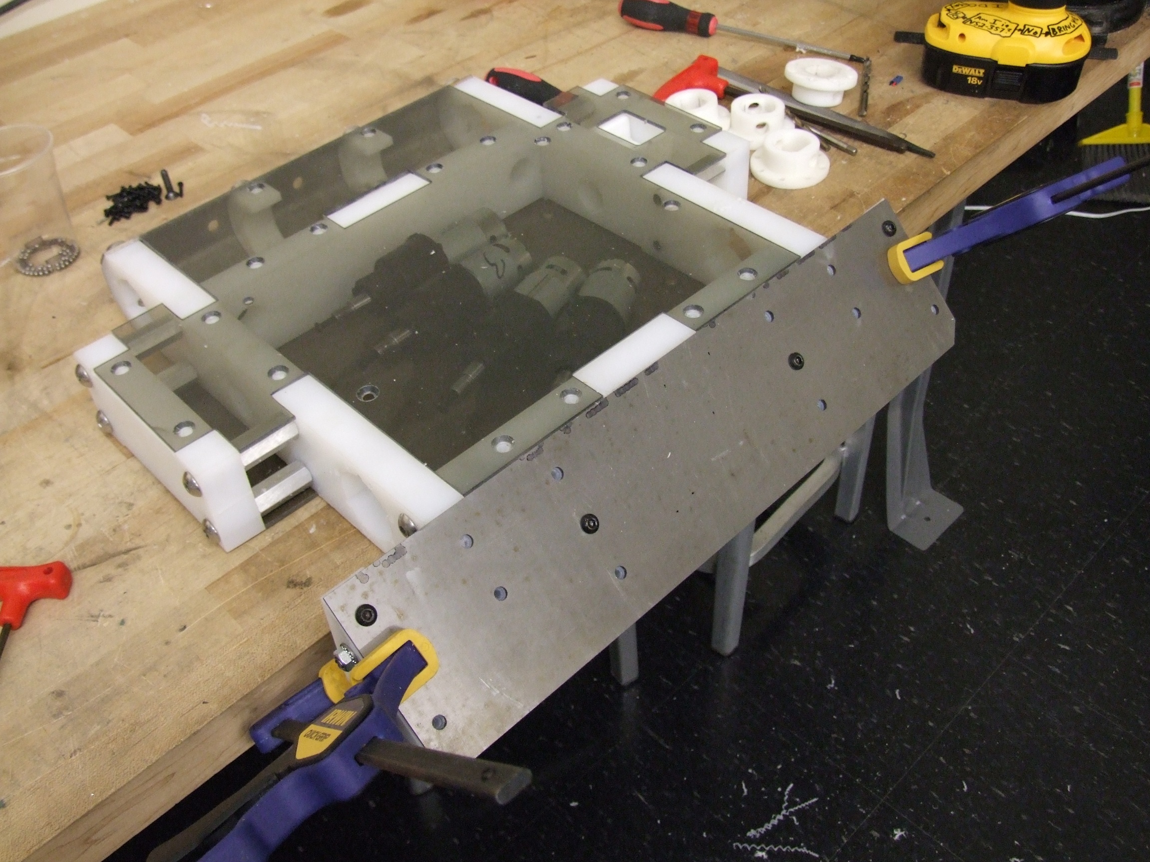
One advantage of keeping with the strict waterjetting diet is that I was able to easily make these ‘form fitting’ mounts for the drills. Granted, 3 holes and a big center bored hole would have gotten me the same.
Because the material is so thick, the entirety of the gearbox is well supported. The motor is actually fixtured from movement on the outside of the frame rails…
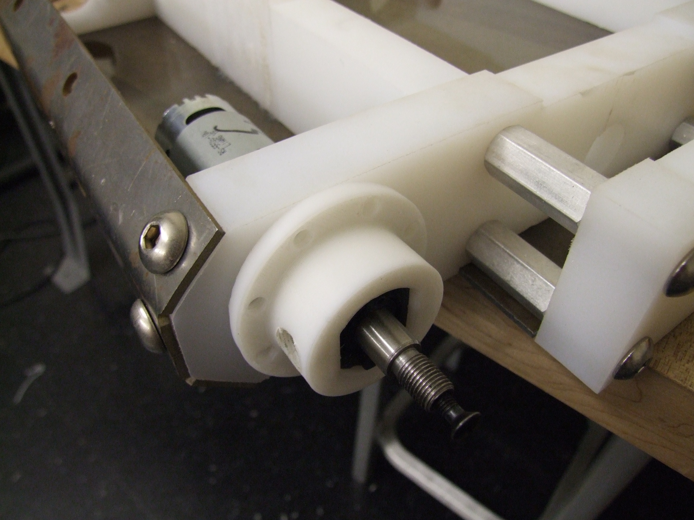
…like so. I’m really hoping these 3D printed ABS hub-things stand up to physical abuse. They’re 100% solid, but ABS is still a pretty soft plastic, especially when laid down in noodle form using the Lab Replicator (because we live in the future now). This let me build the double-D shape of the drill output exactly.
I didn’t actually get to mount the motors permanently – the frame wasn’t done with hole drilling, and I was also missing the correct screws to secure the flange to the frame and those giant set screw things for the motors.
Most of the frame is now completed. The top and bottom plates were also drilled and tapped in-place using the holes in the polycarbonate plates as a template. Afterwards, they were clearance-drilled and countersunk appropriately.
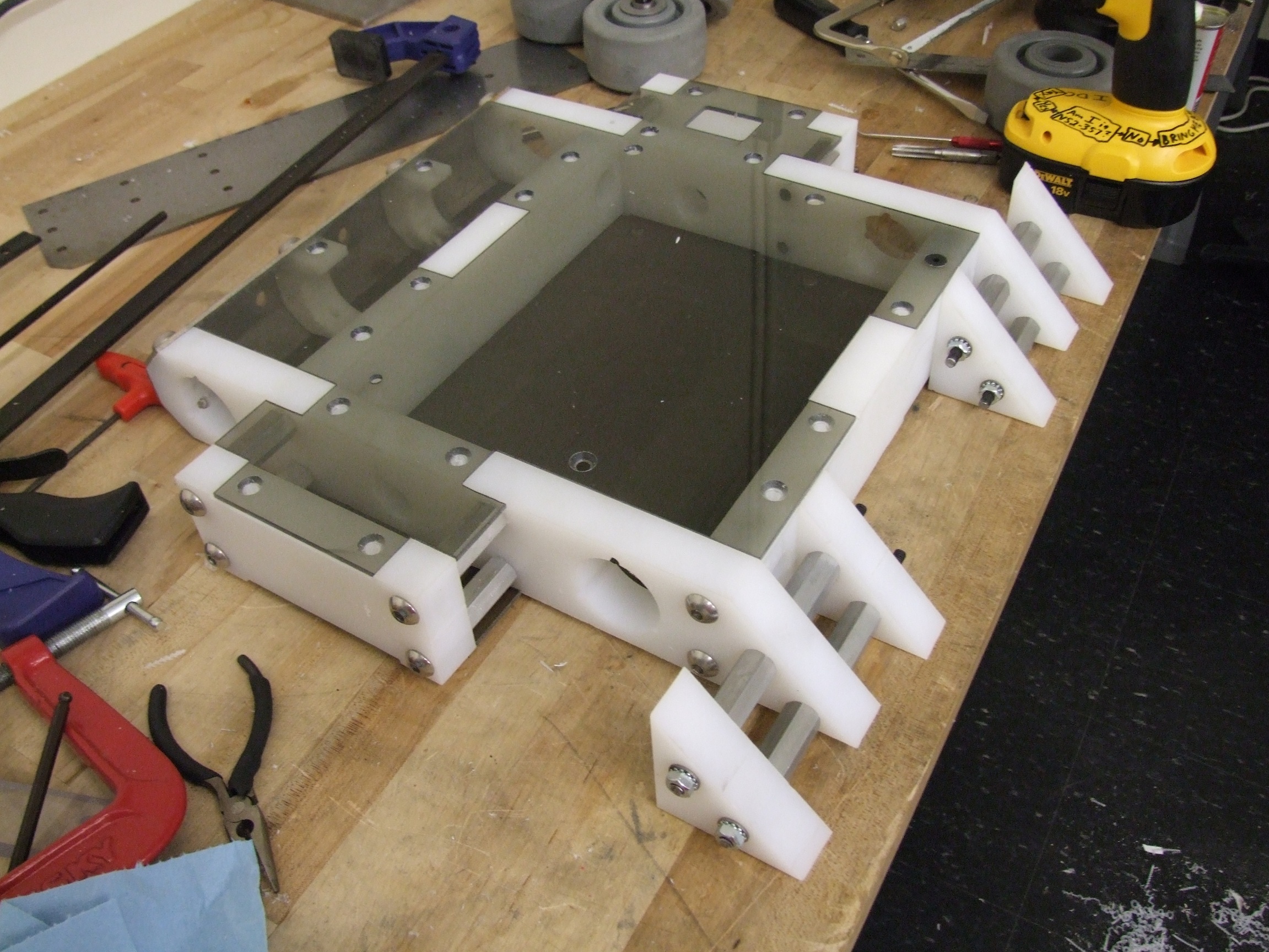
Frame fully assembled now, but without the front wedge holes drilled yet. I was waiting on the correct length 1/4″-20 screws to show up before I mount everything.
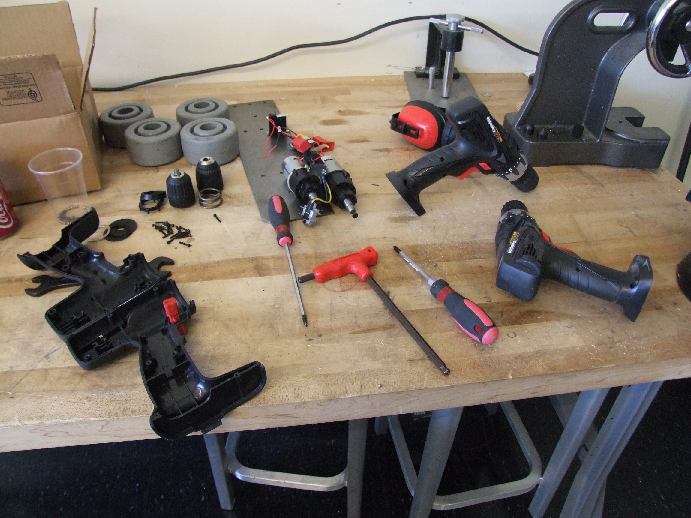
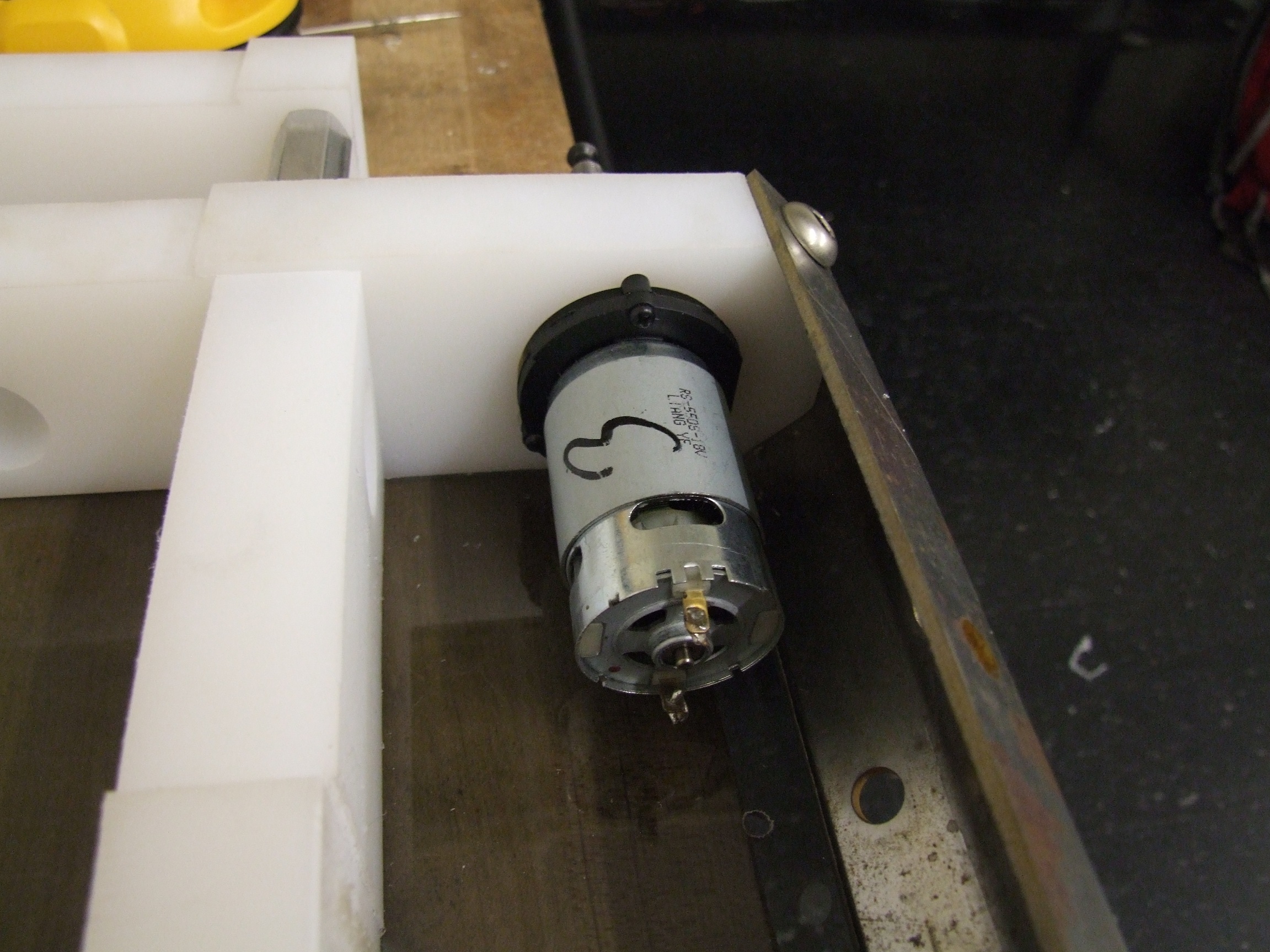
In the mean time, I started dissecting drills. I have, in total, 8 dril….err, drive motors for this thing, and hopefully I don’t go through all of them. These are all Harbor Freight p/n 68239, the latest model of shady 18v drill HF offers. They have a verified 24:1 gearbox, though with a plastic first stage (not necessarily bad, in my opinion).
Even 24:1 is a little high ratiowise for the speeds I want to get to with this thing. The bot will hit about 15mph on 26 volts (8S A123s, 3.2 volts each), which is a little on the slow side for my tastes despite Clocker never hitting over 10-11mph. It is, after all, a 100% drivetrain bot. I’m also uncertain that the drill motors will like such drastic overvolting. That question will be answered concretely once I put this thing on the ground and push some things around.
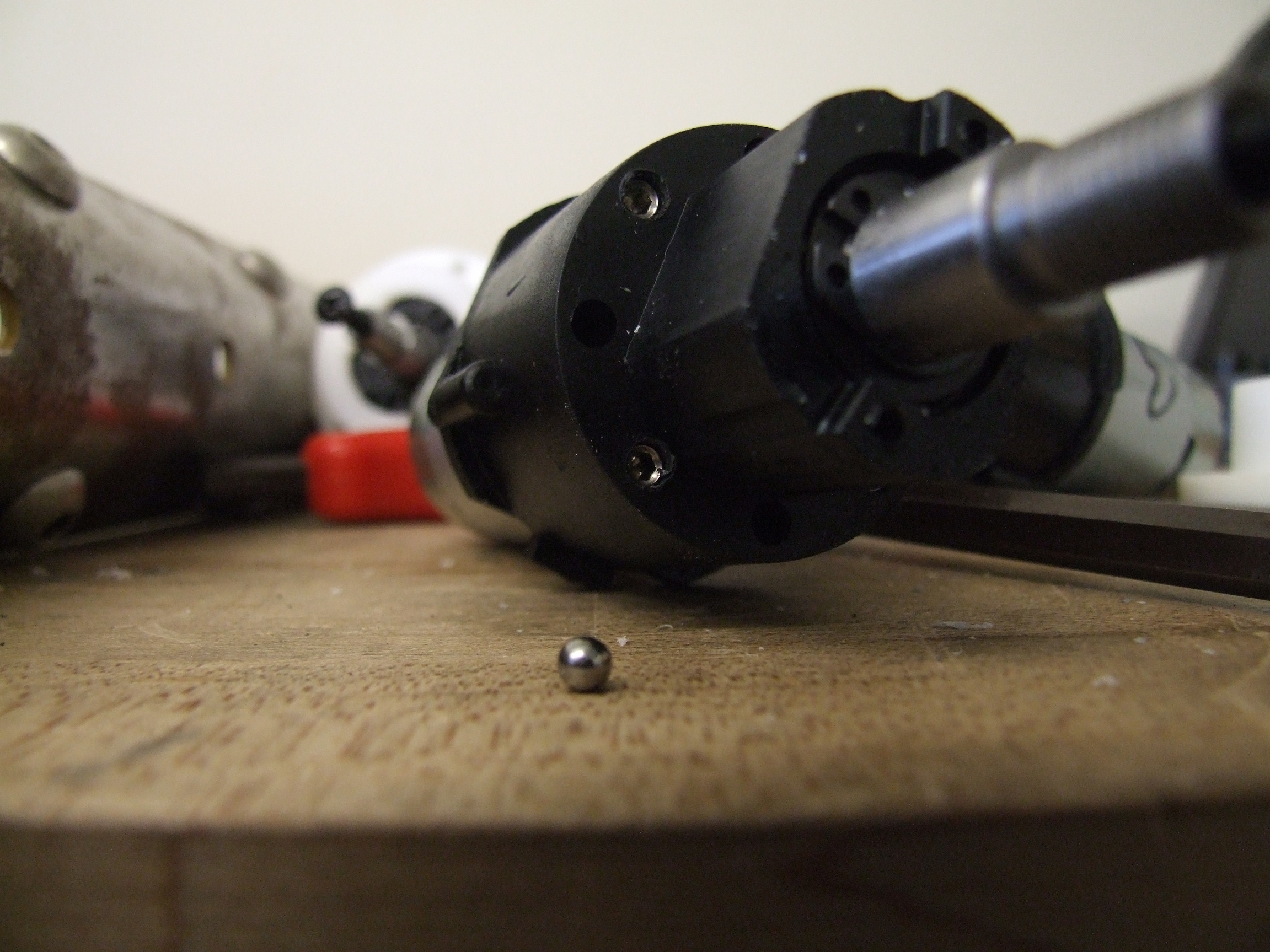
The drills’ torque clutches were hacked in the classical fashion. I used to know many guides on to hack these things, but they were from years ago and many have gone offline as builders retired. Basically, the hole is the perfect size to tap for #10-24 or #10-32. Short set screws are used to entrap the dog clutch element that is the main component of the adjustable torque limiter – without these, the ring gear would just spin freely and no torque can be transmitted to the wheel. Dale has another method of locking the torque clutch which is a bit more compliant.
I decided later to proceed with drilling the wedge mounting holes, since I had a bad idea coming up for the plate itself. The wedge was clamped directly to the frame, aligned horizontally, and the holes drilled and tapped in situ.
The process I’ve been using is first drilling a dimple using a pilot drill of the template hole diameter (in this case, using an F size drill because I designed those holes to clear 1/4″-20 scrws), such that the dimple is reasonably well centered. Next, I switched to the tap drill diameter and let it settle in the dimple, then just freehanded it. Not all the holes are dead square, but that’s just a consequence of free drilling and only practice and experience can get them close.

Alright, so this is the bad idea. Not shown in the robot’s 3D model, but in the works all along, is turning the wedge holes into slots. This would have been a trivial operation if I were actually just slotting, but because bolts protuding from the surface of your wedge is a glaring sign of n00b, I had to make countersunk slots.
It involved a 6-flute metalcutting countersink (no, do not try this with a cheap hardware store 1-flute wood & drywall countersink), lots of cutting oil, and going very slowly. The whole machine would occasionally rumble and generate a small local earthquake every time I began cutting. In the end, countersunk slots!
And they fit!
Well, most of them – there’s at least 2 which I felt were “oversunk” and wouldn’t be as strong as one of proper depth. That’s why there are 16 screws up front, right?
it’s also being screwed into uhmw.
The ride height of the wedge is adjustable from essentially floor-scraping to about 5/16″ up. The D*C arena/stage/combat surface is not guaranteed to be flat anyhow, so this lets me calibrate the height to the stage as needed.

The last operation of the night is coring out the wheels. These are McMaster’s p/n 2243T41, or “McMasterbots” wheels as I call them, 40A durometer donuts of rubber overmolded onto polypropylene hubs.
As shown in the design previously, these are supposed to partially envelop the motor mounts and use them as a rudimentary secondary bearing. Hopefully, this will make the drivetrain nearly indestructable (from axial and radial impacts like being dropped or flipped) because the majority of shock loads will not be transmitted through the gearbox nose.
The machine of choice for this job is hueglathe, the 19″ LeBlond Regal, because its chuck can effortlessly grab the entire wheel.
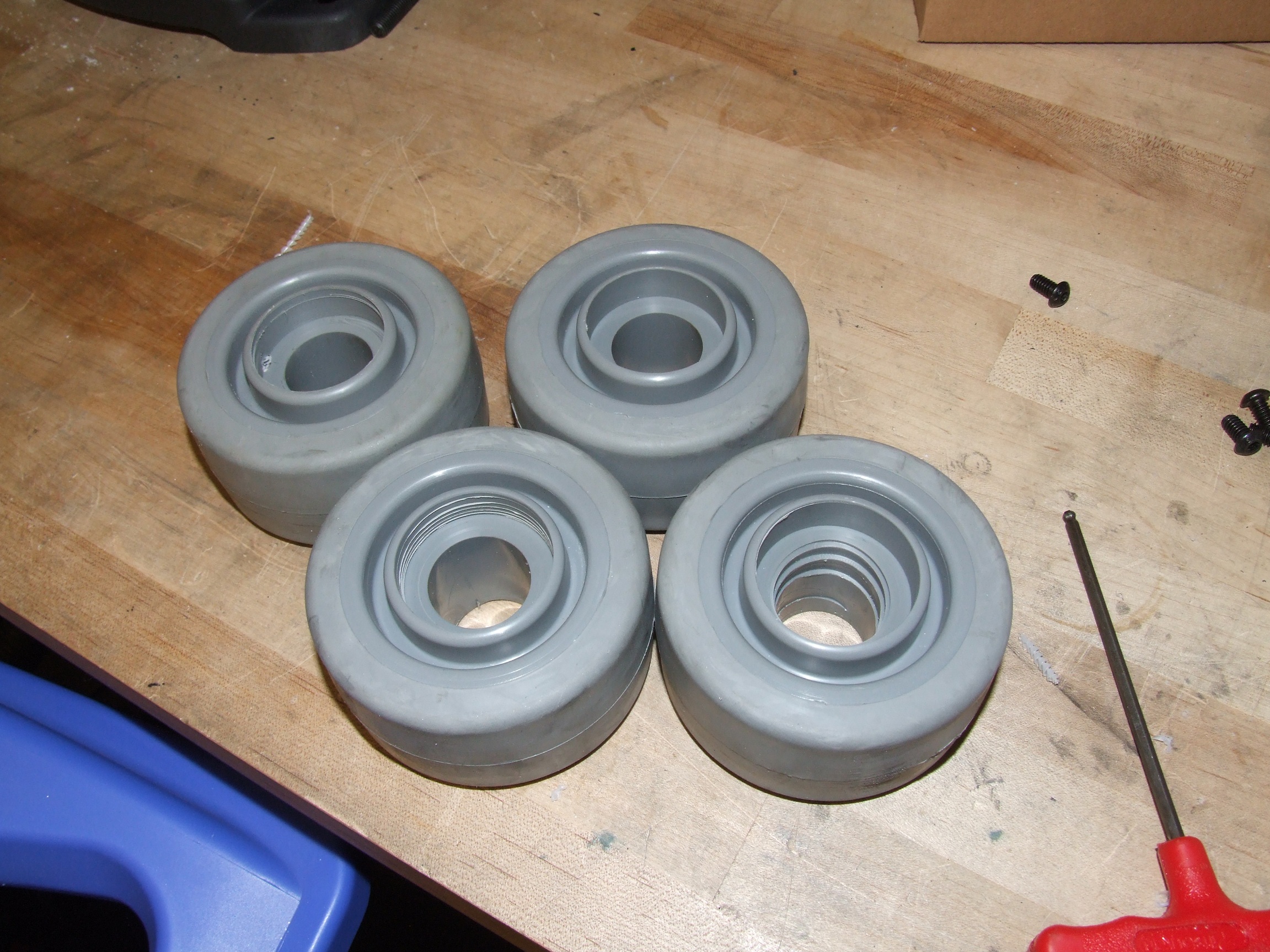
Four wheels cored out to the appropriate depth. Can you guess for which one I forgot to tighten down the chuck before plunging the boring bar into it?
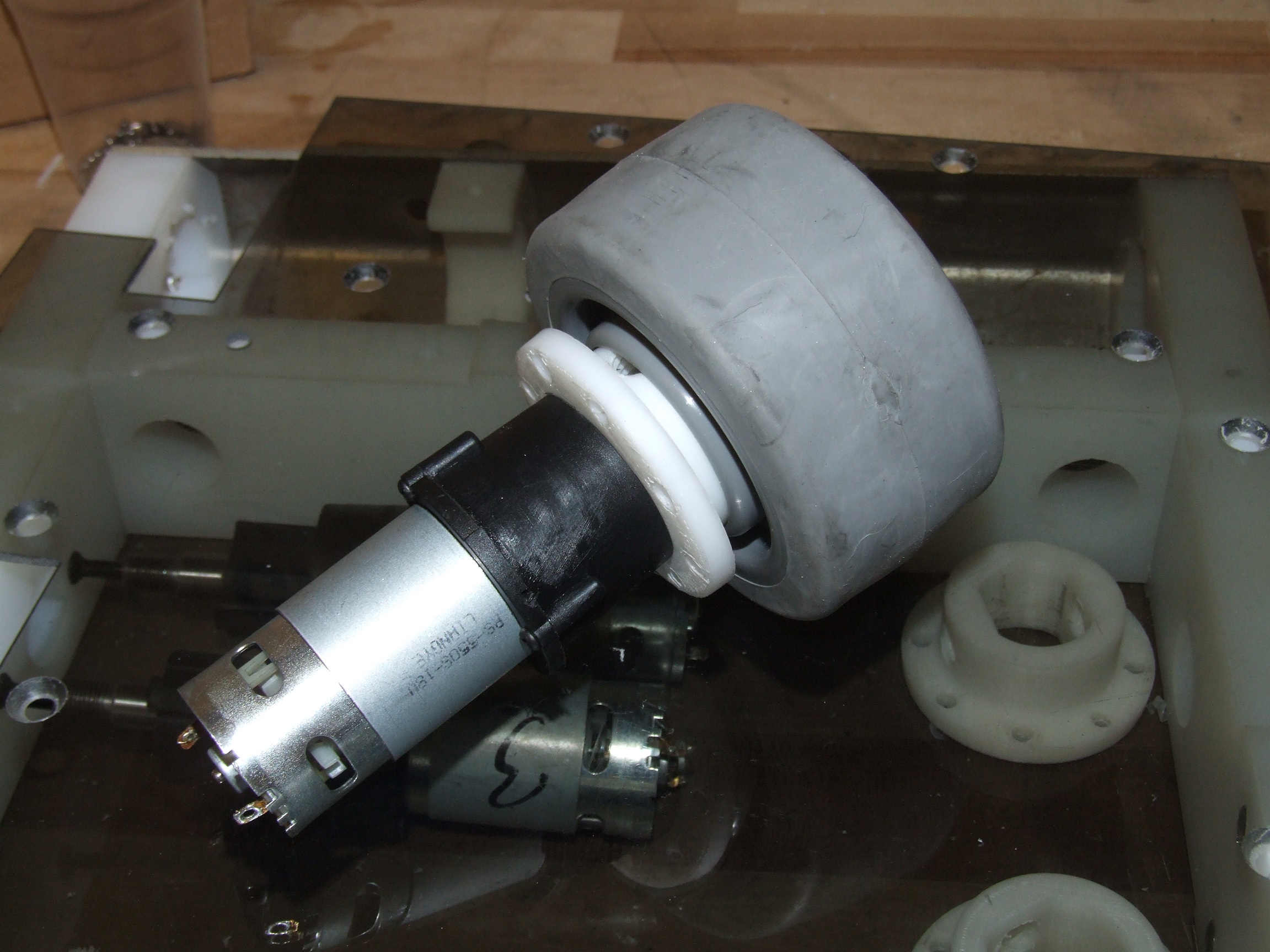
This is how it will go together.
Still to come: Making the wheel hubs, permanently mounting the motor and wheels, and then…
Hmm.
That’s about it. This is a pushybot, after all.


