Big Chuck’s Automotive Blog: The Past Month and Some’s Van Adventures

Welcome to another edition of Big Chuck’s Automotive Blog! This post, being a little long in anticipation, will also be extremely long and full of content. I intend to cover the chronology of a handful of van adventures stretching back to around New Years, after the Great Oil Pan Debacle, and ending most recently with fighting some alternator troubles. Guess what? There’s more bodywork!

Operation: RUSTY MEMORY Part II

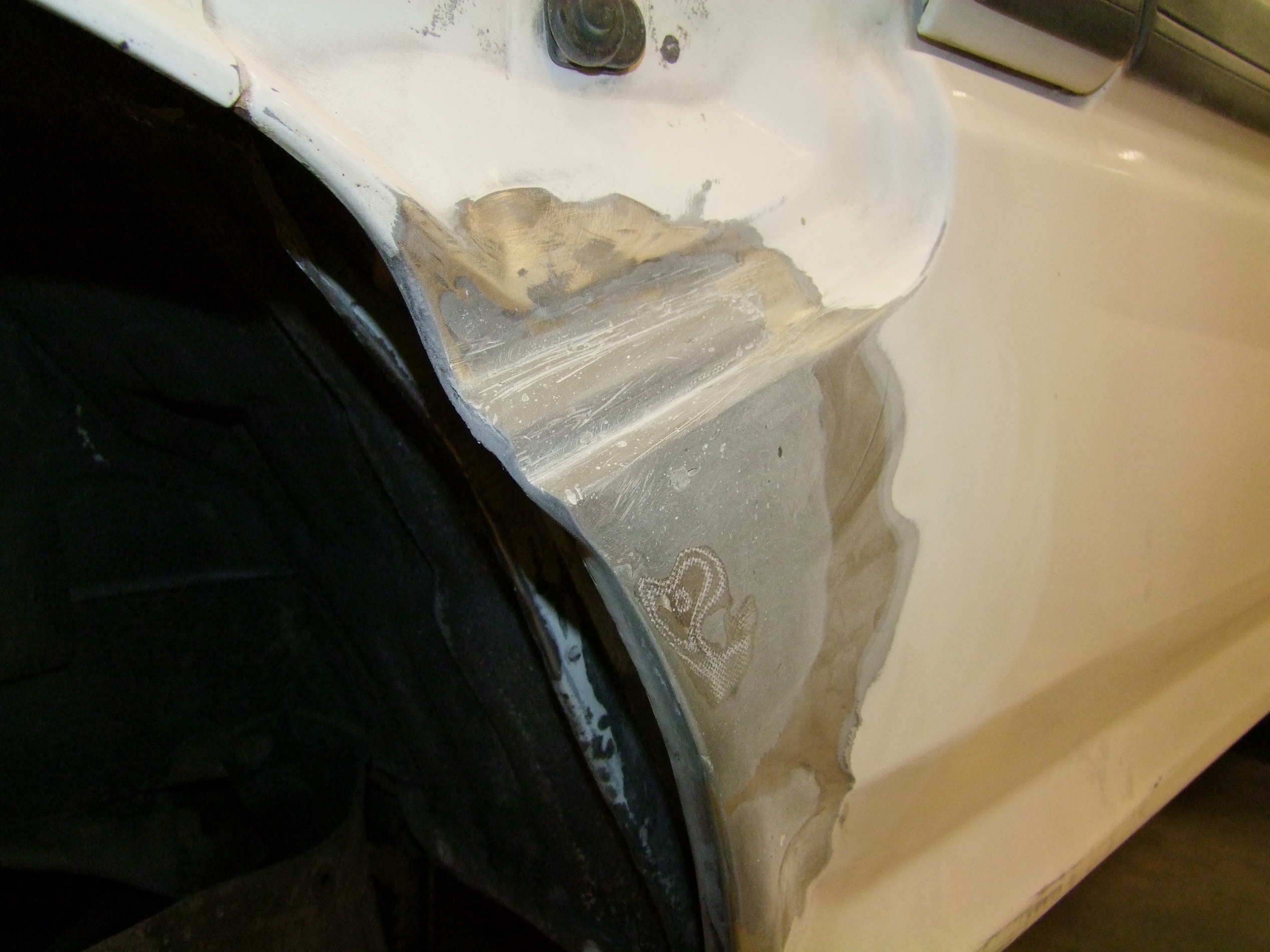
Originally, I posted a picture of the boarding step hole, and was intending to work on that. However, the very weird concave geometry in that area scared me away for the time being. I decided instead to focus on another problem spot – one that, oddly enough, I don’t have a good picture of. The best picture might actually be this, from when I got a new set of winter tires:
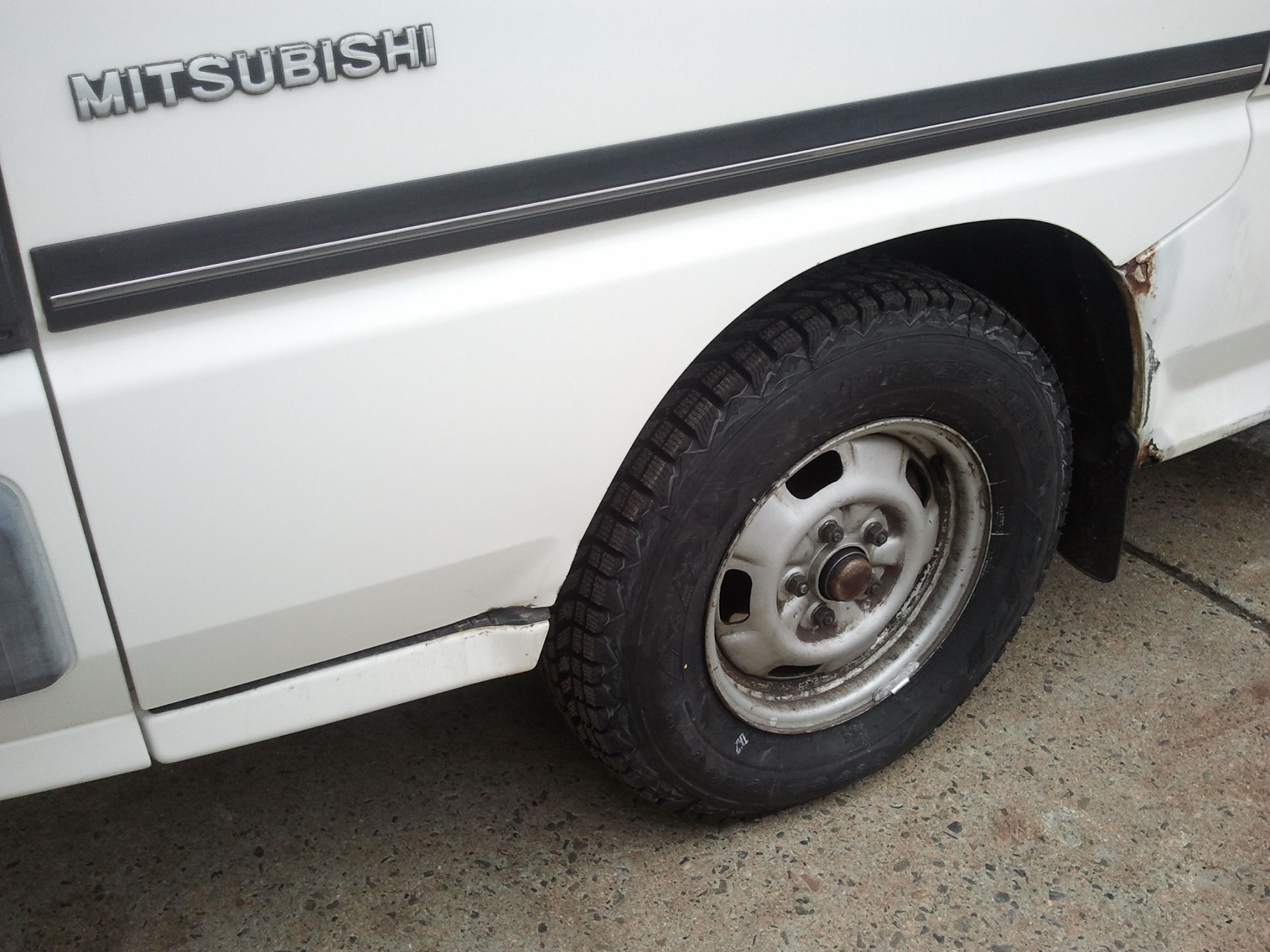
It’s the spot by the rear of the wheelwell, which is also visible in one of the first images.

At first, this spot seemed to be better suited for practicing, since it was primarily convex or flat. I knew that I would be chipping off someone else’s hack to add my own, because the area was clearly made of flaking Bondo and not metal, but I figured it couldn’t be too bad.

Famous last van words.

This spot was different than the hatch and underside which I’ve done in prior posts. First, this is a prominently visible part of the vehicle. Second, through the first two jobs, I’ve become more confident in my “body man” skills. I planned this job to take more time and detail than the previous ones. Hell, I even asked the Solar Car and FSAE teams if I could hog the garage for the whole weekend plus some, instead of just pulling in, beasting it, and slinking away.

So here I am in the auto shop one weekend with an air saw and Dremel with a carbide burr, shaving a yak.

Step one was, as usual, discovery and exploration. I started by knocking that corner in and breaking it up into dust; the old adage “by the time you see rust, it’s too late” holds. Next, I carved away most of the steel around where rust gave way to ductile metal out to about half an inch away.

Notice the green coating inside – that’s a dose of “rust encapsulation” compound that I bought on recommendation. About a week before I broke into this region, I gave a thorough covering through the holes in the bottom. Hey, at least they were good for something. I was told that this would aid in holding off worse corrosion and give me some more months to get to repairs.

Only the outside skin has been carved in this picture – the inside wheelwell area is still in the process of discovery. Check out that thin sliver remaining of the outer skin – that was kept so I had an idea of the lines to follow.
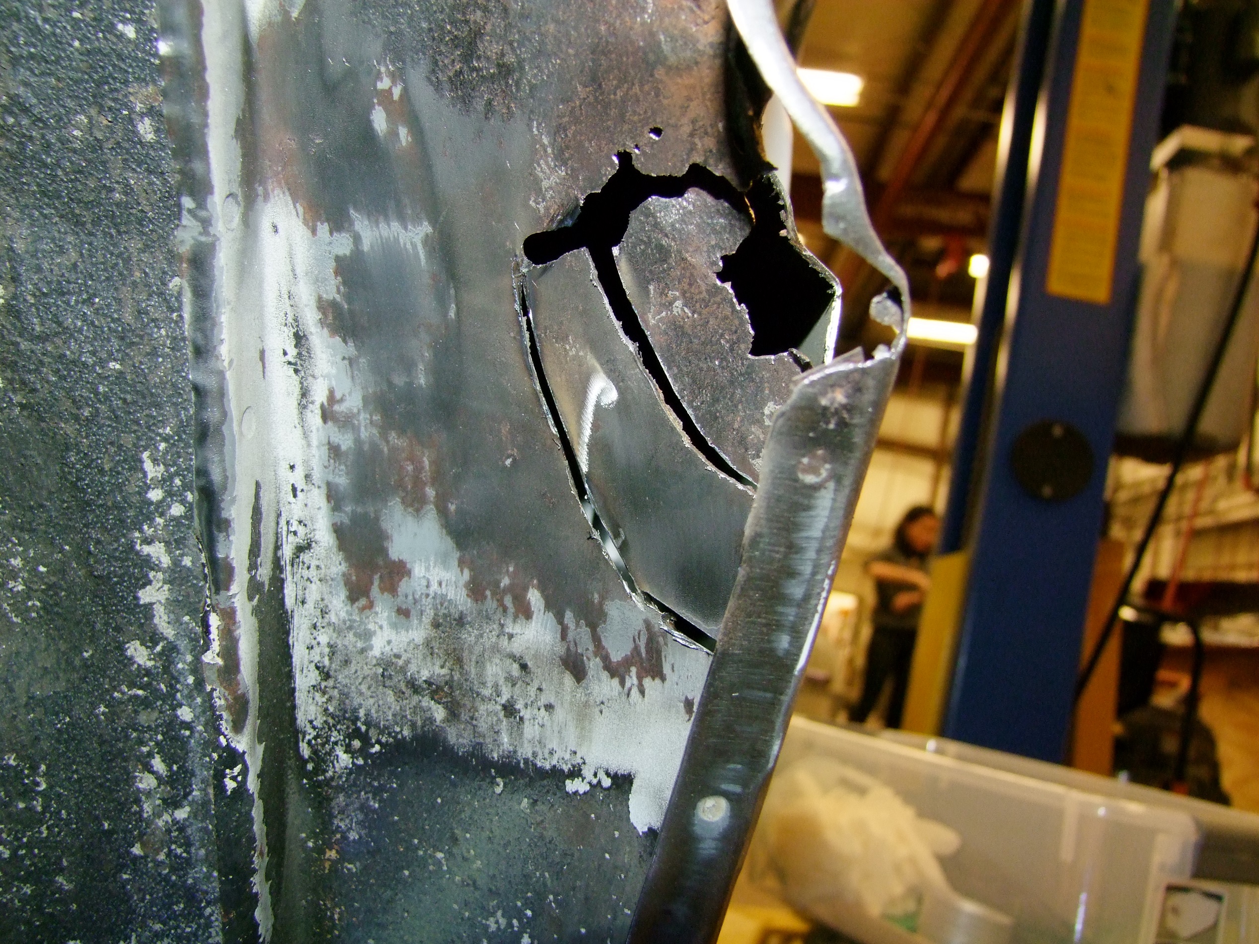
Taking sweeping cuts with the Dremel on the inside now.
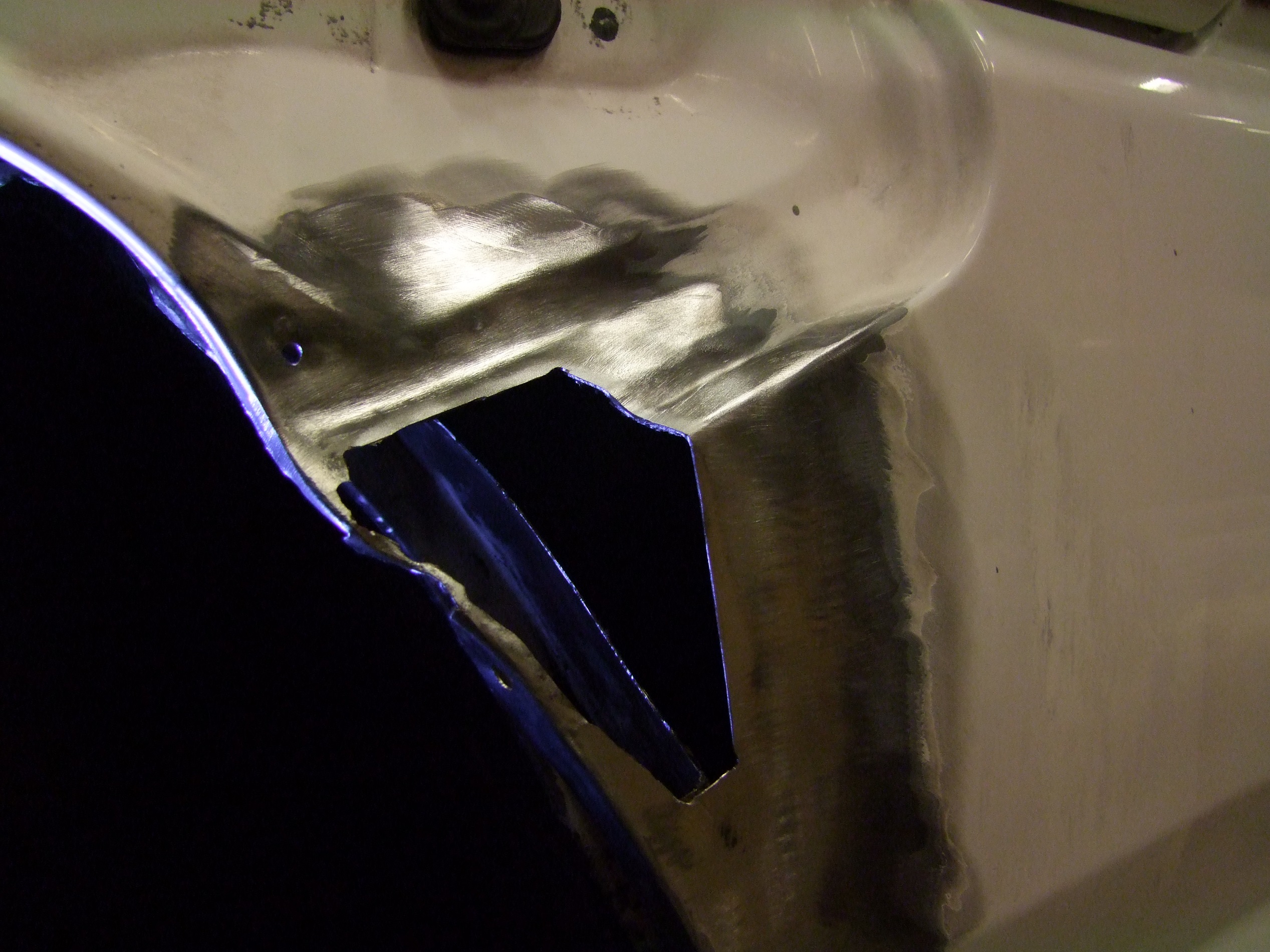
The whole area cleaned up, corners filleted, and more paint sanded off in preparation for fiber layup.

The final pile of excised cancer, plus a mass grave of deceased Dremel wheels.

My usual tactic is three layers of fiberglass cloth on the outside only, but that would have caused too much protrusion here. Instead, I only did two on the outside…
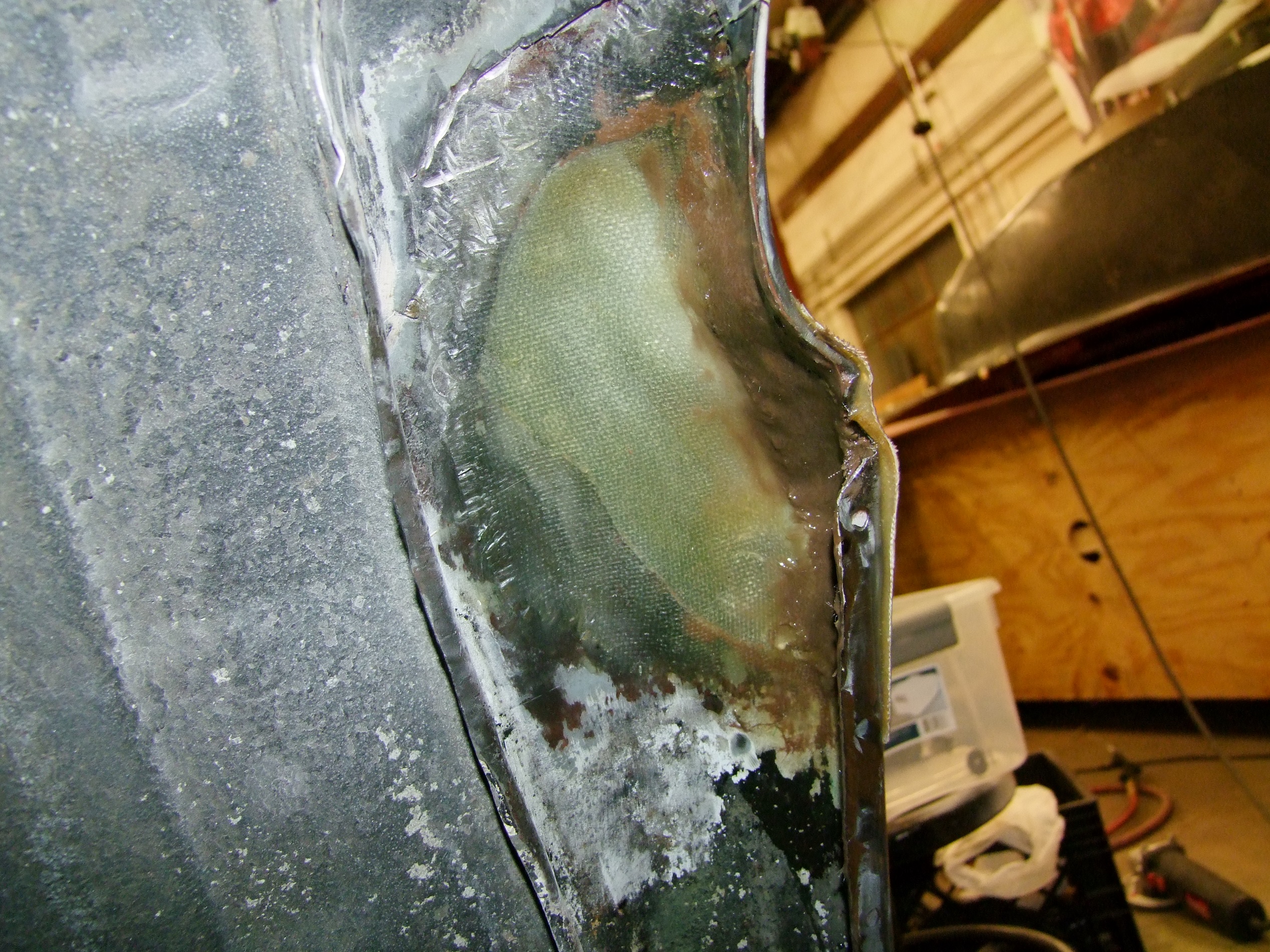
…and two from the inside, reaching through the wheelwell hole. I then closed the area off with two layers in the wheelwell area.

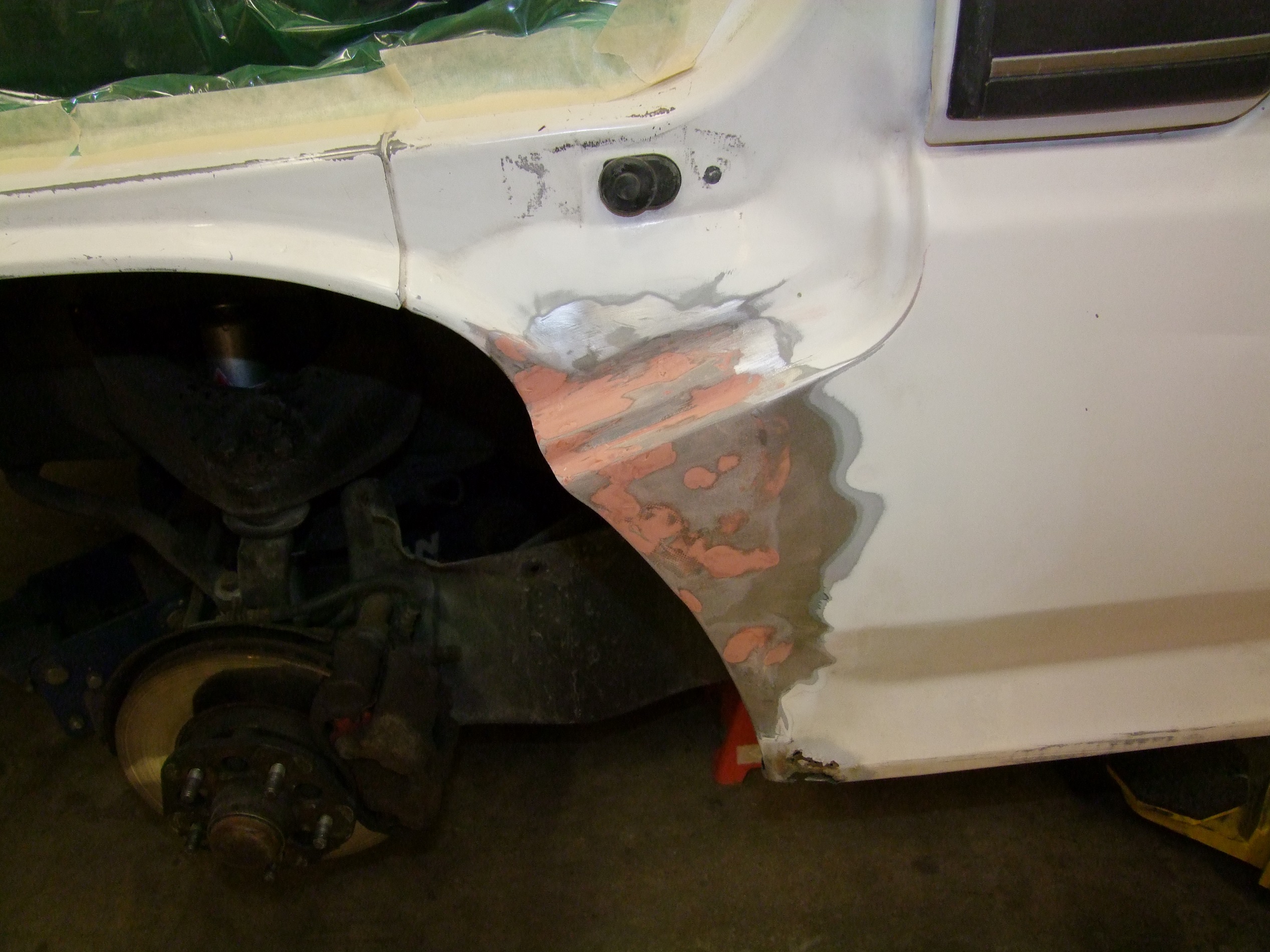
The large brown patch in both preceding images is a berm made of fiberglass-filled Bondo I picked up because I was advised it has much higher strength than the regular pasty stuff. I then mixed in some short-strand glass filler from the Solar Car team (basically, the whole thing will eventually turn into a solar car).

The finished region is probably the strongest point on the whole body. I’ve heard of people mixing their own glass filler with normal pasty Bondo before, but who’s gone even harder and done glass-filled-glass-filled-filler?

Night #1 was spent letting the whole goopy pile cure under the influence of a work lamp.

The next day was devoted to finishing and sanding. First, some of the excess glass and filler had to be removed from the wheelwell area behind the folded flange, but I couldn’t get in there with anything facing the right way. Solution?
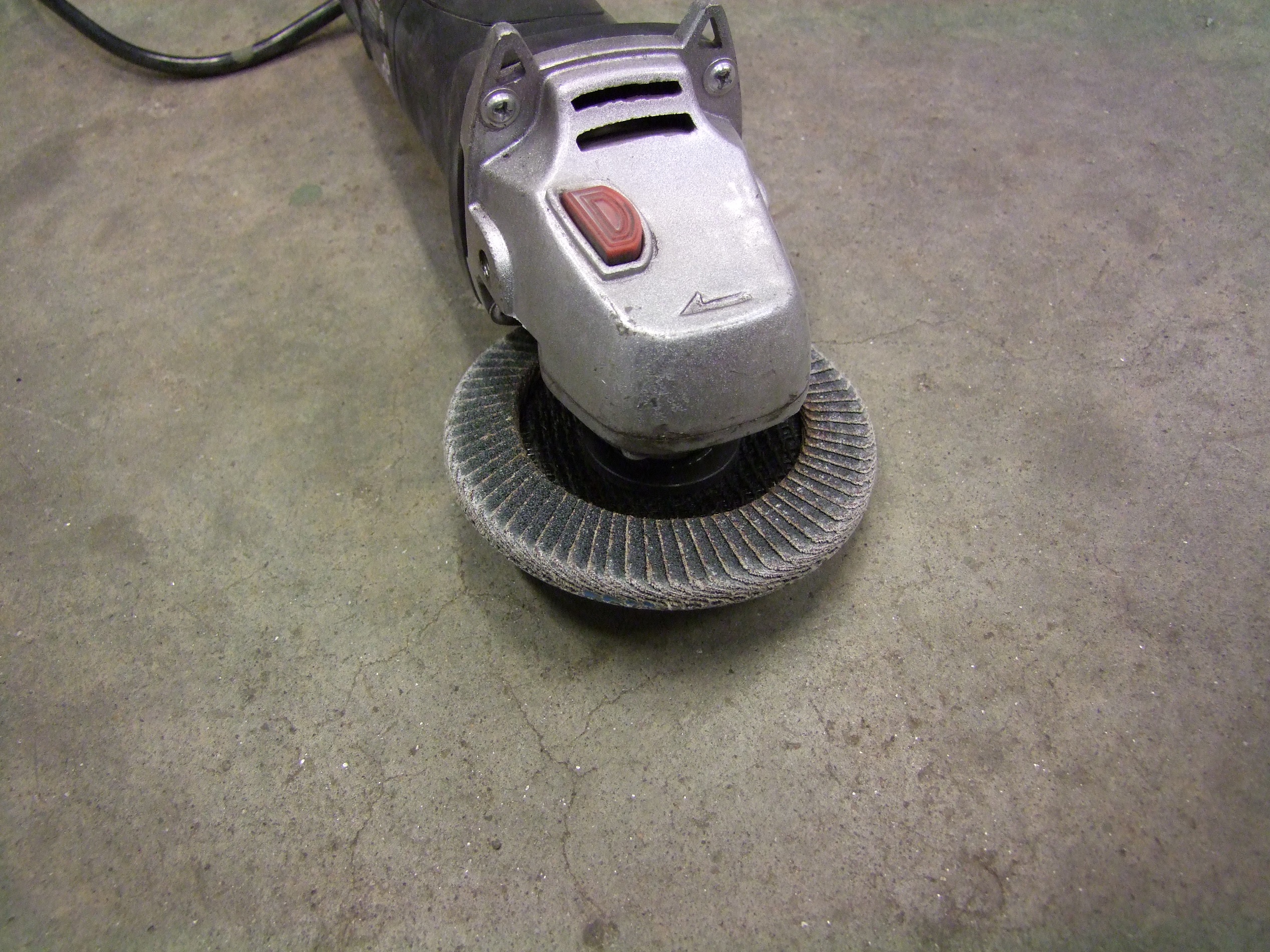
Face it the wrong way. This upside down flap disc was a shoot-around-the-corner method that I made accidentally at first but realized the brilliance. With light pressure, this was actually working beautifully.
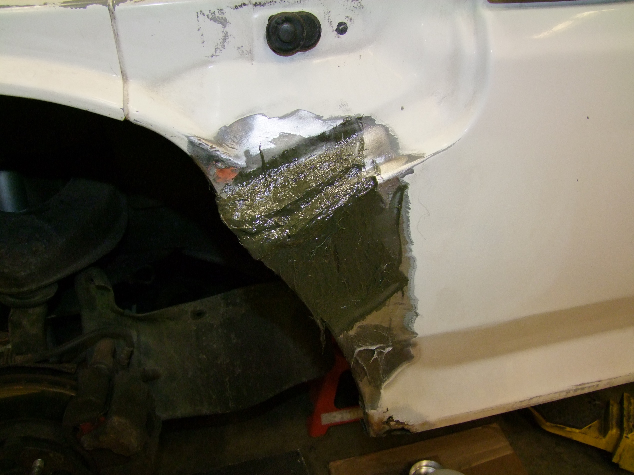
After initial sanding and cleaning, this is Bondo layer 1. I continued using the fibery stuff, but without additional fiber. I do like this substance a lot, but it IS substantially more difficult to mix and apply because of its tendency to behave like trying to fork spaghetti out of a serving dish – some of it wants to come along, some of it doesn’t, and you end up making a drooly mess. It was easier to mix small wads, grab the whole wad, and smear it all over the place (rubber gloves are basically mandatory here).

In the middle of hand and power sanding the mountaintops down. At this point, I was still going for rough fit.

Hmm, not quite there yet. I promised myself I would take time and put energy into making this corner look nice, so…
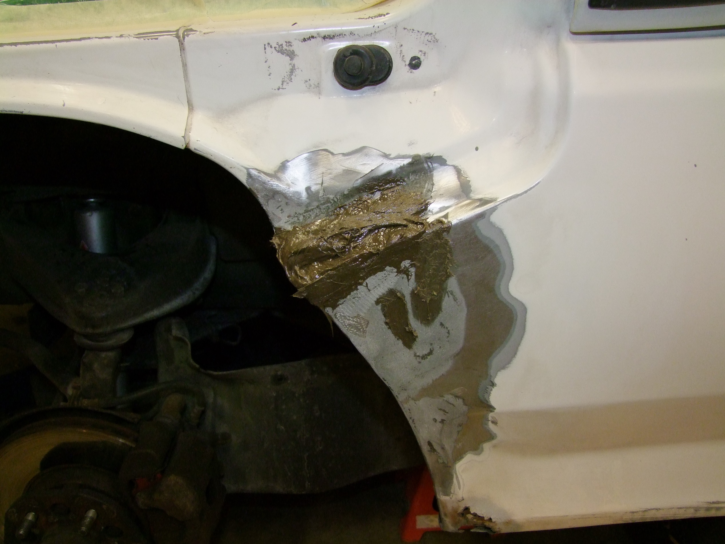
Layer two time! One thing I learned about body filling is that slathering is essential, compared to being conservative. You slather and then shape & sand away, and so the method leaves you the maximum possible error budget to make adjustments. I’ve been too stingy before, which pains me greatly to admit.

This time, in order to have more control of the shape, I only used a power palm sander briefly to knock down the peaks, then used a flexible body file to d….

Wait, no, I didn’t have a body file. I used a short rough D-profile wood file here. This stuff sculpts easily, and the process did not take as long as I imagined.

The other side, which doesn’t have damage in this region, was used for reference. This is also another reason why I shyed away from the step holes for now: No reference, because both sides have holes.
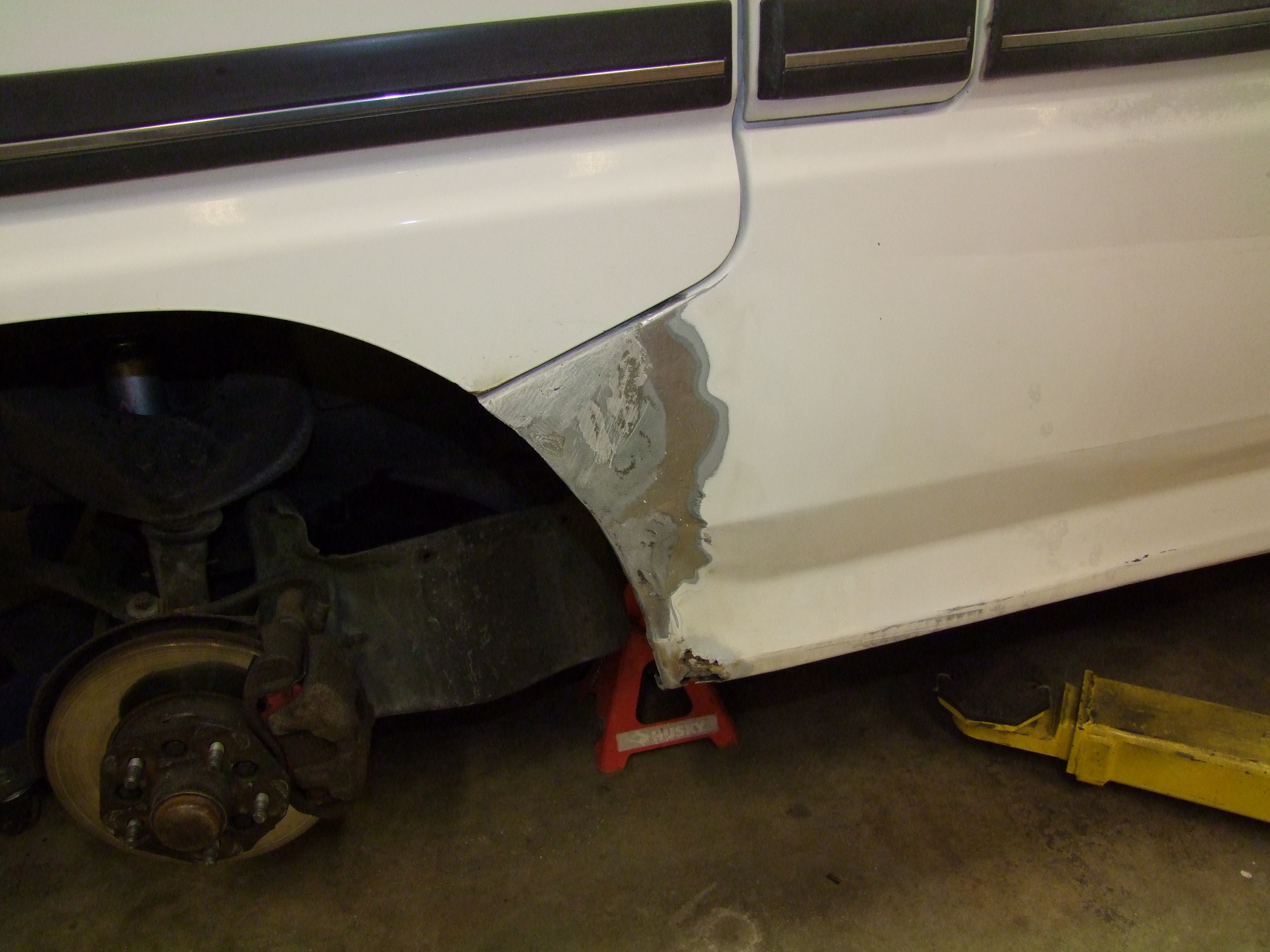
Looking way better now – this was near the end of the rough shaping process.
I moved onto fine finishing with manual sanding. This time, I had 80, 240, and 360 grit sandpapers (guess who I stole it from….) and went progressively finer as I converged on the shape. Serious body guys would go even finer.
After I was satisfied with the outline, I used “spot putty” compound to cover minor divots. There were multiple passes of this stuff too – apply and smooth, come back in half an hour to sand gently, repeat. It seems to be nail polish filled with the same mineral fillers that make up Bondo.

In fact, that must be how it was invented.
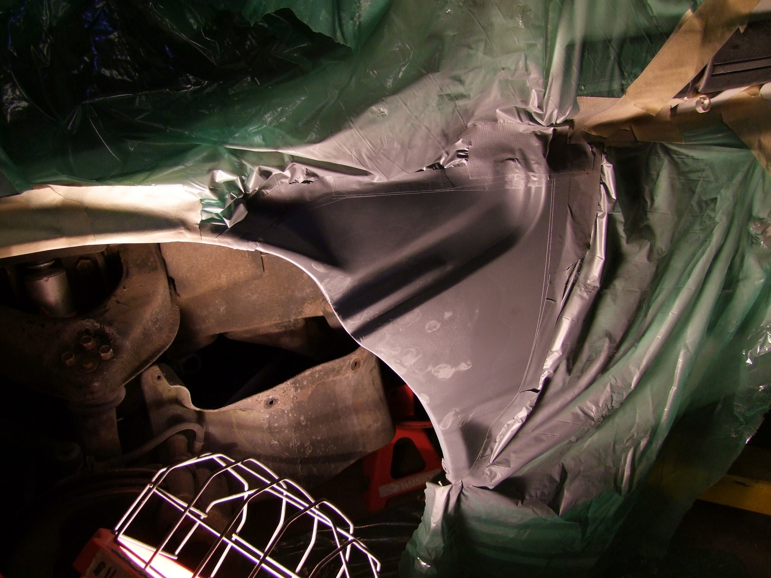
After that ordeal, it was time to start painting. First, I rough-sanded and cleaned an area substantially outside the boundaries of the repair for the new primer to stick to. I used auto store spraypaint primer – nothing special. It was applied in several light coats – I’m getting way better at making spraypaint not run.

The next day, it was time for several body color and clear coats. After the first white coat, I took away most of the masking plastic and let it “blend” the surrounding area, which got a quick hit with left over 360 grit beforehand. No actual mechanical polishing blending was done, it was all just technically overspray. Luckily, white is a hard color to fuck up. You can discern the color difference if you’re looking for it, but I’m again counting on the fact that 99.7% of everyone will not know I am a fake body guy.

The interior of the wheelwell got the Slather Policy. I cleaned and painted this area in the same passes as the exterior, but did not care where it ended up. In fact, the more overlap, the better!

It was finished off with a few coats of spray-on underbody paint.

So there we go. This took from Friday evening until Monday afternoon – the first night was dedicated to glass curing, the second to let the filler layers cure, and the third was in the middle between primer and top coats.

With this experimental application of glass-filled-glass-filled Bondo being successful, I think I’ve formulated a plot for the wheelwell area. Cut away what I can, make a ‘backing’ glass layer in the wheelwell itself (which nobody will look at), then fill the whole area with this concoction and sculpt to shape, following with a top glass layer. I’m interested in reading up on how to deal with concave areas, since you can’t really reach a file or similar into a corner.

Operation: ALTERNATIVE SOLUTION

As mentioned during the Week of Motorama Hell, on the Monday of the competition week, the (probably original) alternator stopped alternating at some point. In this nondescript picture of the front of the engine, it’s the blob of grunge with a pulley on it to the lower left.

In fact, it probably gave out over the weekend, but I only noticed on Monday night when hey, all my lights are really dim and stuff and it’s kind of running like shit since reserve charge on the battery is enough to scoot around town getting parts for a few hours. I’m amazed at just how many parts on this thing were within 10,000 miles of peacing out. Like small prey rodents, reliability engineered machines tend to hide illnesses until there is no other choice.

Well, there was not much I could do but buy a replacement and get it shipped fast. I went the Rock Auto route, because all of the area auto stores had to special order this part anyway.  Since the vehicle hasn’t exhibited any electrical trouble up until that point, I figured the alternator just finally ran out of brushes. Having taken apart a few in the recent past to investigate using them as wound-field AC motors, I know they have brushes, and I also know that brushes like to wear out over time, so….

Anyways, the alternator wasn’t hard to get to. What I’ve learned is that there are often two ways of removing a part – following the carefully laid out instructions in the service manual and disassembling the entire vehicle, or just forcefully shoving my arm into a nether region with a mini-ratchet and accepting that I’m going to leave some blood and skin on something. I actually prefer the latter  because I can see the screw from right here, dammit!.

(Note: the previous sentence was a dramatization; only small scrapes were suffered from being shoulder deep in the cooling fan, power steering pump, and radiator)

So I’ve gotten the tensioner loosened and the pivot bolt thing out and now it’s time to unbolt the B+ terminal and…

…it shears right off. Great. At least I can solder.

Getting this thing out was a careful multi-point reorientation job while slowly pulling up. The gap next to the exhaust manifold cover and the lower wiring harness seen was its escape path – it just barely fit.  One… alternative… path is to take off the oil filter and drop it out underneath. The official by-the-book replacement is 75% of the way to a new timing belt.
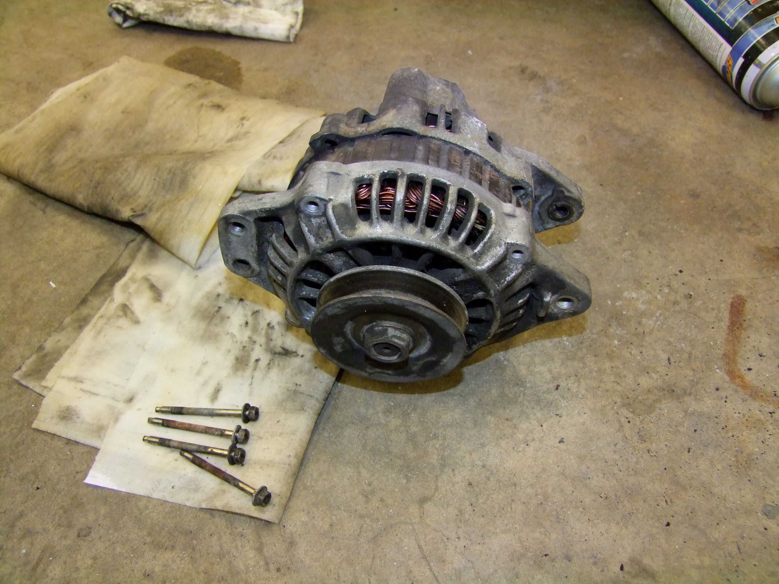
This thing is looking pretty ragged. Because it was Motorama Thursday at this point, and my package was nailbightingly undelivered, I decided to try rebuilding it with scooter motor brushes. I hold to my statement that Mikuvan will soon become 1. a solar car, or alternatively, 2. a small, cheap Chinese electric scooter.

I rebuilt the air conditioner blower motor with harvested scooter motor brushes. It’s still working.

So, how do I take the alternator apart? Why, the old “Pry with screwdriver”. In the electrical service manual, it literally tells me to stick a plain screwdriver between the bracket and stator and pry. There’s even little slots in the laminations to jam said screwdriver into.
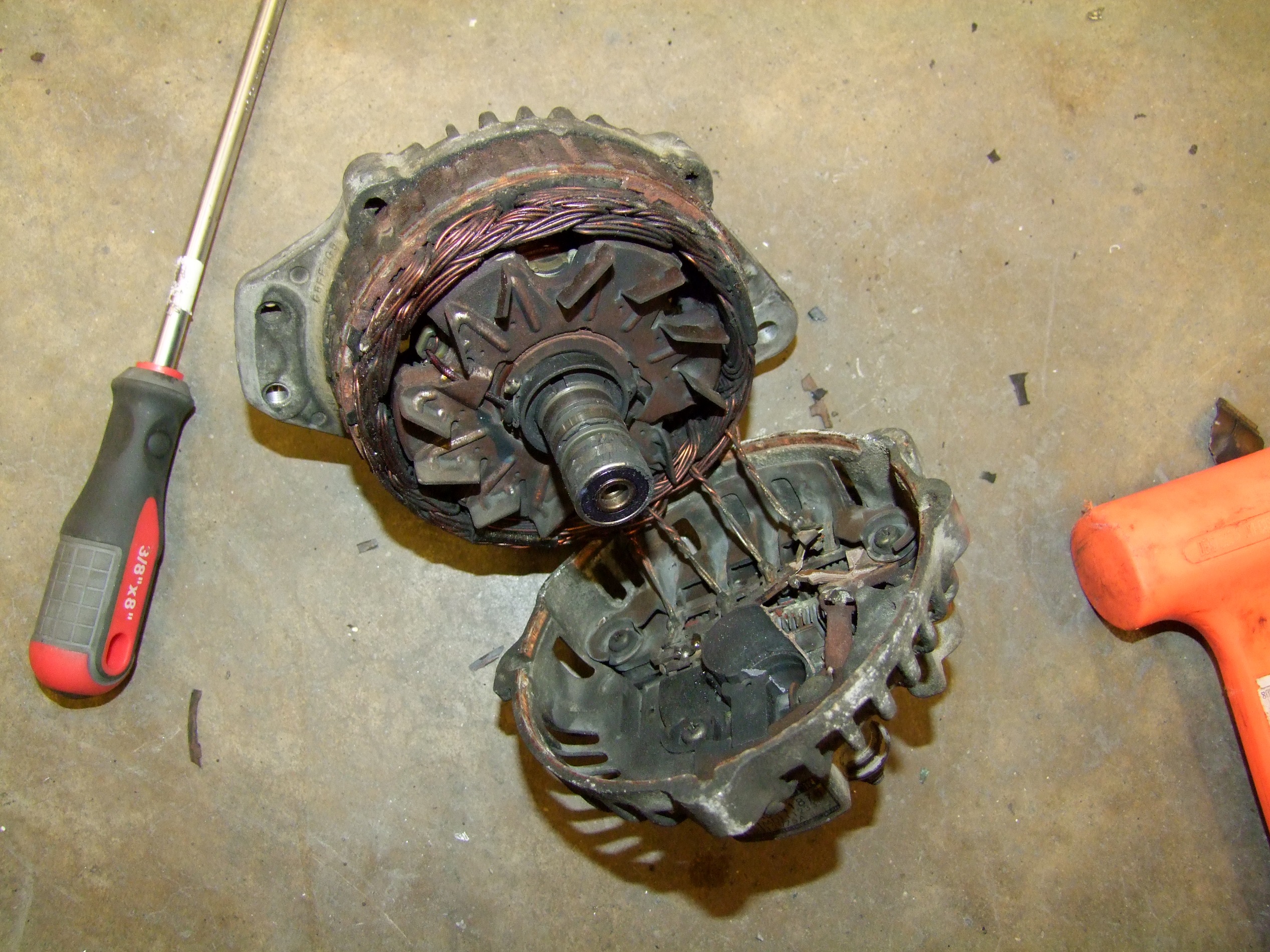
Haven’t I learned anything from the last time something told me to “Pry with screwdriver“? It must be the Harbor Freight screwdriver.

Alright, now that I’ve successfully torn the diodes off, time to sit and wait for Fedex. At the very least, I confirmed that it did run out of brushes – they barely moved when the rotor was taken out, having reached the end of their spring travel.

(I now know that I was supposed to pry the front bracket off, which would have caused the [pulley, front bracket, rotor] assembly to come apart from the [stator, rectifier, brush holder, rear bracket] assembly cleanly. But there were no screwdriver slots there!)
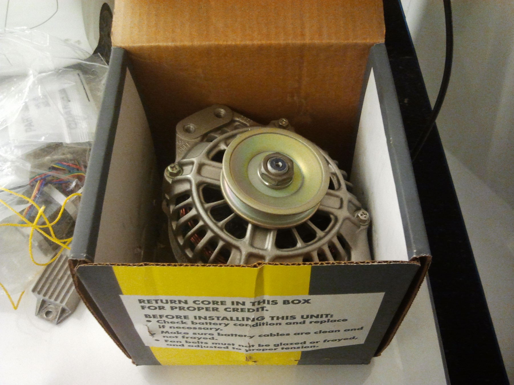
Fortunately, Fedex delivered at 7:30pm on Thursday. In the days prior, we were hit with a few more inches of snow, so everything was backlogged a little. I was fresh off destroying the old alternator, and so was getting ready to call the car rental place by this point.

Hey, you guys sure you want the core?!
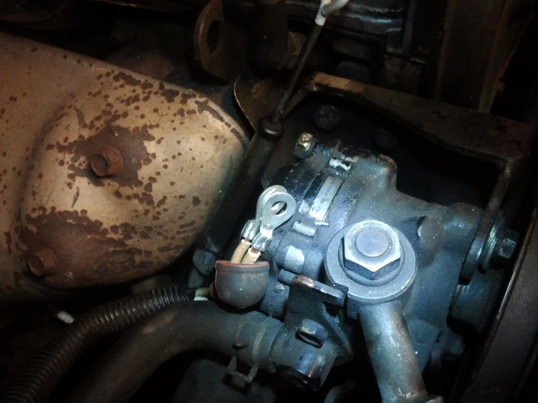
Once again, I found myself outside, at night, in Massachusetts, in the middle of winter, trying to solder.

I had to replace the B+ terminals that got ripped off, so I crimped then soldered some 1/4″-stud ring terminals on.
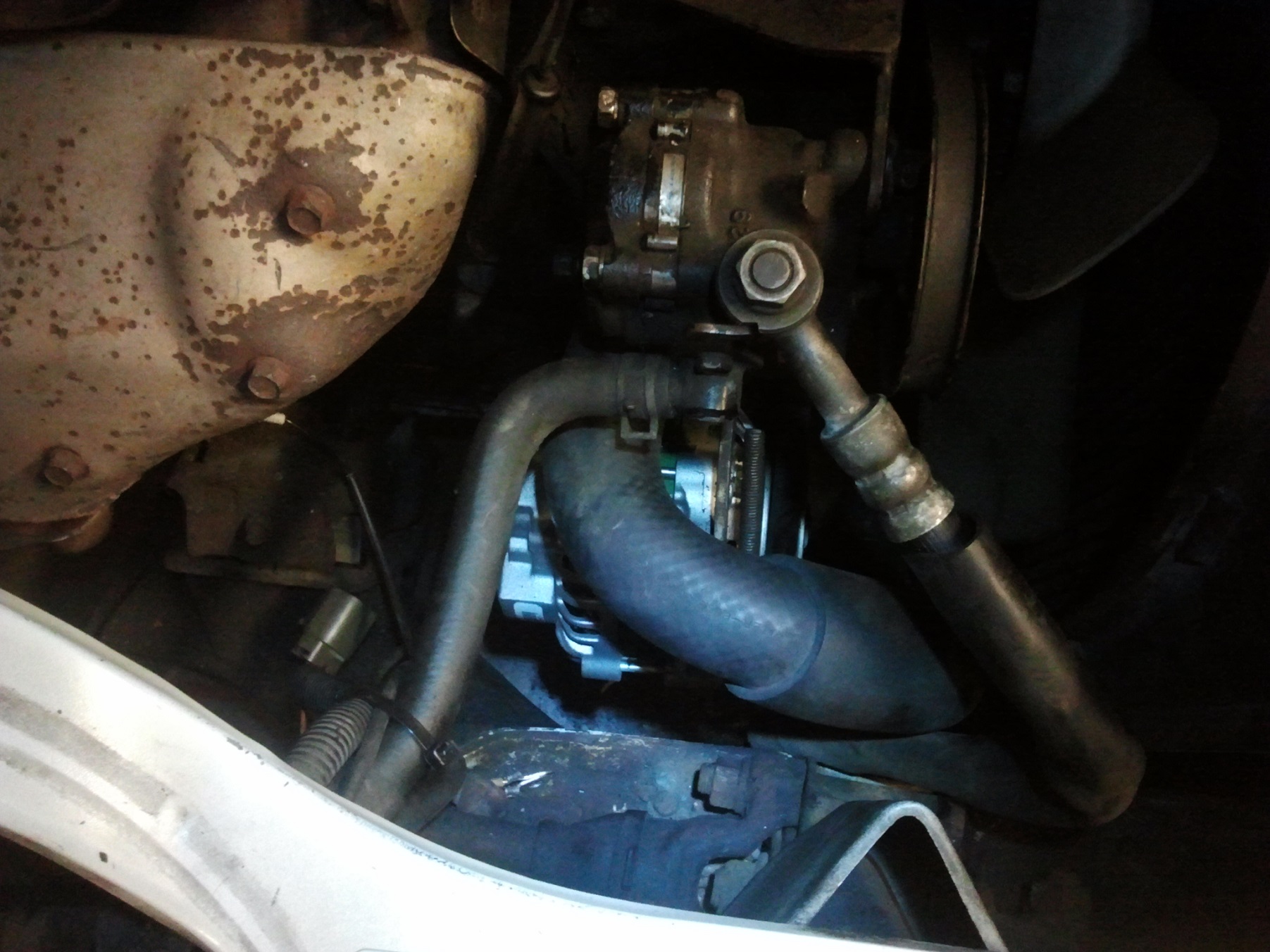
Here it is. At around midnight Friday, everything was back up and running. To reinstall the alternator, I carefully dropped it through the same hole the old one was fished out from, then some more deep-arming with a ratchet on the front side and everything was tight again.

There was only one problem. Either the new pulley is a tad smaller, or the alternator belt that was installed was of the wrong length, because I bottomed the tensioner out and still had enough slack to cause squealing problems at low engine speeds. This translated into neutral-coasting towards red lights while keeping the engine RPMs above 2000, where it could finally catch on. Consider it practice for a manual transmission, but this was how the entire Motorama trip went down (highway cruising wasn’t a problem, luckily).

Afterwards, I decided to try an experiment as long as new belts were within reasonable reach at local parts stores.

The Brief Tragedy of Slinkybelt

I’ve always wondered if adjustable-length V-belts were a legitimate replacement for a conventional endless V-belt. They come in a few flavors, such as PowerTwist or Acculink. The story is the same – interlocking drink can tab shaped beltlets that twist-lock into place and allow you to formulate a custom length belt, as well as install them like you would chain drives -no disassembling machinery. That last part I really liked the sound of.

The alternator belt is the last thing to come off before I start removing timing belt covers – it’s the last accessory belt in the disassembly path. I didn’t want to spent 6 hours doing all that again, so I took an interest in the adjustable length belts for this reason. I ended up discovering that I could violate general topology by threading the belts slowly over the 7 blades of the cooling fan, but this did not end my curiosity.

I bought a few feet of the Powertwist type off eBay last week. When I got it, I took the cheap shot route and cut the old belt off. Here’s a picture of Slinkybelt installed:
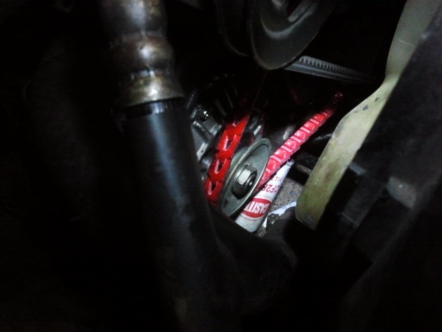
My initial assessment was that it seemed to work, but definitely “grew” more than a standard belt. This seemed to be indicated in the instruction sheet, so I was just happily adjusting the tension out to an absurd amount to compensate. It was also making rather unhappy slappy sounds, where it was advertised to be quieter….

Unfortunately, it blew up on the next drive. I noticed the unhappy sound growing louder, then suddenly it all went quiet and all the dashboard warning lights lit up. Awesome!

And that was all Slinkybelt wrote. The rest of it fell off on a side street somewhere around here.

A few robot builders on Facebook who had used this type of belting in large robot weapons noticed that I had installed the belt backwards. Wait, belts have a direction?! These do, apparently – whether the twist tabs travel  “leading” or “trailing” matters in how the pulley transmits forces to the beltlet bodies. Trailing is the correct direction; I had them leading. It seemed more intuitive, but it was wrong. There were arrows printed on every tenth link that I didn’t notice. On closer inspection, yes, there were, but they were heavily smudged or almost illegible.

Using my remaining stock, I fashioned a new one out of obstinacy and wanting to see if the claims made by its sellers were legitimate; user error doesn’t discount a product’s efficacy, in my opinion. After driving around a few days with the belt correctly installed, I’ve come to the following conclusions:

  • The urethane material they’re made from seems to have less traction against the drive pulleys than rubber. This results in slippage even if the belt tension is tight – it seems to count on a large wrap angle, such as those present in two-pulley industrial fan drives or something, where my alternator has maybe 110 degrees of wrap at most. I noticed substantial slippage at low engine speeds when the alternator’s field has to be more strongly energized.
  • The slippage failure mode makes very little noise, unlike the screeching of a rubber belt, so it was hard to just discern by sound. I was actually watching how bright or dim the dashboard lights became as a function of engine speed.
  • I did have to adjust the tension multiple times as the beltlets “bit” into eachother at first. This is probably more trouble than anyone would actually go to in practice.

Overall, I see the appeal for near constant speed and load industrial drives (like fans and pumps) which they are sold for. For automotive applications, I’m not sure if they’re worthwhile for the above reasons – wildly varying speeds and loads, plus a different general belt path topology that tends to give less wrap per pulley, meaning that the individual beltlets have even less surface area to grip with. The alternator has to deal with speeds between 1000 and 10,000 RPM (if I really hammer it from a light or tollbooth), and wattage loads of between maybe <100 to nearly 1000 watts if all the accessories are going full power.

Yesterday, I decided to end the experiment and spend half an hour violating said topology to install a standard drive belt. Slinkybelt will live under one of the seats to be used for emergencies, or maybe in a future robot.

That’s all for now! Next up, time to return to working on the tiny version of Mikuvan. If I’m not working on one van, clearly because I’m working on another…

Random Shenanigans to Break In 2014! Beyond Unboxing with Ikea Drills, LandBearShark’s Battery Surgery, More Van Nonsense

Happy new year and welcome to Big Chuck’s Automotive Blog! The mission of BCAB is to share and discuss all of our misadventures in being shadetree mechanics. Not only will I post all the questionably sound work on my own wreck, but every week, there will be one story submitted by you, the readers, about any aspect of your life pertaining to your own automotive project or rolling piles of garbage, whichever you would prefer.

I kid.

The way my site visits and interesting search hit terms have been slippin’ lately, though, you’d figure I’d have gone full-time car blog. Luckily, that’s only partially true. It used to be that I got plenty of weird and interesting search hits, site referrals, and the like. I feel like I’m losing my touch there – these days it’s all full of “electric bike” or “electric go-kart” or “How to avoid electric shock installing I’m a hybrid battery” (sic) and stuff. Booooooooooooring. Perhaps I should be glad that I’ve been genericized to that point, such that my content has become more generally relevant. But I do miss the days of the Arduino powered butt massager.

This IAP, I’m watching over MASLAB which is using the IDC classroom and my shop space, while also ordering things and preparing for the next round of 2.00gokart in the spring. MASLAB is historically a ‘shopless’ activity… which means that students break into or ninja the use of whatever shops they can get into in order to finish their robots. This year, they faced difficulty getting their usual space in the EECS department, and several of their core team and students being my former students, I got pummeled with appeals for space. Now, it creates way more work for me (what amounts to an actual full term class’s worth of preparation and shop orientation sessions), but what better way to spoil even more undergraduates? Furthermore, I think it’s better for them that they have official access to much more resources that can be properly used (i.e. under my titanium fist rule) than students trying to steal and beg resources from any space they have access, or “get” access to; which in my mind is patently unfair to those who are also just starting out and don’t Know Somebody – MASLAB is often one of the first “Build a robot” things a lot of freshmen do.

Anyways, I went to Ikea:

I defy anyone to challenge me for the title of “Best Ikea Space-Filling Ratio”. Flat-pack furniture works best with a vehicle which can be 90% modeled in no more than 3 solid modeling features.

Now, none of this is actually mine, since my own life is containerized into a number of typical milk crates, and I wouldn’t touch anything Ikea produces with the most bargain of Harbor Freight allen wrenches. But while on the tour in the most perfectly structured consumerism experience, I naturally gravitated to their tool section. The selection was naturally all custom-commissioned products geared towards assembling only their shit – again, part of the most perfectly structured consumerism experience this side of Buy & Large.

1. Beyond Unboxing: Ikeaworks (FIXA 7.2v drill)

(To quickly skip to the other sections, here’s…

2. Landbearshark’s new battery

3. The Weekly Van Shenanigan: Bodywork, oil pan gasket, and fixing that subyiffer

I spent a little while looking at the FIXA (I keep wanting to say Fixya) power tool series – they have things as interesting as a 14.4v hammer drill and a standard two-speed drill. Ikea being an entity that nominally prides itself on inexpensive low-key quality (as opposed to, say, Harbor Freight, which prides itself on Fuck You), I did expect that these tools would have worked just fine in their intended household lives. It’s like a domesticated goose – all you really need is a guarantee that it will poop everywhere, perhaps not with the flamboyance of a wild Canada goose.

I found their 7.2v drill/driver interesting. This is because it evoked the shape and function of the classic Handiworks mini-drill found at Walmarts back in the Early Noughties. This little thing fueled the rise of the 12lb weight class. For a while, Harbor Freight carried a 7.2v variant which made it into the 2nd and 3rd iterations of my own Test Bot. That was about 2005-2006. Those drills disappeared with an increasing RMB to USD trading ratio, as did most of the low-v0ltage (9.6v, 14.4v) drill/drivers from Harbor Freight.

An overwhelming sense of curiosity and nostalgia drove me to pick up one of these units. I’ll say right away that for $24.99, it may not be worth it in general, even if it were identical to the old Handiworks. However, the package ended up being more compact and a higher ratio – it definitely could be robot-applicable for somebody. So thus begins the Beyond Unboxing of the FIXA 7.2v drill/driver.

The casing is shed with a few Phillips-head screws from one side. No hidden screws here. The first thing I found is that it really IS lithium ion! There are two cells, 1500mAh each, size 18650, of lithium cobalt or lithium manganese chemistry (not LiFePO4). These 1500mAh cells contrast with the modern generation of laptop and other device cells which are typically 2400mAh, likely because they are “power” cells made for industrial use – wider temperature ranges and higher allowed burst currents – than “energy” cells which simply try to provide the longest runtime.

It has a cute little BMS board attached to it that handles both charging and discharge protection. The large FET at the top is connected to a current sense circuit that actually causes the drill to shut off if it’s near stall or suddenly locks up. This manifests itself as suddenly losing power, but it resets once the trigger is let go of. A nice protection to have if you sell your tools to total rubes for sure.

This current sense circuit depends on a sense resistor, which, like the Jasontrollers, can be easily chopped to a lower resistance if somehow you are compelled to do so, God help ye.

Four more screws and the gearbox comes apart. The gearbox is unlike the standard 36:1 or 24:1 drill gearbox. Rather, the gears are somewhat smaller in pitch, 0.6 module by my closest guess (about halfway between 32 and 48 pitch, which is what they look like). What was surprising is that the first stage of the geartrain is all metal. Usually, the first corner to be cut on these is to replace the first stage with nylon gears, ostensibly for noise reduction but we all know really why.

The gearbox is 3 stages of 16:14:45, resulting in a total ratio per stage of 3.8125 and a final ratio of 55.41:1. The final stage has 5mm thick gears, compared to the 4mm thick in the rest of the thing, to handle high torque demands.

The ratio is a little high for my tastes for a robot drivetrain, but for those not aiming to hit 15-20mph, perhaps just a slightly larger wheel will suffice. Remember that I’m clouded by a decade of smashing robots into each other; very few parts which are generally useful make it into the top echelons of the battle-tested.

I wasn’t quite curious enough to take off the chuck, since the left-handed locking screw was better installed than most Harbor Freight drills and I wasn’t in the shop at the time. I suspect that the traditional drill gearbox bellhousing, albeit in a smaller size, is on this one. The drill shaft is also most likely a 3/8″-24 thread like normal, but I won’t speculate more unless I have it taken apart. It has a nominal rating of 400RPM – which, through the gearbox, yields a motor speed of about 22,000 RPM, in line with the typical small drill motor. The motor in question is a 7.2v Mabuchi RS380 knockoff, unlabeled.

2. landbearderp

Remember the Landbearshark video? Well, after that and the additional snowstorm a week ago…

Whoops. I guess I went a little too hard. I noticed something was wrong after the batteries never recovered above 16 volts even after a day of sitting. Both battery packs had cell groups which were either at 0 volts completely, or at severely damaged levels like the 1.38v group above. This was the batteries which caught fire once and also survived months of tumbling in the original Landbearshark, finally having been done in because the rest of the thing worked too well.

Damn. Well, with the potential for more weather in the next few months since this winter has really been making it rain snow, I had to replace the damaged batteries before LBS could work again.

I went digging in my lithium nuclear arsenal, which I obtained after the MBARC class ended and I confiscated all the lipos (with exception of those taken by R/C airplane experienced students). Most of the packs were in the 5S and 6S range, which was good for LBS, but they did not have built-in battery management boards and I didn’t want to add a big balance harness to LBS. However, there were also these:

One of the teams went commercial/industrial and picked up these from Batteryface. These are sold with a “PCM” module built-in, so they don’t need to be externally balance changed. I’ve used these boards a handful of times before in not-my-own applications, and they do work just fine, but I find them a little too wimpy on the discharge: for most high burst current or other high power apps, I prefer running straight battery, because the management board usually introduces more resistance or has built-in current limits.

But LBS is not particularly high power. I could also fit four of them in the space left by the 6S6P A123 pack, netting me much higher energy density: 22.2v 40Ah instead of 19.2v and 26.4Ah. I’d trade the unneeded brute force for ease of use and built-in protection.

Sounds like what these were made for! So in they go.

To get four packs in the space of two, I had to put Y-harnesses on my Y-harnesses. I chopped the discharge leads off my old battery, which had a type of 6mm bullet connector I no longer had on hand, and spliced them to two Deans plugs each. The students added quick disconnect terminals to their batteries, which I cut off and replaced with Deans.

Installing the batteries was a fun game of OH GOD DON’T TOUCH THE FRAME RAIL WITH THE EXPOSED PARALLELED CONTACTS.

The batteries are mounted to the electronics box with strips of Velcro. Their height is just under that of the box itself, so they shouldn’t be going anywhere.

Suddenly, the wiring looked less nest-like than before. Not because I made it better, but now all the excess runs were the correct length to tuck next to each other! Science.

LBS has yet to make it back outside since the weather has been… “nice”? Test riding around the building showed me that it was very much more responsive. Not only because the voltage has jumped a few from the A123s, but that the batteries must have been damaged for a while and have been sagging more for the same current draw. Hopefully the next bout of winter commuting will put these to the test.

Rewinding before the new year once again, I’ve officially commenced…

Operation: RUSTY MEMORY

It could refer to several things. First, the old magnetic disc drives that used straight iron oxide (rust) to store information; the earliest kinds that went into the “refrigerator” hard drives. Next, the fact that you can’t quite remember something.  Finally, all of the really shitty bodywork I’m about to do to prevent more problems down the line.

I’ve been leery of doing bodywork for a while, despite a slow buildup of arms in the interest of doing so. The past has shown me that I have no patience for making smooth and clean lines or blending paint. However, the recent pressure of winter and its associated wet salt slush has caused me to examine some of the spots in more detail. I’ve determined that there’s some areas where I’m getting close to now-or-never, because the underside and “hidden” rust. Remember these boarding step holes? They’ve gotten bigger:


Soon, they will soon break the outside body lines… and hell if you’re getting me to rebuild external lines. Other trouble spots include the majority of the left underside for some reason – the right side is pretty clean, but the left is all sorts of beat up.

Before tacking the more complex curvature of the step, I decided to practice more on a less visible spot – the left rear corner. Here’s what it looked like in May:

A complex confluence of edges in the corner with quite a few holes and thin areas to patch up. The plan I formulated was to cut away as much of the bad areas near the holes as I could get, then grind or wire brush off the rest. About two weeks before starting on this, I thoroughly coated the interior of the bodywork in the area with that “rust converter” compound and let do its job for a while. Hopefully this will help prevent the interior sheet metal from being a problem in the near future.

Let’s get started. I once again dibbed the corner of the garage for a weekend, though I didn’t need the lift. What I did need was a spot that wasn’t -30 degrees out, so things could actually cure.

When I was using the lift before, I had noticed that the arms block the area I need to work on, regardless of orientation. So I had to use a whole trade of jackstands (the proper collective noun for jacks is a trade) in that area. Since I’ll be violently thrashing on this area for a while, I used not only a stand on the frame, but on the corner of the rear suspension also, kept the floorjack a little pressurized under the differential, and chocked both right wheels in both directions. A little paranoid? Perhaps, but I also prefer to have thickness.

This is what that region has devolved into since that time. The holes have grown a bit, and much of the weaker rust has fallen off. The treatment compound is seen in green.

The excise begins by gently hammering at the panels to loosen up more internal rust. This is item #2 on the list of 3 things Mikuvan does very well: dropping little flakes of rust everywhere. The other two, of course, are emitting black mucuses of various viscosities, and raining bearings.

Maybe I should have done this before spraying the converting compound…

Next up is imprecise angle grinder cutoff wheel excise. The biggest trouble spots went first.

About 1/3rd way through the process. When the angle grinder became too unwieldy to maneuver, I switched to a Dremel with a small cutoff wheel. My goal was to eliminate as much of the obviously rusted metal while retaining features that will help rebuild the area. I cut off a piece of the wheelwell (the right angle upside-down-L cut is center in the picture) to gain more maneuvering space for cleaning the area behind it. After the cutting, liberal application of wire wheels knocked out the rest of the surface rust in the surrounding area.

What I do not have is a picture of the completed surgery, since much of this process was mentally streamed. More of the steel on the inner wall to the left was removed, as was the area with the perforations in the upper left, extending about 4″ towards the front (where the wirebrushed paint starts).

I retained my tactic of using 3 layers of fiberglass cloth (I’m not sure of the weight, but it is pretty heavy) that were nipped from Solar Car.

I decided to split this work into two sessions to make sure I didn’t have to hold onto too many things at once. I patched the outside first and let the glass cure overnight.

The next day, I worked on the inside. To cut the cloth to shape, I just mashed the fabric against the repair area and used a marker to get the rough outline, then cleaned and simplified the marker scratches to a cut pattern. The pattern was used as a template to make two other pieces, each very slightly smaller. The marker dissolving into the fiberglass resin is the cause of the blue outline.

This area looks pretty gnarly because of the untrimmed glass and the fact that I didn’t try to rebuild the down-facing curvature of the original body section.

The day after was cleanup, filling, sanding, and painting. The tattered glass edges were trimmed flat with a Dremel and cutoff wheel first, then the whole area manually sanded with a sanding sponge and then some fine regular sandpaper. I used a small amount of Bondo to smooth the transition between the glass layers and the remaining bodywork, but as the masked area shows, did not attempt to resmooth the surface from where I wire brushed off the paint.

Paint was the same procedure of primer, color, and clear I used on the rear hatch. This took several hours by itself, then I let everything dry overnight once again.

Once the outside was dry enough to put some masking tape on, I sprayed a few coats of underbody coating compound on the inside repair to seal it as well.

Here’s what it looked like as of a day or two ago – it’s gotten a little dirty since:

I make no claims to ever passing auto body school.

Based on my research, a real auto body guy would have removed far, far more metal than I did, and also have remade at least some of that inside corner box section in steel, if not straight up remake the entire sheet metal of the wheelwell area. When I can afford this service, I suppose I’ll have that done…

I’ve learned since that they make this stuff called “spot putty” which helps fill in the very small resin bubbles that are visible; plus that I’m not spamming enough resin onto the top ply to start with, a phenomenon also visible in the rear hatch work. These lessons will hopefully be put to use in repairing the boarding step hole soon, since that is a more visible location (with the door open, anyway).

Subyiffer

A quick break from inhaling styrene and toluene led me to try and figure out exactly what the deal was with the “subwoofer-like device” that I touched upon previously. I thought it was barely working, but it turned out to be sympathetic vibration transmitted through the front sheet metal and dashboard components. It was in fact totally out.

I’m sure a normal person would have replaced this with a set of 12″ subs in the back, but I dunno, it’s already there and most likely working anyway. What if it was as simple as some dumb fucker not connecting one of the wires? Wouldn’t I feel foolish for not trying to make use of it at all!?

Besides, the 12″ subs come after the electric drive conversion, as do the tacky underglows and stancing.

It was 20 degrees out, in the middle of winter, in Massachusetts. And here I am, outside, with nothing but flashlights, using an oscillosope and soldering iron to probe the paths that the signals took in an attempt to debug the amplifier board. Consider the frightening possibilities if I had put this much effort into actually studying something.

I ran into a slight metaproblem – it was so cold that my small cheap soldering iron, which travels in the robot service toolbox normally for use in the field at events, froze its power cord off. Literally. It probably deplasticized in the cold and in the process of me unfurling the cord, it broke off.

I borrowed a Weller station from MITERS in the mean time, which seems to use a plasticizer that didn’t also grow up in the South like me.

So if you’re ever stuck debugging the subwoofer amplifier circuit of a generation 3 Mitsubishi Delica, here’s what it is. The whole thing is OEM’d by Matsushita (a.k.a Panasonic). There’s 7 wires leading to the board – three of them are the ground, 12v, and “power on” lines shown, the others are two channels of signals and their return lines.

What the frontend of this amplifier does is add the two stereo channels together, then severely low-pass filters it before sending it to the amplifier power IC. This is all done actively, with op-amps. In fact, the circuit is eerily reminiscent of this generic mono amplifier circuit.

The ENABLE line controls the coil of a little relay that is in between 12 volts and the amplifier chip. Guess which wire was open circuit?

Naw, couldn’t be that someone forgot to wire it up.

(Alternative explanation: The new head unit that came Free With Purchase did not have an external amplifier enable output, so this was left unwired, but that doesn’t explain why someone took the speaker totally out…)

I took the cheap and dumb way out: Jumping the enable pin directly to 12 volts. When I turned the ignition key, I heard the faintest click of a relay and a little pop from the speaker.

Scoping the speaker’s terminals shows this nice waveform coming out. The cutoff frequency does appear to be around 150Hz.

I packaged everything back up after this fairly simple hack, and immediately ran back inside to defrost. Let’s be honest here – this little thing didn’t add that much to the experience; finally some noticeable low end now, but it seems that it saturates (clips) relatively easily. Not that I blame it at all. It was another box ticked off on the checklist of completion.

Oil pan rebuild

Item #4 on the list of things Mikuvan is good at: leaving small droplets of oil wherever it goes.

It’s done that ever since the first start. I’ve always attributed it to a crank seal problem, but recently I started suspecting otherwise, because the symptoms didn’t really line up with just a crank seal issue. If I had a leaky rear crank seal like I suspected, then the oil drops would be coming from very specific, concentrated locations. Same goes for the front seals. I’d at least see a consistent, concentrated ‘shot pattern’ from the two locations in my parking spot… which I assure you is terrifyingly disgusting.

Instead, it just seems like it’s been shitting everywhere. Since I’ve been getting under it more recently, I’ve also been keeping track of the cleanliness of the underside: Every time I look under it after cleaning up all the oil and grime, there’s more of it everywhere. There was no one consistent spot at all – the whole underside near the engine would be wet all the time and spots would appear almost at random. It was less oil leak and more Self-Applying Undercoat.

As the weather got colder, it just started getting ridiculous, and once again I was faced with a now-or-never scenario. I was beginning to suspect the oil pan gasket a few weeks ago when I first began noticing that it was always wet on the outside. Hey, shouldn’t a gasket keep the leaky stuff on the inside?

During the suspension work on the lift, I gave that area a very fine look-over.

This is the forward left side of the oil pan. First, that gasket is pushed out completely and ripped. Second, it’s disgusting.

I figured, once again, that even if it was not the main problem, it could be a contributor or aggravating factor, and that I should at least inspect it. I braced myself for yet another Yak Shaving Session where I end up having to remanufacture the entire assembly. How bad could it be!?

(Always Famous Last Van Words)

I looked at the service manual for a bit and then began disassembling the oil pan screws.

First to come off is the oil level sensor. I have no idea how this is supposed to actually work – and it just barely does. Usually, if I park on a non-flat area, it’ll throw an oil level light; and not knowing how leaky the thing actually is, I check every time, only to find the majority of the time it’s totally fine.

I have no pictures of the pan removal process, since my hands were well-covered in oil, and the whole thing just sort of fell off after I undid the last screws and put a little pressure on it with a scraper. Well, that’s certainly a bad sign. From my Youtube instructional video surfing, you’re almost supposed to use said scraper to cut the whole thing off.

Oil pan removed! This is the first time I’ve ever physically seen the inside of an engine, from the bottom end. Who the fuck thought this was a better idea than a brushless motor?

The fact that oil is everywhere on the alleged gasket sealing surfaces is, again, not a good sign.

So here’s the deal with the gasket. First, on top, there’s a layer of silicone. Not, say, specially formulated gasketing compound, but I swear it was just clear RTV used for bathroom tiles.

Next, there’s a paper/felt sort of gasket, the type that you would buy specifically to fit a model of engine.

And finally, there was another layer of silicone. 

Silicone-on-paper-on-silicone didn’t exactly strike me as a professional repair. I suspect, again, that this was like 5 different dudes’ repair hacks and I am the 6th.

Unlike bodywork, I considered this a blasphemy against the  mechanical gods. I rage-cleaned and stripped the entire pan, paying special attention to the gasket seal surface. I also cleaned up the bottom of the pan some. Luckily, there were no metal particles to be found, but there was a sizeable amount of brown and black sludge; likely from before I was also meticulously keeping track of oil condition.

Here’s a shot down the line of crankpins and big ends. Once again… who thought this was a better idea than twirling a magnet (or a blob of copper and steel) on a stick?

Here’s a picture of a 3-floor building sized engine’s crankcase while we’re at it. It’s only a little bigger.

I didn’t get any pictures of the re-gasketing process, but it entailed borrowing a small amount of this RTV material designed for gaskets and laying it out in a roughly 1/8″ wide bead in the pan’s top groove, around the outside perimeter, and in a circle around the bolt holes. I then let this cure overnight under the influence of a halogen lamp, and retorqued the screws according to specification the next day.

After a week and a half of this, I’ve only seen 3 new oil drops after having placed a white spill mat on the concrete parking spot. They were concentrated around this spot:

I didn’t notice this little vent in the bottom of the transmission bell housing until I was under there looking at it. Under the cover is the torque converter and its crankshaft adapter plate. If I had a crank seal leak, I would have seen the majority of the oil drops originate near here.  It might still be leaky; I have not confirmed its health in either sense. For now, however, the oil-shitting problem seems to have been resolved in the majority.

This concludes the latest Big Chuck’s Automotive Blog entry. Make sure to check back next week as I make even more mechanics and auto body technicians cry!