No, this has absolutely nothing to do with Ke(§, Š, Σ, ∫…)ha, but it’s been more than a month since the last Deathblades update. Charles, where are my Deathblades?! Aren’t they supposed to be done by, like, last year?
I went through a flurry of work before the De Florez award judging in order to have one skate power unit on display. As we all know, that didn’t go too well, and I spent a short period of time afterward wallowing in self-pity, loathing all that Mechanical Engineering stood for, and recklessly experimenting with Course VI (you know, a harder substance). About the same time was when virtually all my carbide indexable lathe cutters were chipped or broken and the shop had exhausted its consumables, such as bandsaw blades and most importantly, sanding belts. So overall, there was very little incentive or motivation to work on the ‘blades during most of May, especially with LOLrioKart finally working well enough to hoon, and the Media Lab’s spring Sponsor Week in full swing.
Here’s some of the progress from the week of May 4th.
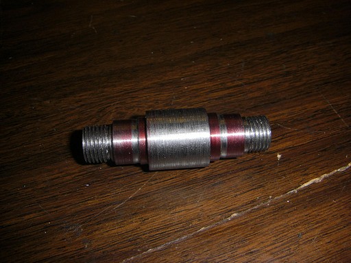
This is a Deathblade axle. You may revel in the disgusting surface finish.
It’s dimensionally acceptable, but I had to machine most of the diameters with chipped carbide indexable bits. I leave my set out for the populace of MITERS to use, but unfortunately not everyone knows the handling differences between HSS and carbide. About this time, I placed an order for new tips, but because of the whole transcontinental shipping issue, they would not arrive until the middle of May – so I pressed onwards.
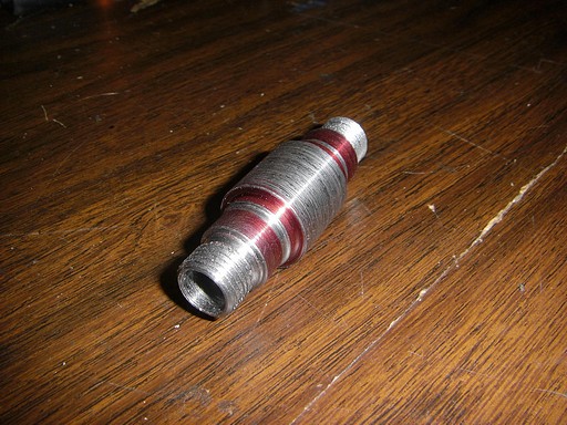
The terrific finish is more apparent from this angle.
Those end threads were single-point cut with a threading tool. I’ve gotten decently fast at threading from making the motor cans, but I still need some technique improvement (and a non-dull threading bit, but that was coming in the order). I got into the habit of reversing the whole machine (disengaging the threading nut) such that by the time I’m back at the start of the thread and had finished making dimensional adjustments (returning the cross feed to my set zero and advancing the compount), it was nearly time to re-engage it and throw the machine back in forward.
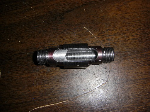
A plan view of the Negative Volume of Wire Accessing. I’m using a slightly different technique than the scooter motors in that all the wires will come out the center of the shaft – not through a keyway or flat. This time, the axially drilled hole meets a radially-milled slot within the confines of the motor. It leaves plenty of room for termination and is a fast setup and operation.
The center hole is 3/8″ in diameter, and the slot width is also 3/8″.
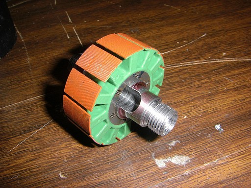
Stator test fit!
One side effect of the material removed by the drill and slot is that the axle is somewhat springy at the center. When I press a stator on, that portion of the axle deforms slightly and preloads the fit.
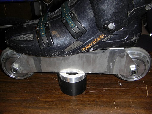
Motors quasi-assembled and installed for a test fit. I ended up pressing the stator back off for the display item because that would have made assembly and disassembly more difficult with the magnets already installed.
The future electrical harness would exit the motor and immediately curve back towards the center cavity. For experimental purposes, I’ll probably just drill holes, run the wiring inside, and leave things permanently joined – but I could see a frame-mounted connector for any Legit™ versions.


