In another episode of “Charles digs out old and semi-abandoned projects to work on them because he currently can’t afford to work on new ones“, I spent a day fitting the Landbearshark with front and rear load cells in the interest of converting it to fully hands-free operation. I’ve gotten it to the point where I have created a noisy and metrologically unsound bathroom scale, finding out just how fat I am.
A few months ago, I redesigned the pivot mount for the skateboard to include provisions for mounting a cantilever load cell on either end. I actually received the load cells a few days after finishing the new hinge and trying the hands-free steering, but just stuffed them away for the time being to focus on other things, such as Tinytroller and…. what the hell else did I do this fall? I also didn’t want to take LBS apart again and have it in a non-working state as the winter approached, since I figured any snow day romping was better than none, hands-free or otherwise.
The problem is, it seems that by virtue of being fully functional, LBS has delayed or neutralized the winter snowfall. For the past few weeks, it’s been either
- Mid 40s and 50s, like spring or late fall, and raining really heavily, or
- Single digits temperatures, clear and windy. Really, really windy.
If it’s going to be this cold and depressing, I’m going to move back South, where they have nicer 3d printers.
Either way, I’m making it official that LBS is not in a working state right now due to the load cell experimentations. There. It should start snowing tomorrow, right?

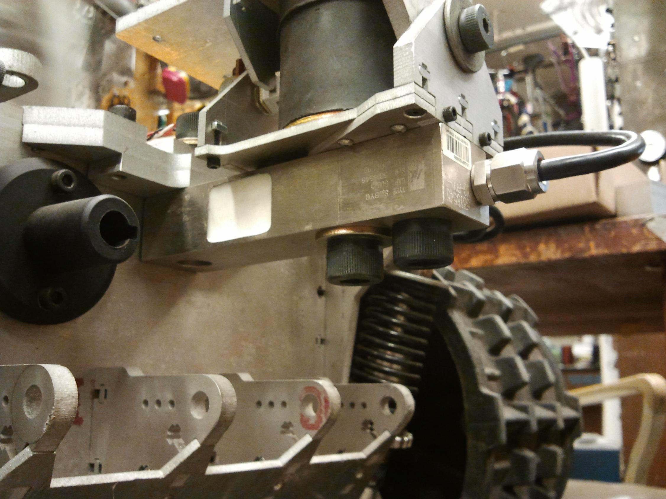
The load cells are 500lb capacity bricks of steel that I selected through extensive eBay research (read: “Price + Shipping: Lowest First”) made by Keli Electric. I decided to royally overspec them because the flexure sections of these beams were to be the only mechanical link between the board and the rest of the frame, with no hard stop to take up overloads past the maximum load deformation. In a better constrained application, they’d be really overkill for sure.
They came with little certification sheets that seem to be standard to all load cells, including specifications such as sensitivity in millivolts of output per volt of excitation (at full scale measurement), input and output impedances, linearity tolerances, etc.
They also have quality control stamps on them, presumably meaning “Yeah, it’s shaped correctly and has the right number of wires coming out of it”. There’s still something about Chinese QC stickers that makes my inner Chinese migrant worker tingle a little.

Because my pretend-o-cells were made to the same dimensions as the real thing (or vice versa), they dropped in place quickly. The only difference is that they were 1″ thick instead of 1.25″, which warranted shaving 1/4″ off the bolt lengths on the lathe.

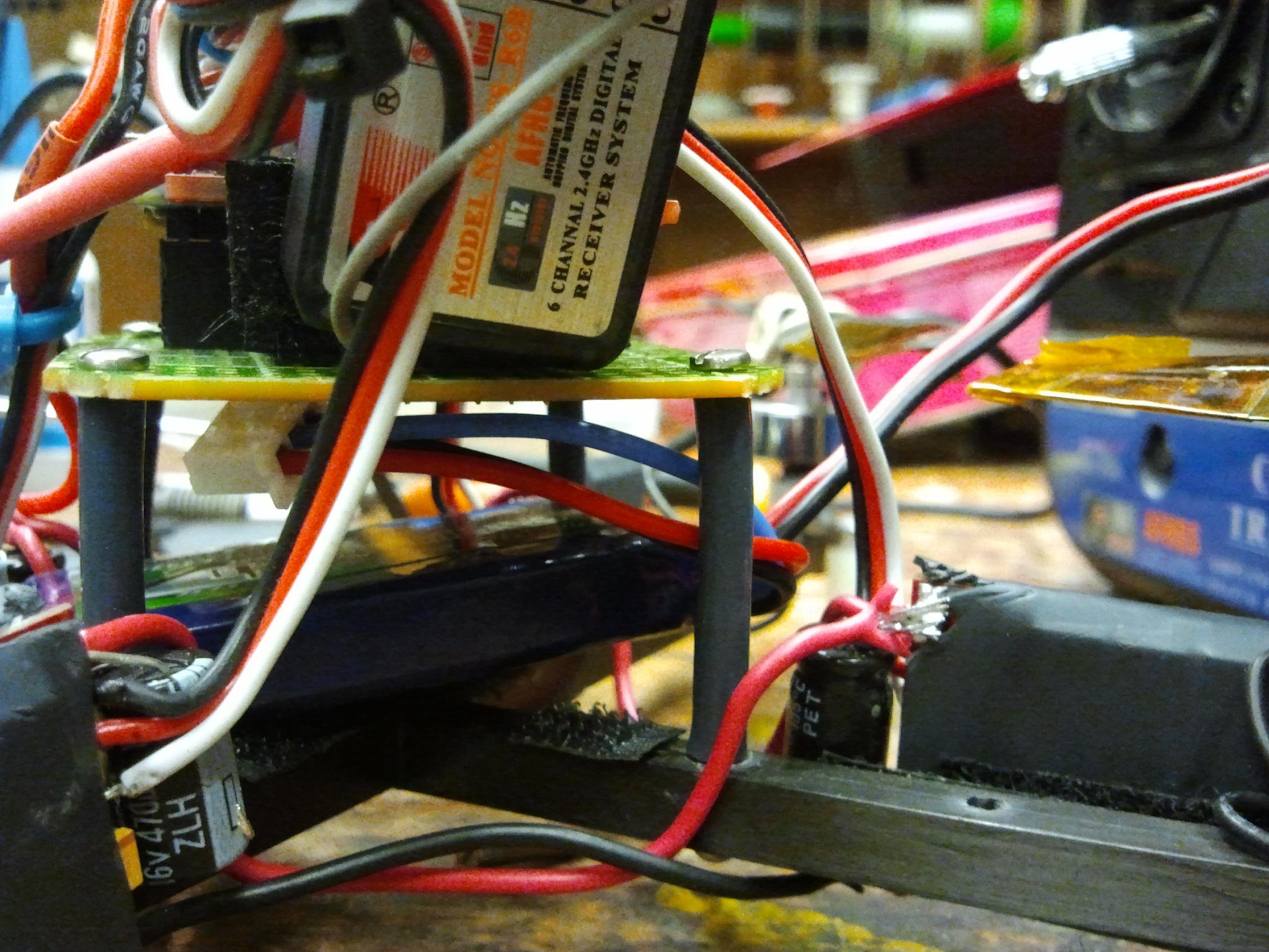
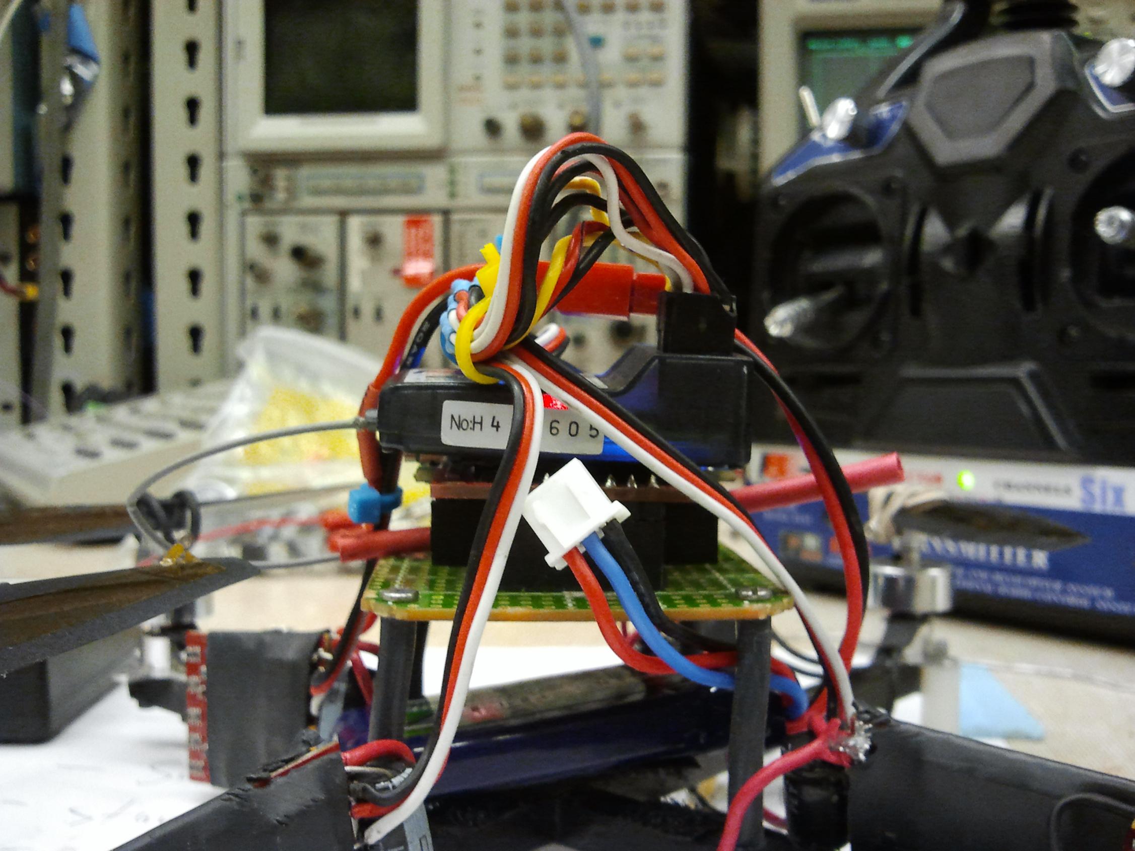
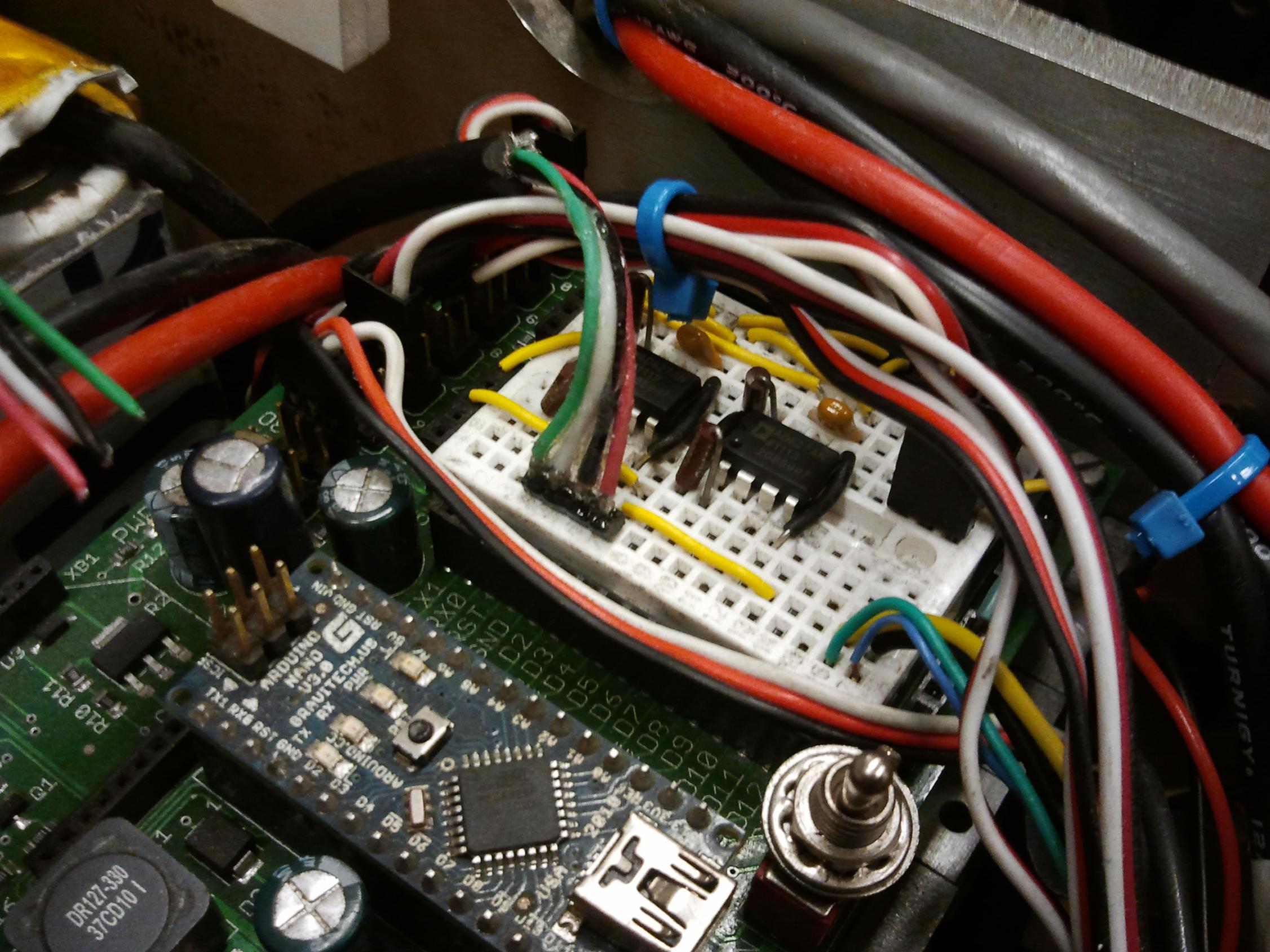
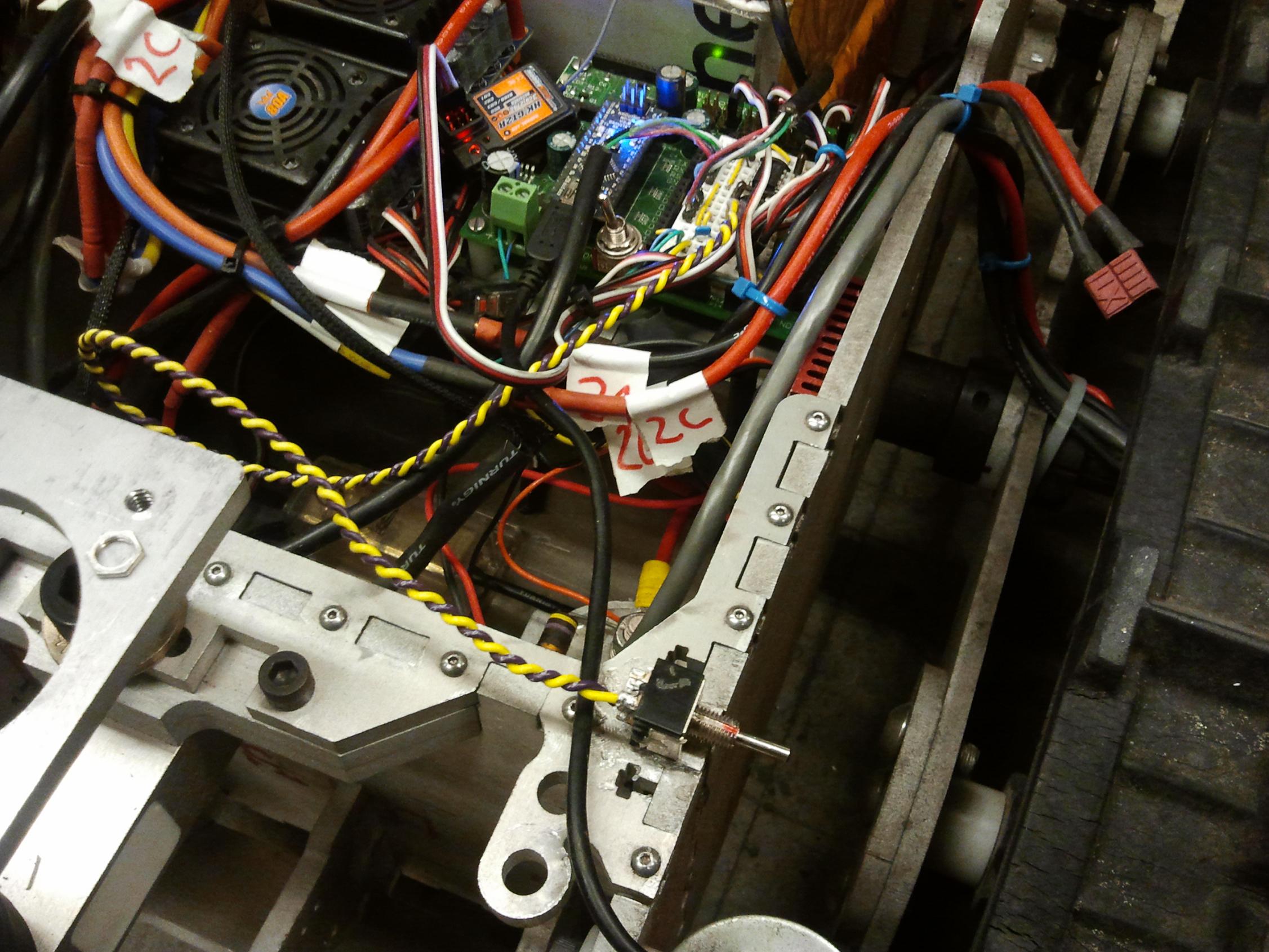
I whipped up a quick dual amplifier circuit using some AD627 instrumentation op amps from Anabork Devices. These things are expensive. Not the most expensive op-amp I’ve had the joy of playing with, but I had to buy them myself this time. I chose to do that instead of trying to put together multiple discrete op amps into a differential-input, instrumentation amplifier config because of the limited space on this breadboard and the fact that prepackaged amps allowed me to change the gain with only a single resistor. Breadboard on a vehicle. Bad idea? Yes. Convenient? Hell yes.
With 5 volts of excitation and 3 (+/- a bit) millivolts per volt, I was looking at only 15mV at 500 pounds full scale. I wanted to bring that to a full 5 volts of swing for mathematical convenience, necessitating a gain of 333 or so. Using the only 1% precision resistors I could locate at the time, which was 2 301 ohm resistors in series, I can get a gain of about 337. That’s like 333, right?

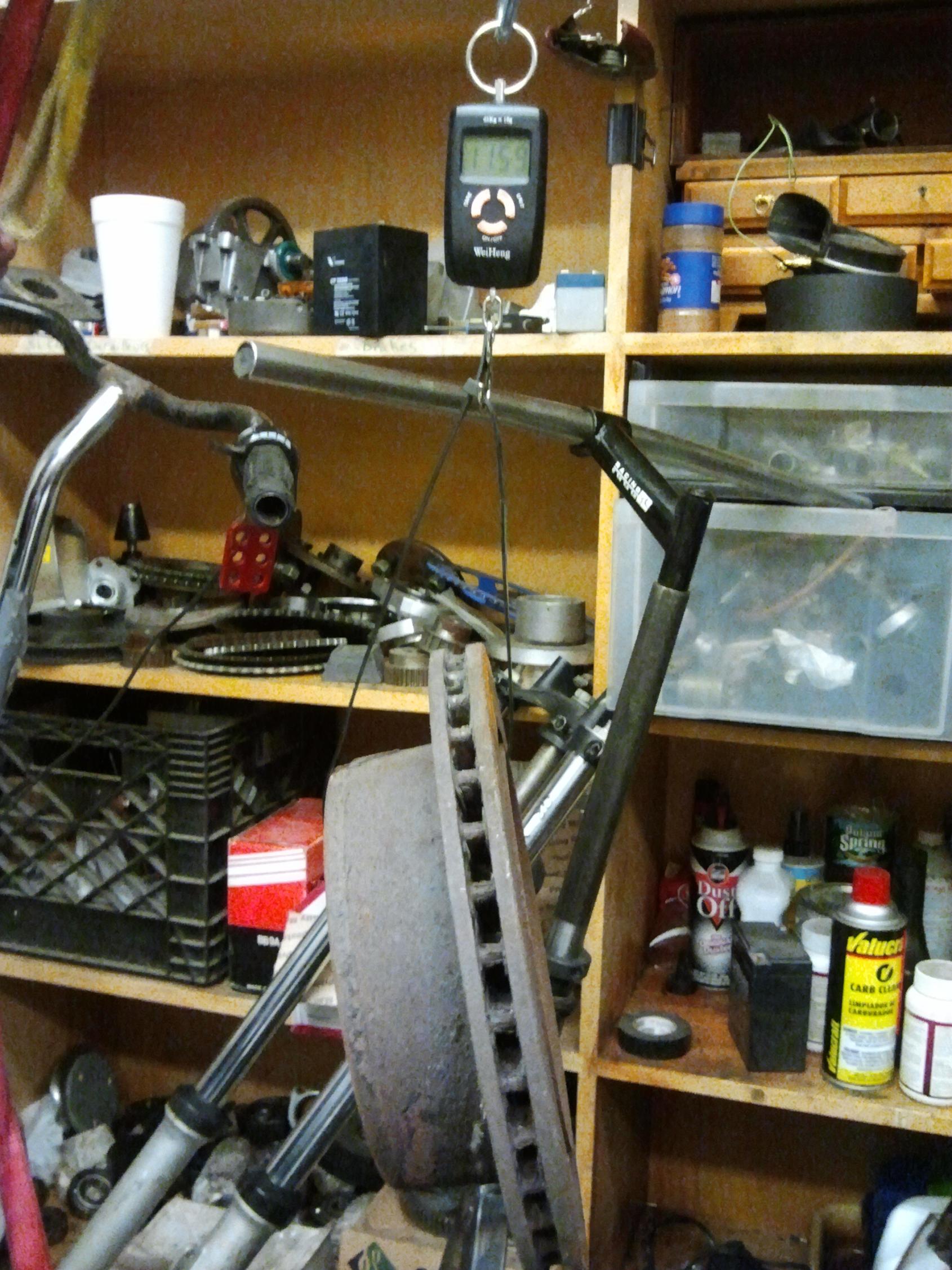
All the math in the world doesn’t prevent physical systems from behaving nonideally or me from being lazy and taking shortcuts. Therefore, I wanted each load cell calibrated with a known mass. I selected this 11.6 kilogram truck disc brake found in a corner of MITERS (placing pretty high in the “Weird shit found in MITERS” contest, actually) as the calibration mass. To find the actual mass of the thing, I used a cheap hanging digital scale.
Calibrating one shady Chinese scale with another shady Chinese scale. This is the pinnacle of Instrumentation and Measurement achievement.
The actual gains found were slightly higher at 334 and 352, +/- a MIT Mechanical Engineering degree or two. Each load cell also had a “zero reading” that was subtracted beforehand.
After calibration, I determined my internal ADC-LSB-to-kilograms-mass conversion was about 4.5. This is not going to be a very precise scale, but I’m not trying to measure weight down to the millinewton anyway. The shifting of weight is what will be controlling the vehicle in the end.

When I started writing the load cell reading-averaging code, I decided to include a “zero” function which pauses the entire vehicle operation, takes several measurements (namely 32, spaced 10 milliseconds apart) of the load cells, averages them, then saves the result to EEPROM to use as a new zero on the next power cycle. This was done because I did not, and could not assume, the final weight of the skateboard in order to hard code in a zero. The idea is that this would only be done once or twice after everything’s mounted, and not on every power cycle.
I had to figure out how to split a 16 bit integer (the output of the ADC from reading the load cell) into two bytes in order to stuff it into the atmega328’s EEPROM sector. I crosschecked my result with the Internets, and… hey, I diditrite.
Reading:
  //eeprom 10: low byte, front zero
  //eeprom 11: high byte, front zero
  //etc
  front_lc_zero = EEPROM.read(10);
  front_lc_zero += 255 * EEPROM.read(11);
  rear_lc_zero = EEPROM.read(12);
  rear_lc_zero += 255 * EEPROM.read(13);
(The 255 multiplication is equivalent to left shifting by 8 bits anyway – I was lazy).
front_lc_zero et. al. are unsigned integers. Essentially the “high byte” of a 16 bit long number is the low byte but multiplied by 255, or left-shifted by 8 bits. Hence, first populate the variable with the directly-read low byte, then add the future high byte, but shift it leftward past the existing 8 low bits.
And writing:
    fznew_lowbyte = ( front_zero_new & 0xff);
    fznew_highbyte = ( (front_zero_new >> 8) & 0xff);
    EEPROM.write(10,fznew_lowbyte);
    EEPROM.write(11,fznew_highbyte);

    rznew_lowbyte = ( rear_zero_new & 0xff);
    rznew_highbyte = ( (rear_zero_new >> 8) & 0xFF);
    EEPROM.write(12,rznew_lowbyte);
    EEPROM.write(13,rznew_highbyte);
where fznew and rznew were the zeroing averages, 16 bit numbers.
This took me much longer to figure out. The first operation (front_zero_new & 0xff) performs a bitwise AND between front_zero_new and the hex number 0xff, which when expanded to 16 bits is the binary sequence 0000000011111111 (or 0x00ff). It has the effect of cutting off the high byte of front_zero_new, leaving just one byte (the lower 8 bits). This byte is written to memory.
The second operation saves the high byte by just shifting right 8 bits (or dividing by 255, integer). The existing lower 8 bits are right shifted out of existence. The upper byte becomes the new lower byte, and this temporary representation is saved to memory. I didn’t have the second “& 0xff” at first, and it seemed to work just fine, but apparently it is good practice to apply the ‘bit mask’ anyway just to make sure nothing remains in the former high byte.
I used Arduino’s built-in EEPROM library to do this, so it probably did many horrible things to my carefully crafted inputs, but the results are legit. The happy zero point of my load cells, with the skateboard installed, seems to be about 623/1023 (Front) and 628/1023 (rear), in ADC least significant bits.
ui design
At this point, with the ability to read and save two load cell readings and roughly determine where my weight is concentrated, the problem has progressed to user interface design. I anticipate first trying a naive, absolute weight shift (difference between front and rear readings) kind of throttle control, but ultimately I want to create on that is adaptative to user weight and normalizes the throttle response with respect to it.
So, ideally it would be ratiometric. For instance, having 75% of your weight on the front half of the board (75/25) would be full forward throttle, and vice versa – example numbers only. I’d have to be able to keep track of total weight and filter out any gravitational effects – even bending my knees while standing on the load sensors affected the reading significantly. The total weight reading would probably be heavily filtered with a time constant of several seconds (if not longer, like a minute) such that it adapts over time but is immune to rattling and brief gravitational transients. An accelerometer might be useful in cancelling the effect.
Otherwise, the usual problem of making the command a speed/throttle % setting or a ramp (throttle % increment per second) will also need resolving. I seem to prefer the former, but quite a few people who ride LBS seem to like it slowly ramping up and down. Under the latter system, to keep increasing speed, you’d keep leaning forward, and vice versa.
Oh – speaking of rattling, the track rumble along the ground epicly destroys the clean static readings. I’m going to have to come up with some clever software hack around that – possibly as simple as a long time constant filter (1 second or so) for each load cell, but it may progress to more elaborate solutions like adaptive bandstop filters that center directly on the track rumble frequency as a function of motor speed and…
I just opened a refrigerated trailer full of boxes of cans of software worms, didn’t I? Let’s do something mechanical:

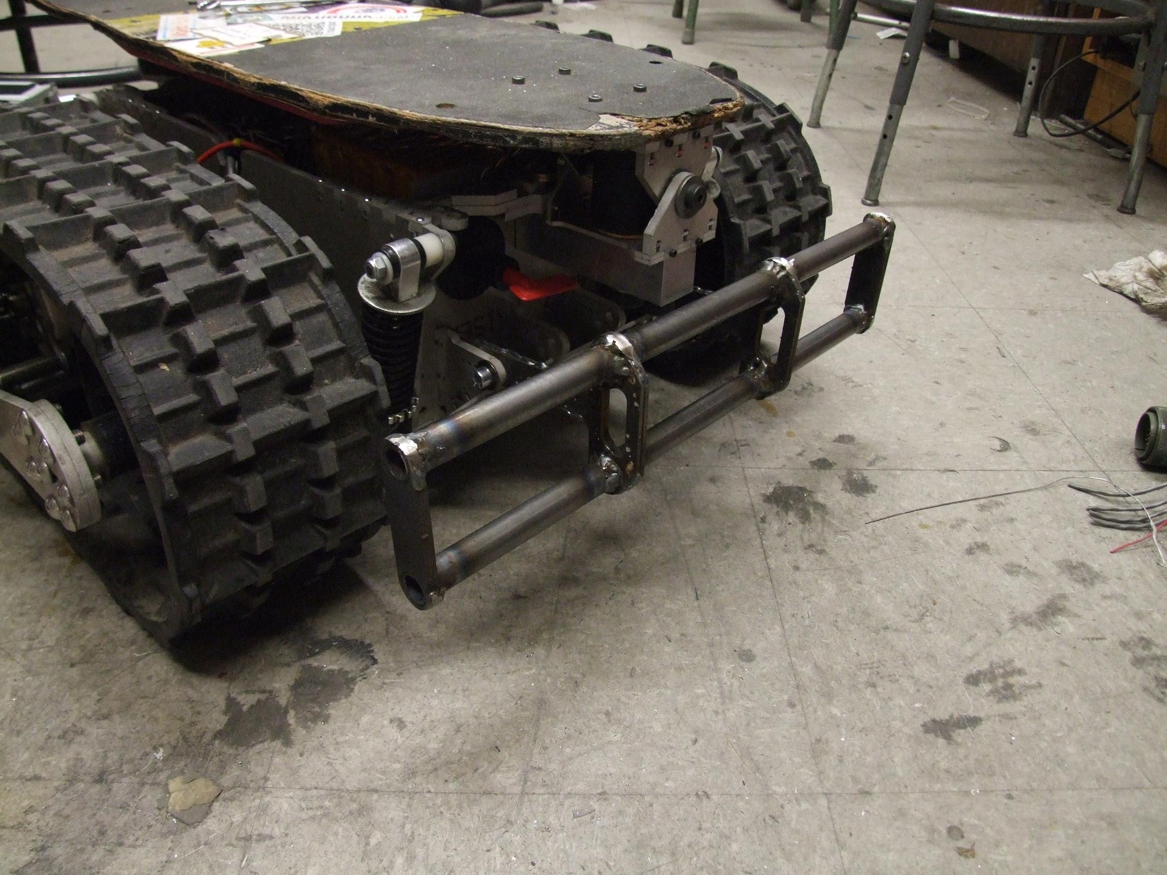
I decided that LBS would look much better with a huge crash bar on the front.
It’s not entirely decorative, however: these assemblies protect the load cells from taking direct impacts if I run into something, fall off, or wheelie/stoppie. There is a complementary but smaller assembly that goes on the back, which I have yet to gorilla weld up.
But doesn’t that look badass?