


I got some flat motors the other day.
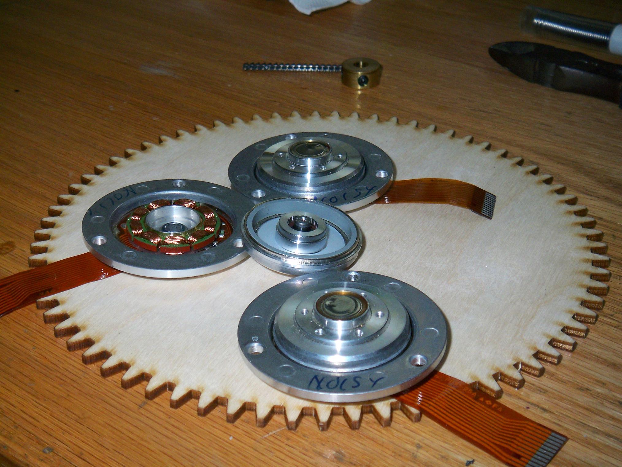
They’re seriously flat motors.
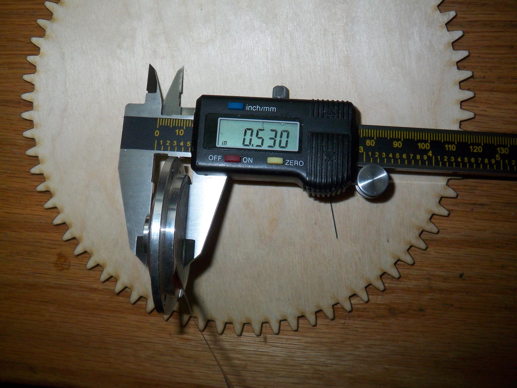
For a really flat robot.

It’s been a while since I’ve updated Pop Quiz, which has been in much the same form since the end of 2005. That makes it my longest-lived bot ever!
For revision 2, the blade height will be dropped from 0.8″ to a bit over 0.6″. The chassis height will be lowered from 0.5″ to 0.375″.
This requires extensive customization on almost all levels. The only stock gearmotors I can use are Sanyo micromotors, which are about .380″ tall, but unless combined with an additional gearup on the output, will not offer satisfactory speed.
So I’m going a different way.

This is a custom 3:1 gearbox design for a Mabuchi slot car motor, the square kind. I got a bag of 30 of these surplus a little while back.
3:1 straight off these motors at 14 volts will make the bot travel over 9000 miles per hour. However, I plan to inject some big N50 magnets in place of the ceramic ones in there now, greatly increasing the magnetic flux within the core and hopefully dropping the voltage constant enough such that 3:1 is actually sort of manageable, especially with wheels 0.5″ in diameter. The target speed is about 4 feet a second, which is incredibly zippy, but only if it works out. Extensive testing of this setup will occur.
The gears are metric module 0.4 things from SDP-SI, which is about 64 pitch. Aligning them will be such a royal pain in the ass that I don’t want to think about it at the moment.
The housing is a chunk of aluminum channel or rectangular tube, machined to taste. Four modules will be made for 4 wheel drive. Each module should be around 2/3 ounce according to Inventor.
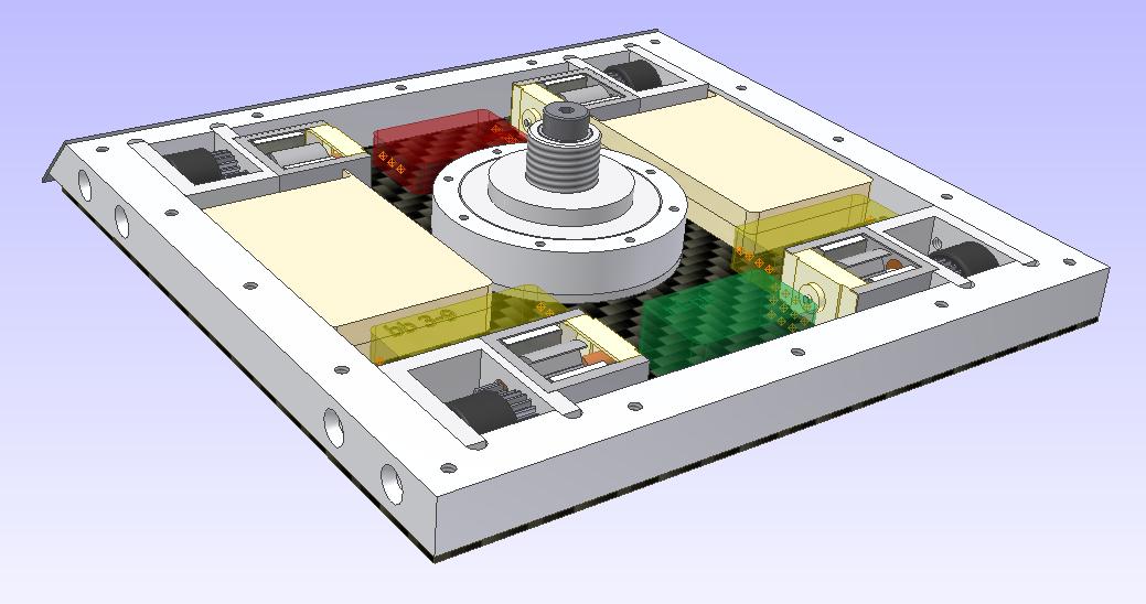
Wepon motor in place. Oddly enough, the version of PQ’s motor that worked unquestionably the best was the original hacked hard drive motor with its 2504 stator and ball bearings! The later custom motors just never quite matched up to it. So I’ll be using a HDD stator again in a custom housing, with ball bearings – no more of this bushing crap that plagued the current weapon motor.
The axial flux one had ball bearings, but didn’t fare any better because its torque output was so low.
The flat motor stators in the picture are 28mm diameter x 3mm tall, but only 9-poled. I have another set of HDD motors which have 28mm x 4mm stators with 12 poles, allowing the use of a dLRK winding, which have been designed into the above motor.
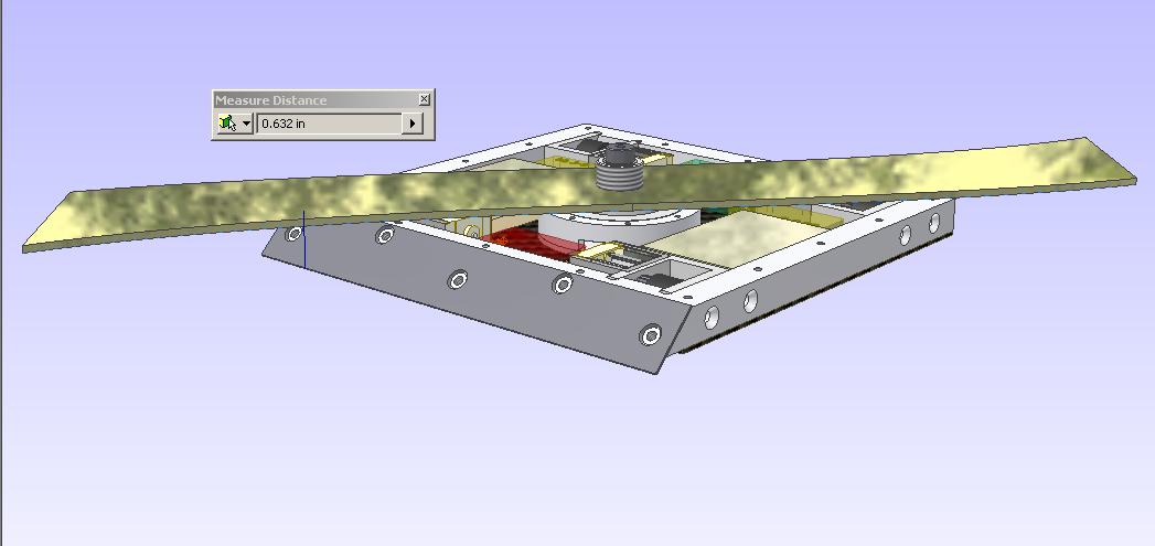
This is, of course, the fun part. Ground-to-blade height of a hair over .625″. It could be less, but running the blade to close to the body results in self-eating.
The top of the frame is exactly half an inch from the ground. The ground clearance around the wheels is a bit less than 1/8″.
Overall, the parts rundown is:
- Banebots 3-9 controllers for drive. The Scorpion Minis inside Pop Quiz at the moment are workable, but the BBs are more compact and lighter. I’m not too concerned about thermal issues with the Banebots controllers since PQ shouldn’t be doing any pushing anyway. I might revert the decision if they can’t handle the…
- Frankenmotors, former slot car motors with giant magnets attached to them. I wish they had carbon brushes.
- A GWS Pico receiver. The Cirrus 4 channel micro Rx that I use in PQ at the moment is actually too big to fit inside the frame! Spektrum makes a 2.4ghz receiver that I can use, but it is of the airplane type and does not return signals to neutral in the event of transmitter signal loss. Even though PQ is pretty close to takeoff when running, I’d prefer it stay on the ground.
- 14.8 volts of 430mAh lithium polymer cells, rated for 10-15C. I want to run high voltage, low current this time around, so 6 amps should be plenty (14.8v and 6 amps is still a solid 80+ watts!)
- A random 10 amp controller from United Hobbies. The ESC I have in PQ at the moment is 10 amps, but this one can run 4 cells. I bet it’s not as plushy as they make it out to be.
- A 12 inch waterjet-cut titanium blade.
- Lots of carbon fiber! Instead of using heavy 1/16″ fiberglass (Garolite) plates, I wanted to see if the lighter, stiffer carbon fiber material can be used in slightly thinner section (.041″). The weapon motor is supported from both sides this time, so I can probably run .021″ material on the bottom to increase clearance.
More to come! This is a summer project, since my attention is focused on the scooter and … classes (yeah, I think) at the moment.
Bot on.


