LOLrioKart update 10: Everybody to the Back

With the front half of LOLrioKart done for now, it was time to work on the powertrain. I don’t have a plan yet for the pedals, levers, knobs, and switches in the front. This includes the all-important front brakes, which I have to figure cable logistics for. I will return to them after all four wheels are connected to something that is (or will be) controllable.

Since UPS seems to have taken off early today, I wasn’t able to get the parts needed to fully finish everything that I wanted. Such a shame, because with a few hours of rigging, I could have wired the motor up and went on a (linear, fast, most likely very short) test run.

Let’s begin.
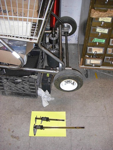
Measuring out the back end

With my new 12 inch digital calipers!!!!, I measured the center distances between three critical points. First, from the rear axle to the shopping cart’s rear horizontal undercarriage tube.. Second, from said frame tube to the bottom rear basket support tube. And lastly, from said rear basket support tube to the rear axle.

Since I knew the side lengths of this triangle, all the necessary angles could be solved for.

Here’s a cool trick if you ever need to find the center distance between two rods or two holes, and don’t have a convenient handy-dandy centerline gauge handy.

Measure straight around the outside of the rods, or the farthest points on the bores.  Measure again between the insides of the rods (with the ID side of your caliper), or the closest-together points on the bores. Add these two distances and divide by two.

Sure, experienced machinists are probably giggling over this, but it was one of those COOOOOOOOOOOOOOOOL I LERNED SUMFIN moment for me. No more eyeballing.

With critical dimensions determined, it was time to buy a few Jolts and 5am-engineer something (Like I resolved never to do again.)
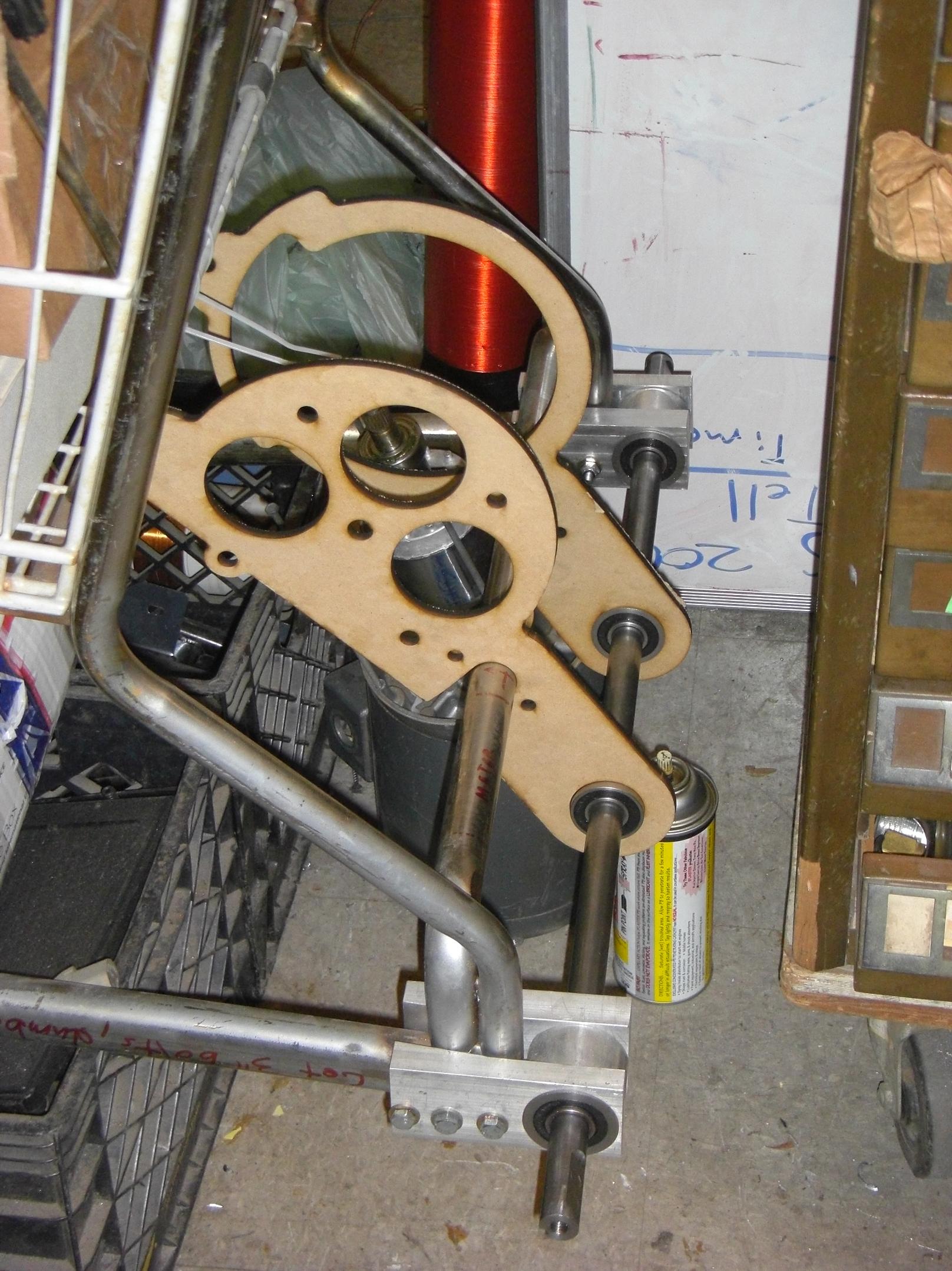
Wooden laser-cut prototype

The proper thing to do with any new design, especially one of questionable workability, is to prototype and proof the concept. Prototyping allows a more concrete observation, and subsequent interpretation, of your idea. Usually, prototyping is done with materials and tools immediately available.

Luckily for me, that happened to be leftover 1/4″ MDF and a giant lazer. I whipped up this 1:1 scale mockup of the motor-and-differential mount to see if my dimensions were actually correct. I did the same thing for NK5 before Dragon Con. It’s handy to prototype with a low-valued material, so you don’t bust money setting a flawed design in stone….
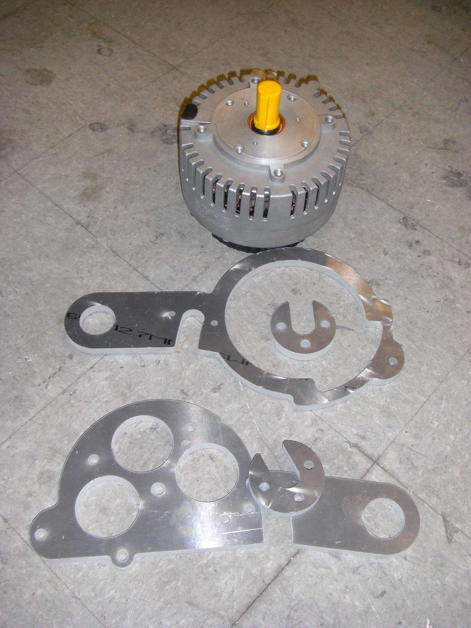
MDF to aluminum like boyz II men.

… or 1/2″ 6061 aluminum plate. After making sure the Etek actually sat in the mount and the mount actually sat on the kart (and by extension, the Etek on the kart), I headed back to the Media Lab with a half inch aluminum plate.

Only around MIT would you see someone sprinting down the street with a 3 foot long slab of metal. Nobody was decapitated in the process. An hour (40 minutes of which was trying to jiggle the 2D outline file such that it would actually cut properly – I blame the 5-year-old layout software) later, I had the semi-final, waterjet-cut parts. Semi-final because they still needed…
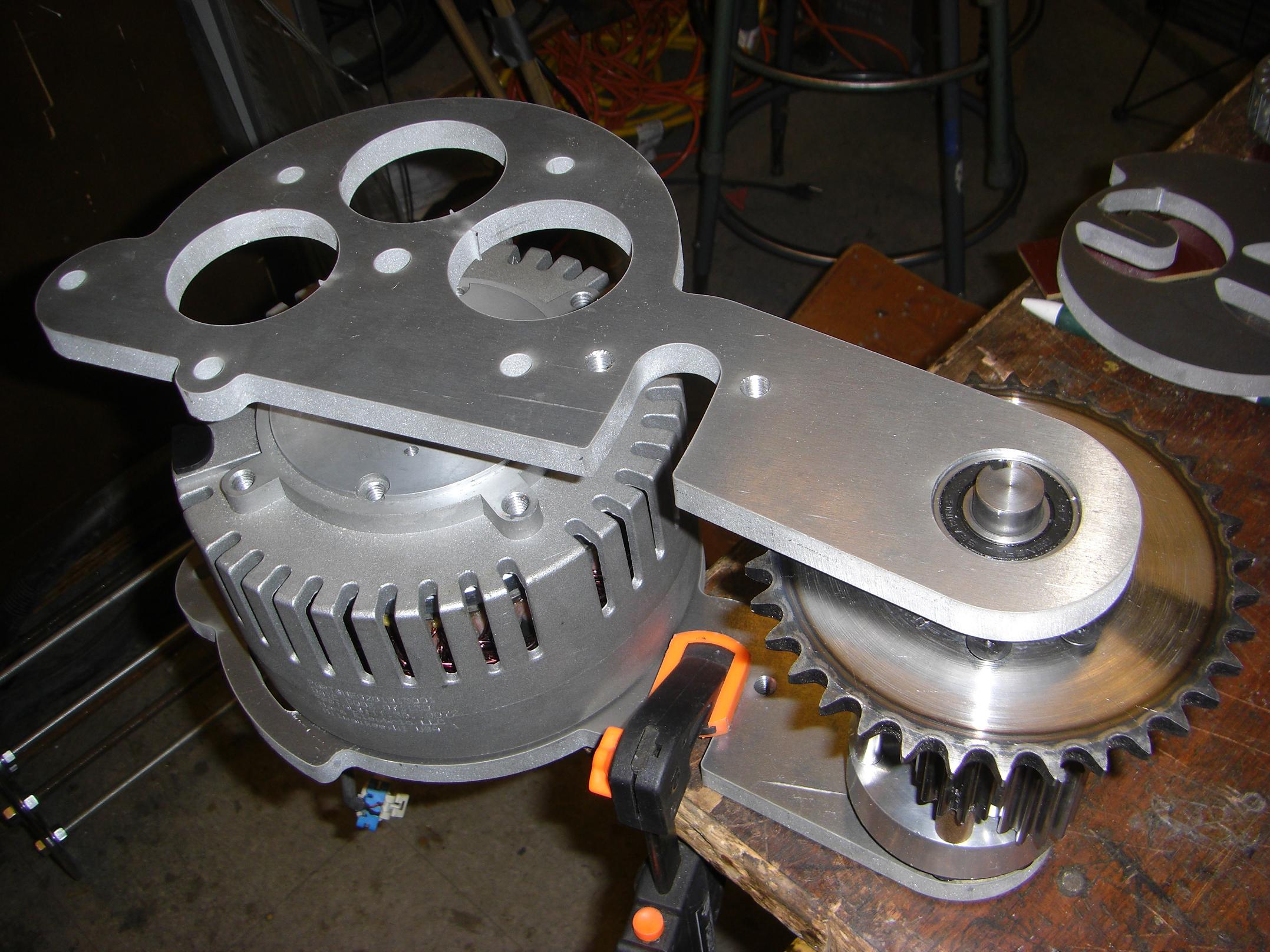
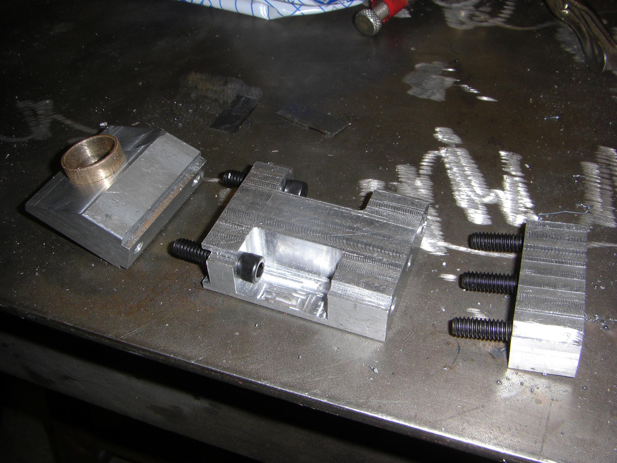
Putting parts next to eachother to test the fit

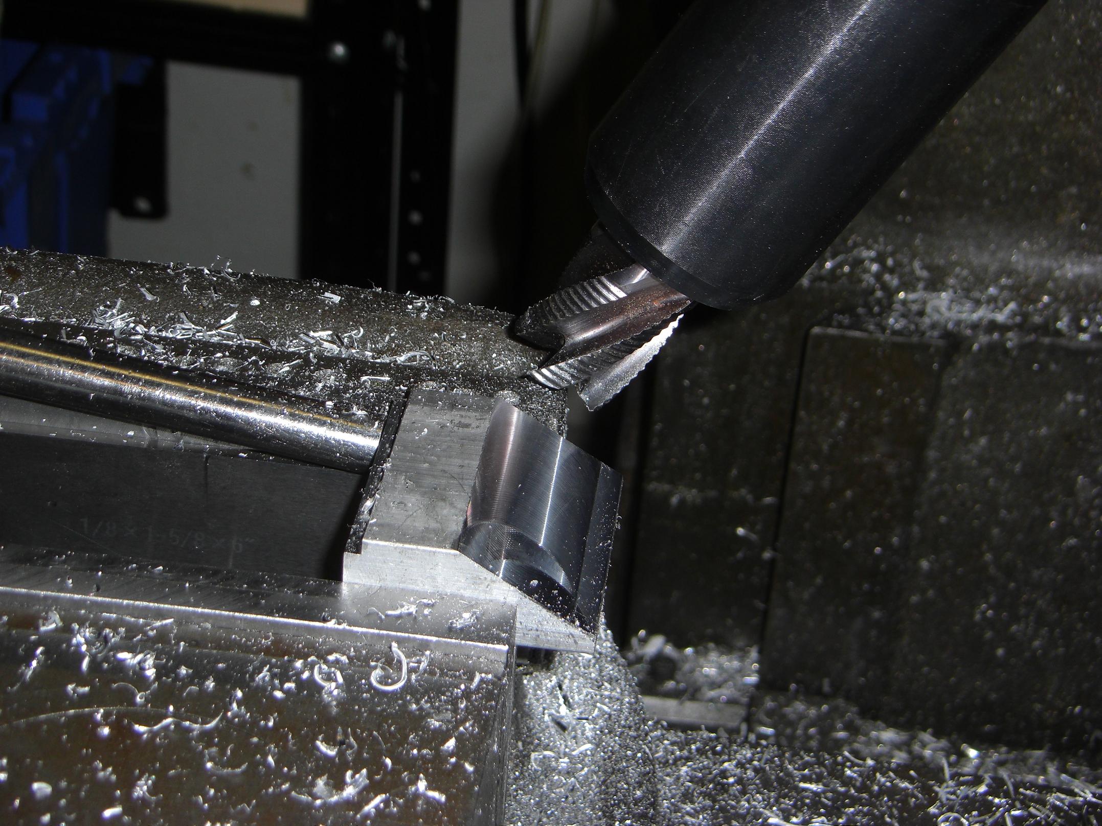
Threading, boring, and related secondary operations. Here’s everything thrown together as a visual. I used the boring head on the mill to clean up the bearing pockets. Some mounting holes were threaded 3/8″-16.

Also, I had to toss the rear mount back on the mill to add and/or lengthen some cutouts because I miscalculated the placement of some Etek features by a few degrees of rotation. Too lazy to drag the 200+ pound full size rotary table onto the mill, and not having a big enough head for the dividing fixture, I just manually interpolated a circular pocket.

It worked pretty okay.

Okay, so what’s the deal with those weird cutouts right next to the motor? I’m not seriously hanging a 25 pound high performance motor capable of gear-stripping, chain-breaking, shaft-shearing torque with a high-inertia steel disc rotor from a narrow cross-section of a material with a finite stress cycle life, am I?
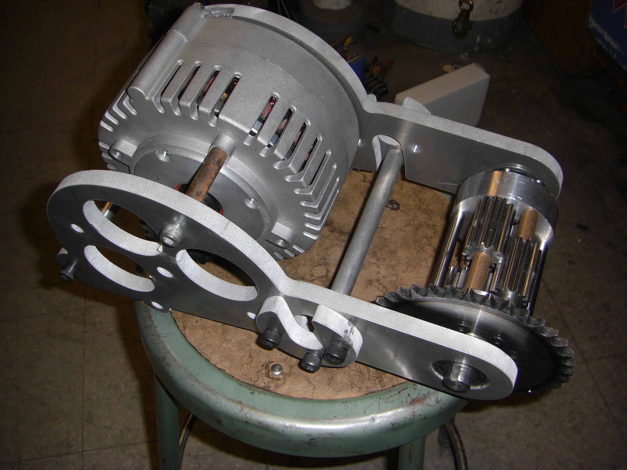
Test assembling the transaxle.

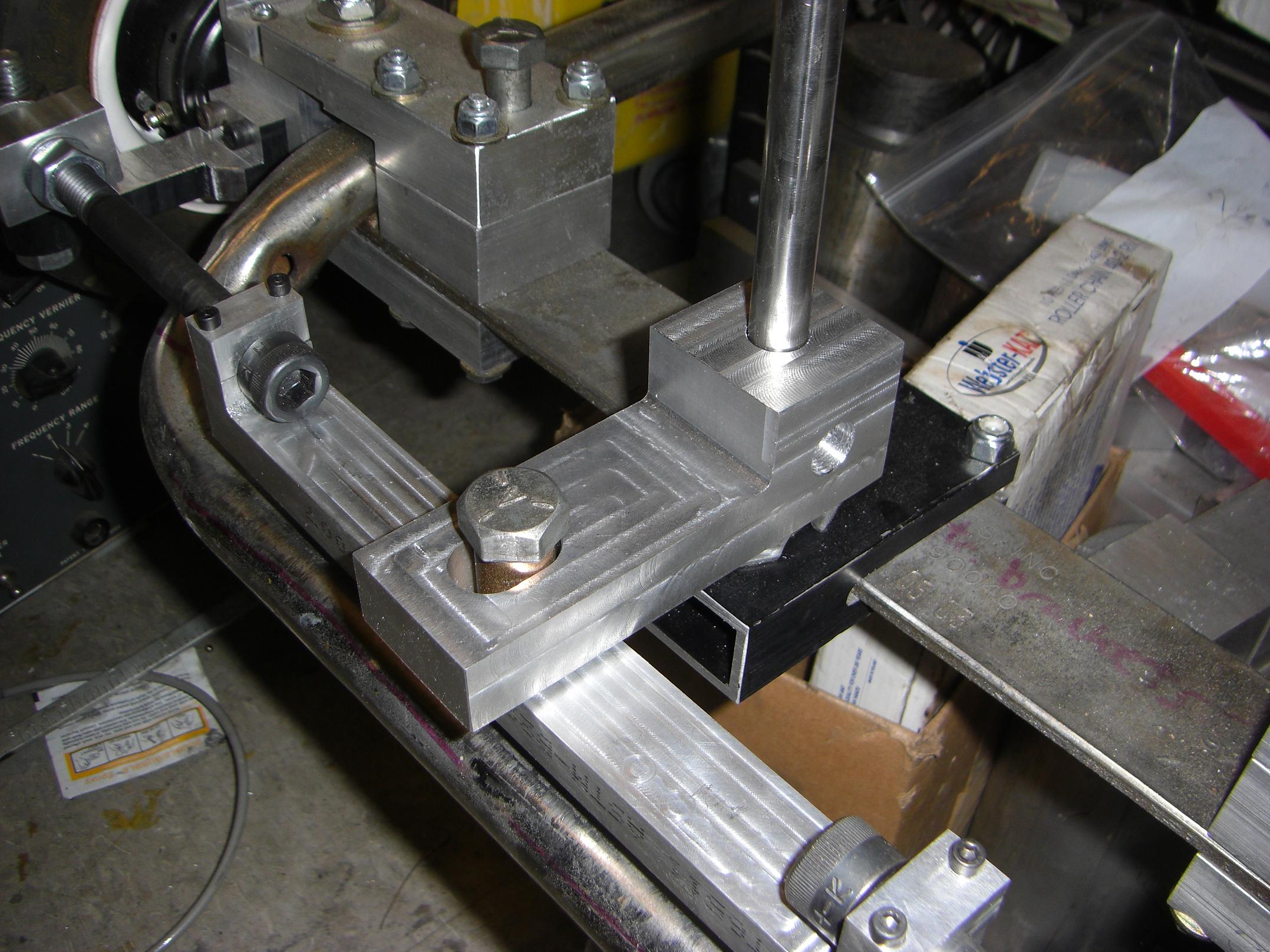
That’s where those little Pac-man things come in. Here’s the whole transaxle test-assembled with hardware I found lying around. The Etek is indeed hanging on by one screw.

It is a well known fact that two objects cannot physically occupy the same volume in three dimensions. Since we happen to live in a (mostly) 3D world, I couldn’t actually install this transaxle onto the kart if the cutout wasn’t present (i.e. there was only a hole the diameter of the frame tubing) because it would involve passing it through the tube first.

Life isn’t Autodesk Inventor. So, the cutout slips over the tubing, and Pacman closes the gap from the other side. The two pieces are securely screwed together with 3/8″ cap screws. A circle of the same diameter as the frame tubing, 1″, is left in the middle. I will axially secure the transaxle on the frame tube. with some big 1″ two-piece shaft collars.
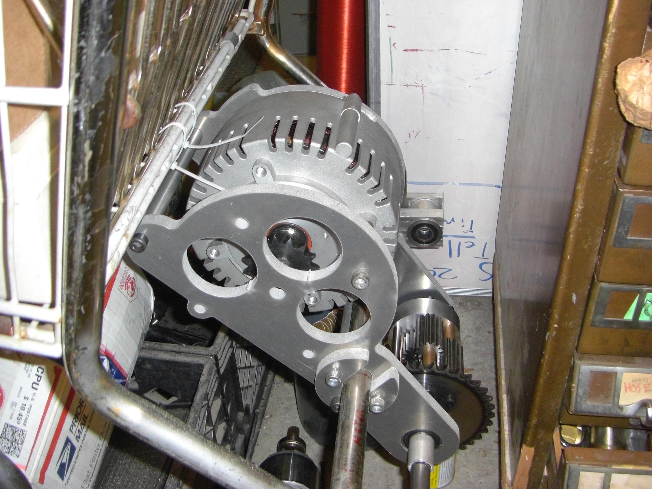
Test mounting the test-assembled transaxle.

And it’s mounted.

This whole assembly is some Serious Fucking Metalâ„¢. It weighs in somewhere north of 35 pounds, more once I make new shafts for the differential (I didn’t expect to be building something around it – oopsie) and add real hardware (including giant steel standoffs for the Etek).

The observant will notice there’s nothing attaching this assembly to the basket mounting tube. It ended up that the basket itself was welded to this tubing with enough overhang that I could not easily use it to actually mount anything pointing downwards.

Unfortunately, this meant that the rear axle itself had to become a stress-carrying member, or else the transaxle would have no means to react against moment loads (torque). Having your motor spin freely around a mounting point is no good, since that means your wheels don’t spin.

I figured loading the axle like this was okay, since no less than ten ball bearings support the axle: four in the differential, two in the metal frame, two in each outer bearing block.

Granted, they’re cheap-ass ball bearings.

Despite not being joined in the middle, the axle should be just stiff enough after the addition of two giant keyed/clamp shaft couplers to give a bit of “bounce” compliance to the motor – beneficial – but still transmit power and keep the gears straight.

Give me some slack. This isn’t going into space.

Not this version, anyway.
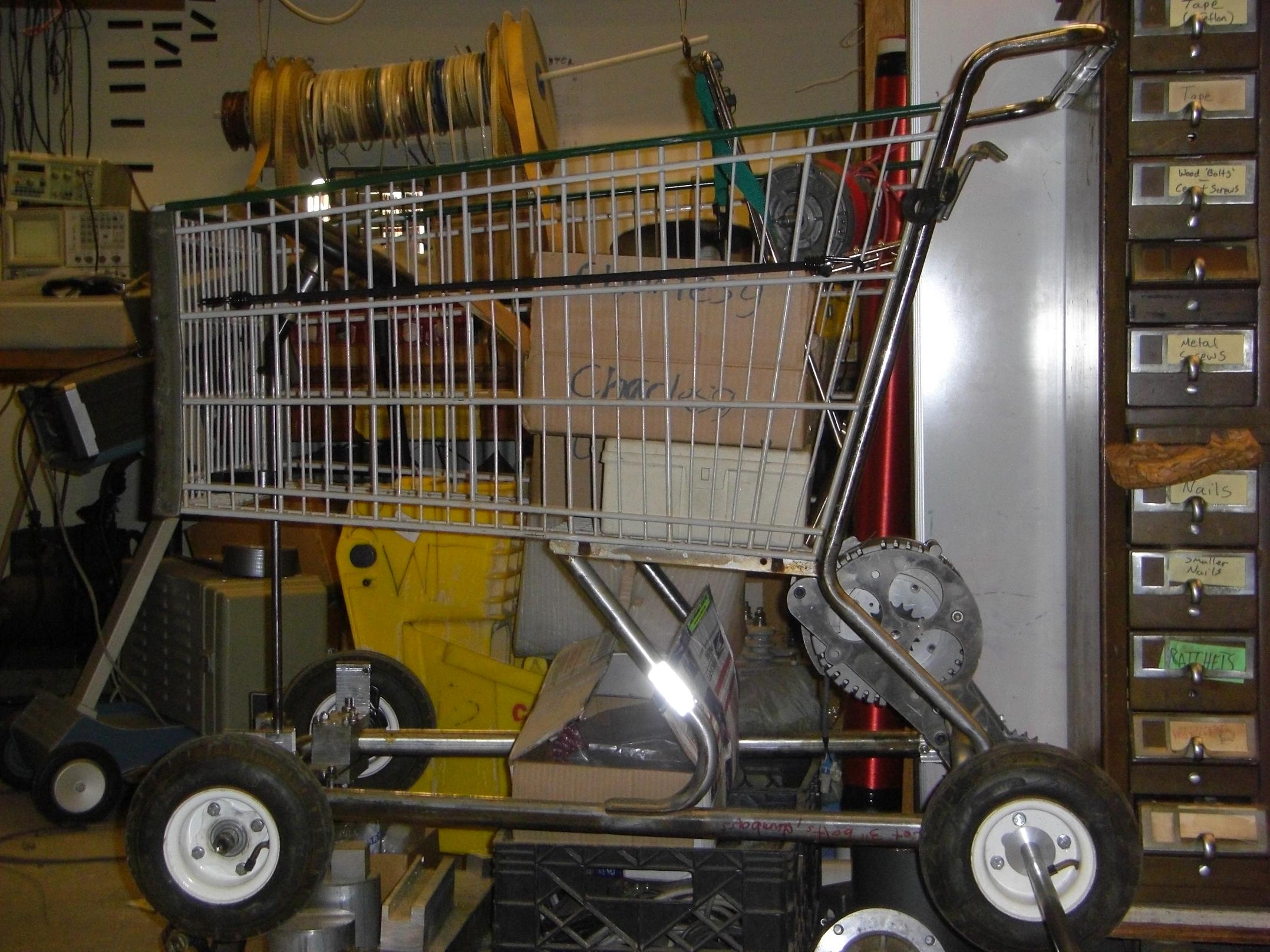
Side view of LOLrioKart with mounted transaxle

So here’s the profile of LOLriokart with transaxle installed.

Wait, couldn’t I have put the motor under the rear frame tube? It would drop my center of gravity!

Yeah, by maybe an inch. If I had put the motor closer aligned with the bottom of the frame, I would have no place to mount the batteries. The batteries combined weigh around 80 pounds, and I want them as low in the frame as possible. Currently, they fit widthwise, four packs, lined front-to-back, between the side tubes.

So what can I do without my shaft couplers, 3/4″ shaft stock, motor mounting spacers, proper-length socket-head cap screws, and other things that UPS didn’t get to me today?

BATTERY MOUNTING TRAY!

The plan is to whip up a cage that drops slightly under the bottom of the tube frame and that mounts to said tube frame. If I’m crafty, I’ll also work in a flat mounting surface for the electronics, right above the batteries.

The battery packs will need to be woken up after 8 more months of slumber (one metered in at an amazing 3 volts!).

This is the last weekend of IAP. Next week, I’ll have to start worrying about all that “preparing for the semester” bullshit.

And the week after that, 2.007 starts.
LOLriokart update 9: Meet the Flintstones Edition

It steers.

The differential was a short distraction project before I left for Atlanta.  I didn’t *really* need it, but it was a neat thought experiment that would contribute to the vehicle if I had it. What’s more essential to the vehicle’s handling is the steering system, which I’ve sort of halfheartedly been working on for the past while.

So over the last few days, I summoned the effort to finish said steering system. Another pound and a half of aluminum billet later…

i accidentally the hallway, but the steering linkages work.

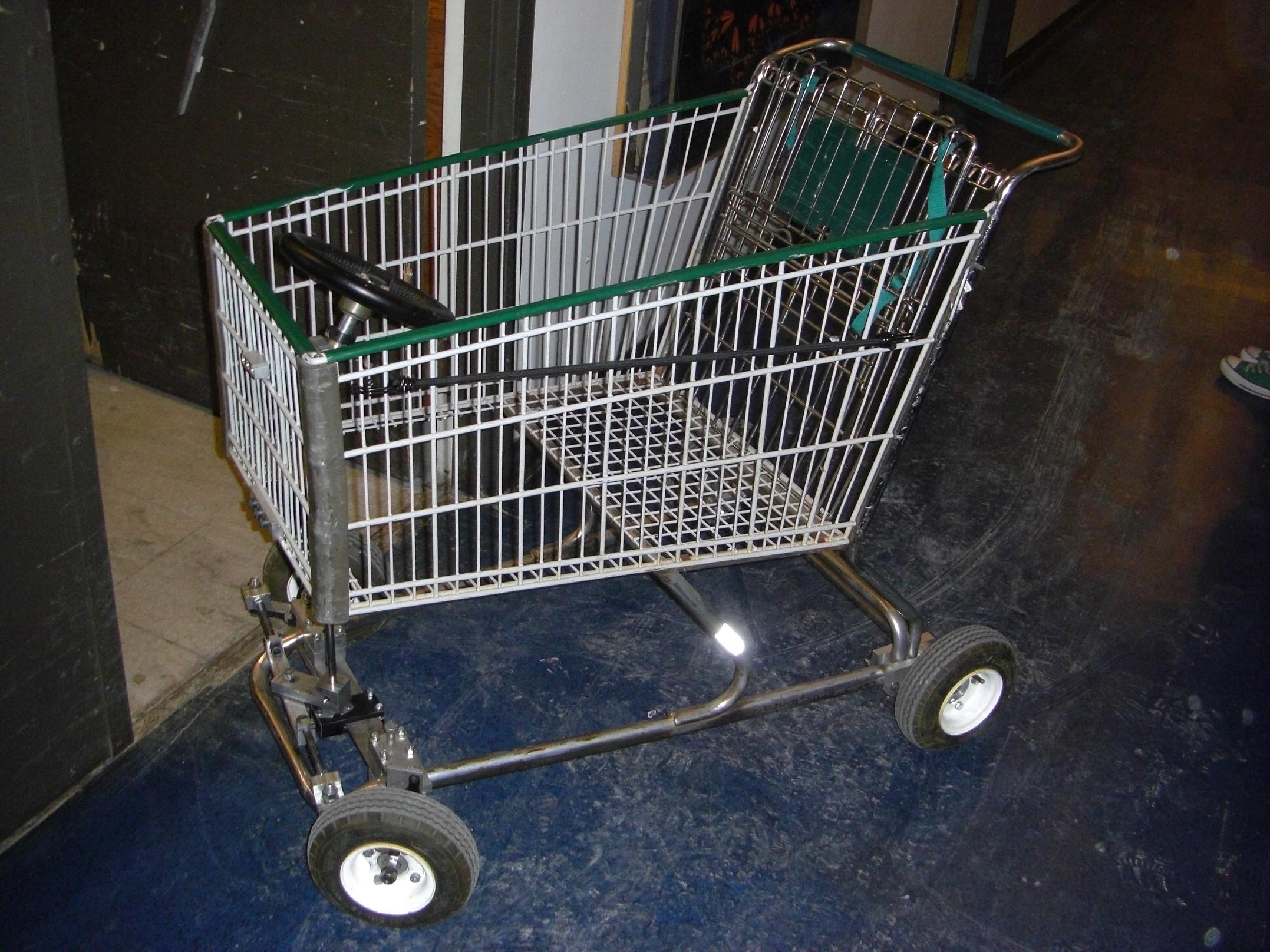
It works! Because now the driver has a controllable degree of freedom, everyone in MITERS at the time took turns pushing/being pushed through the hallways. LOLrioKart is a big hit, even before it moves under its own power…

So here’s how it was done.

Steering connecting link

MORE BILLET! Here, the cap screw linkages have been joined. This 10″ long, half inch thick span of aluminum holds the cap screw heads in clamps at the ends, and has provisions for the Pitman link pivot pin in the middle.  The cap screw sit in semicircular cutouts made by a ball-ended mill. To lock the linkages where they are, the clamps are tightened down. If I ever need to adjust the toe angle, I can loosen the clamps, turn the cap screws in or out slightly, then relock the clamp.

Pitman arm and steering pin slide joint

One more big chunk of aluminum comprises the Pitman link itself. Notice that the pin actually travels in a slot. This is because the pivot point of the Pitman link is slightly in front of the pivot point of the wheel kingpins. Each side of this contraption is its own unequal-length 4-bar linkage. Unfortunately, I can’t have a rigid front connecting link if this is the case.

So to work around it, what would normally be a pin joint  is actually a slot. This means the steering response is nonlinear, but as the wheels can only turn around 90 degrees total, the nonlinearity is small enough to be neglected. I’m not going to care about a few degrees true deviation from a linear response when I’m flying across potholes at an unhealthy speed.

Monster billet.

Completed bottom half of the steering system. That’s alot of shiny metal.

Some of my friends have expressed concern over the unhealthy amount of aluminum billet on LOLrioKart. This is often followed by giggly gossip along the lines of “He doesn’t know how to weld!”.

MITERS has a MIG welder that I have used on occasion, such as when a big crack opened up in one of the frame tubes on my bike. I don’t like welding for something like this – while it would be simpler, faster, and at this point lighter, it is just too permanent for a project whose design parameters change on a whim. It would also necessitate grinding off the chrome finish on the tube frame and adding dark, amorphous blobs of metal in its place. If I decided I didn’t like how something finished, dismounting it involves an angle grinder. Yes, I could have machined form-fitting steel pieces and welded them accordingly, but then why bother with the welding?

Aluminum goes fast on the machines anyway, and I think the disproportionately large blocks of shiny metal just give it a more unique appearance than the average tube-and-plate framed go-kart. If I had as regular access to CNC machinery, then the pieces would be significantly less blocky. For now, I’m more concerned with the functionality – I can add “features” later.

tl;dr weldin sux

Alright, the lower half is done. To the upper half!

Milling an aluminum section to a 30 degree slope

Here’s the first of 3 parts to the upper steering wheel mounting system.

To avoid having “municipal bus syndrome“, I purchased a small universal joint and aimed to mount the steering wheel at an angle no less than 30 degrees from the vertical. Fortunately for me, the universal joint only seems to operate to that point anyway.

Either way, I needed to make the angled shaft support. We don’t have an angle vise, so I had to tilt the head on the Bridgeport. I hate doing this, since returning the head to dead vertical is a painful procedure involving jiggling a dial indicator. Usually I just eyeball it – works fine as long as I’m not taking massively wide facing cuts.

Bushings from Uberclocker's fork pivot find a new life...

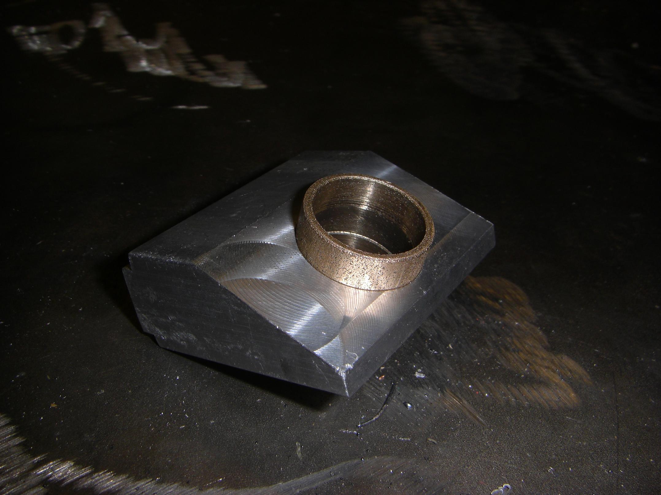
The finished part. This holds the steering column at 30 degrees. Two back-toback 3/4″ bore bushings, from Überclocker’s arm pivot before I switched to ball bearings, will support the steering column. Along with the 1″ wide bushing of the middle support and the 5/8″ self-aligning bushing on bottom half, I think I’m all set for proper shaft support.

The center spacing block of the upper steering column support.

Here’s the second of three parts. This bridges the empty space between the angled shaft support and the front of the kart basket.

By this time, I had run out of 2″ x 1″ rectangular barstock. So I had to rummage through our stuff bins in order to come up with the half-processed stock for this piece. No, the crude milling marks on top are not mine, or the litttle stairstep at the edge.

You’ll see how it all goes together shortly.

All 3 upper support parts

And the third part is done. Now it should be making more sense.

The third part just sandwiches the kart’s wire frame between it and the spacing block.

Now let’s hook up the steering wheel to all this shafting.

3/4" bolt makes a quick 3/4" axle in a pinch

I needed more 3/4″ shafting. Unfortunately, I used all of it for the rear axle and differential. Not wanting to dispose of the solid axle before I knew whether or not I was going to use it in the end, I stole a big 3/4″ bolt from the hardware bin and called it good. A trip to the bandsaw removed the threaded end and the head, leaving me with the meaty steel middle.

1" hex stock to mate with the steering wheel

Next, I made the steering wheel adaptor. The steering wheel is a quick-release type for legitimate race karts. It has a 1″ hexagonal bore, in which sit 3 balls protruding through the vertices. A spring-loaded collar keeps the balls in that position, until it is pressed, upon which the balls are free to fall outwards a bit. Normally, these balls would be shoved into a groove cut into the steering column, so that if the collar isn’t pressed, the wheel is tightly retained on the column, but can be quickly removed simply by pressing the collar and yanking.

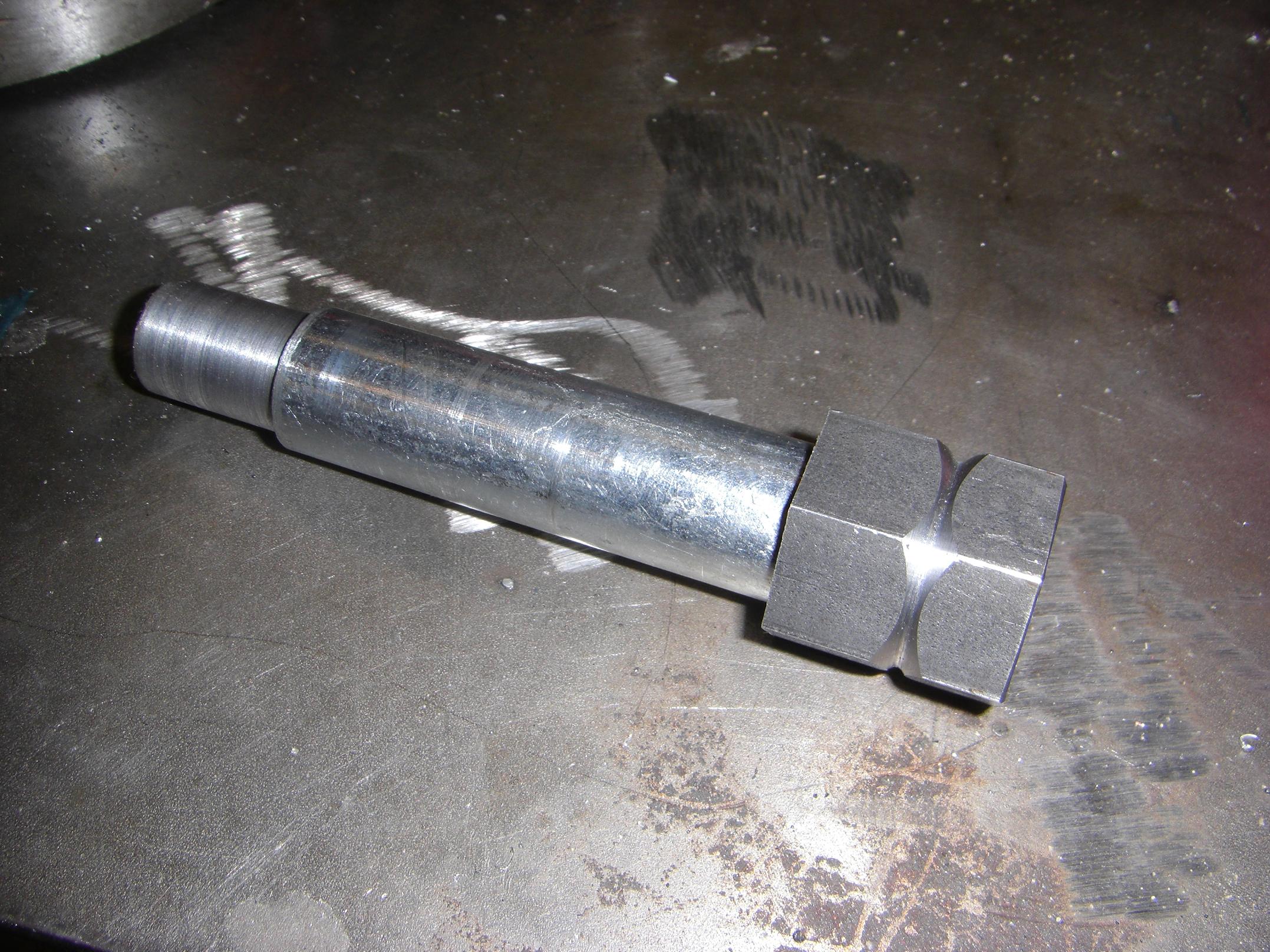
Luckily, I had a piece of 1″ hexagonal steel stock. The bore is a squish-fit (better than a press-fit!) for the 3/4″ boltshaft.

Upper steering shaft grooved and turned

Here is the hex end grooved, and the other end of the bolt turned down to fit the 5/8″ bore of the universal joint. The hex stock was squish-fitted with a 5-ton arbor press.

The upper steering shaft assembled

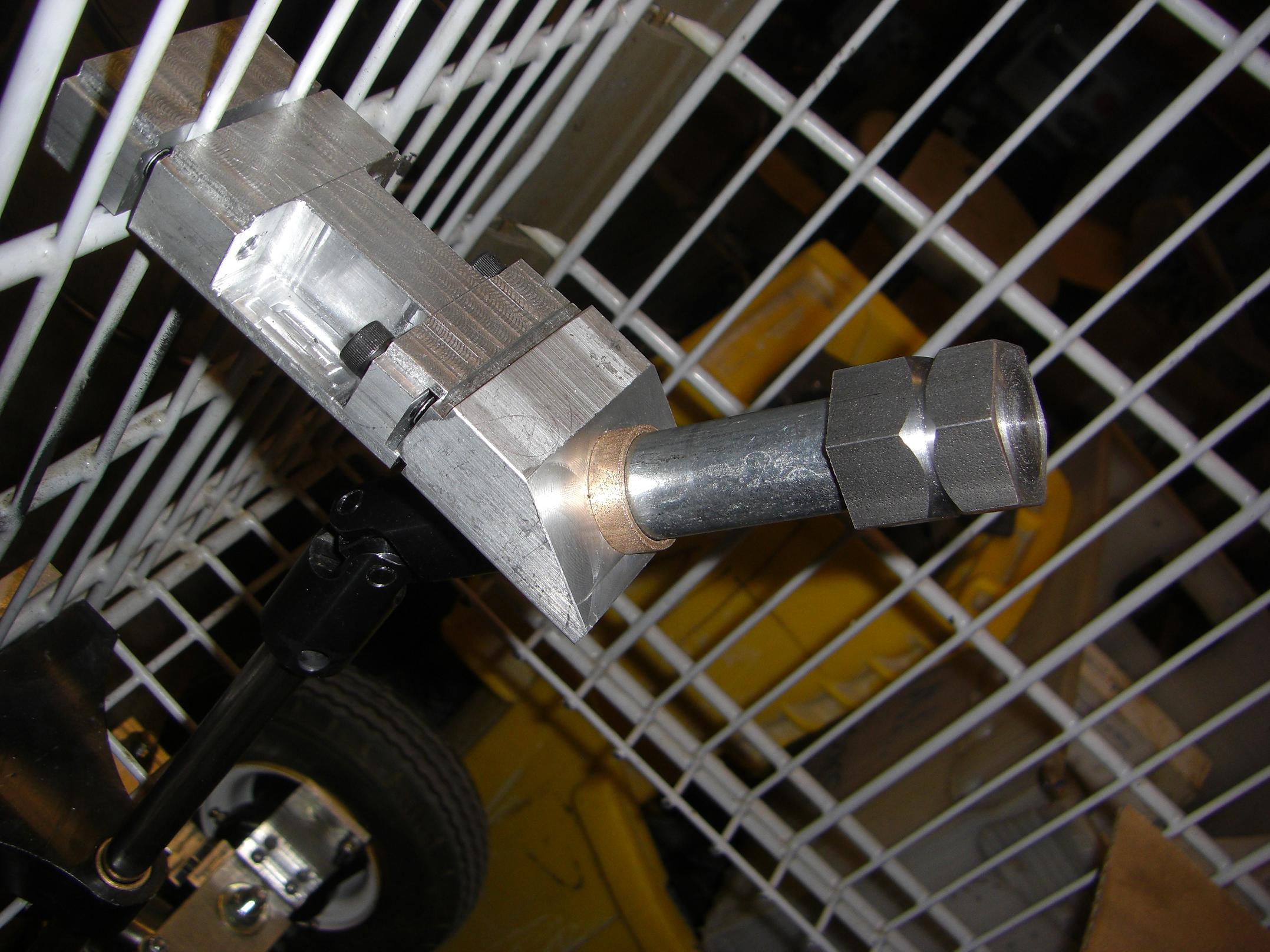
So this is how it all goes together. When the three cap screws of the shaft support are tightened, the whole assembly is rock-solid. Notice the tongue-and-goove setup on the bushing block. This was to allow for the possibility of misalignment from my eyeballing. I could insert little shims in the gap to adjust the slack this way.

Incidentally, this is the 100th LOLrioKart build pic.

Now to connect the two sides together by pinning the shafts to the universal joint.

The wrong way to fixture a bushing.

The lower shaft is 1/2″ in diameter and the universal joint takes 5/8″. The solution was a reducer bushing. Simple, but how to drill a hole in the same place in both? Optimally you’d have designed the parts beforehand to fit together.

This is how to not do it, but it worked in a pinch. I violently clamped the bushing against the shaft and stabbed a carbide 1/4″ endmill through both.

Opposite flats in the lower steering shaft to align the Pitman arm

While I had a good endmill in the mill and the steering shaft right there, I added some Flats of Set Screw Gripping (+1?). This, along with the pinned universal joint connections and the hex bore of the steering wheel, makes sure there is a fixed angular relationship between said steering wheel and the front wheels.

Steering assembly...well, assembled.

Everything put together. I couldn’t find a real pin for the universal joint, so I made do with a random standoff and a random 1/4″-20 cap screw.

On the ground, with the steering wheel.

And the steering wheel is mounted! After a check of all the set screws, it was time to rock the hallways Flintstones style.

Post-test run LOLrioKart in the N52 hallway.

I am proud to announce that, even with our reckless disregard for health and safety, the death toll from this initial human-powered run was 0.

Although there WAS a close call with someone’s dog jumping in front of the kart, necessitating a near ass-dragging emergency stop from me.