Lithium battery near-disasters and LOLrioKart shenanigans

Lesson for everyone!

1. When you charge your 120 watt-hour lithium ion polymer battery at 6 amps, please make sure your internal charge-balance wiring is not made of 24 gauge wire.

2. If they are, and you should choose to run 6 amps through them, please make sure they are not tensioned against a rough edge in your vehicle’s all-aluminum frame.

3. Should they be so situated, please at least make sure the impending insulation meltdown and dead-shorting of the lithium batteries occurs more than half an inch away from the aforementioned batteries.

If all of these failed to be true, then welcome to my life.
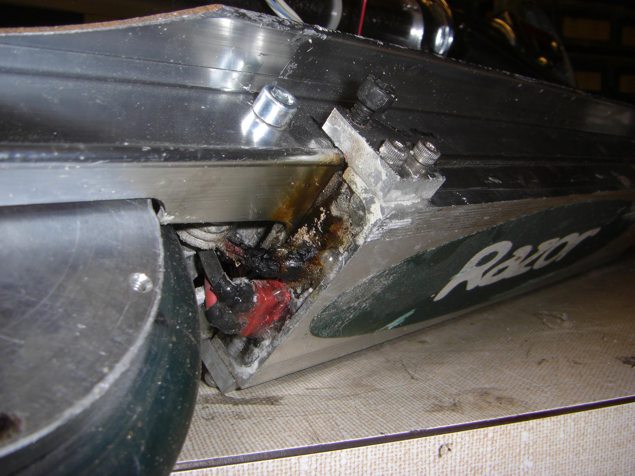
I’m glad that said 24 gauge wire burned through its plastic connector housing before Bad happened.
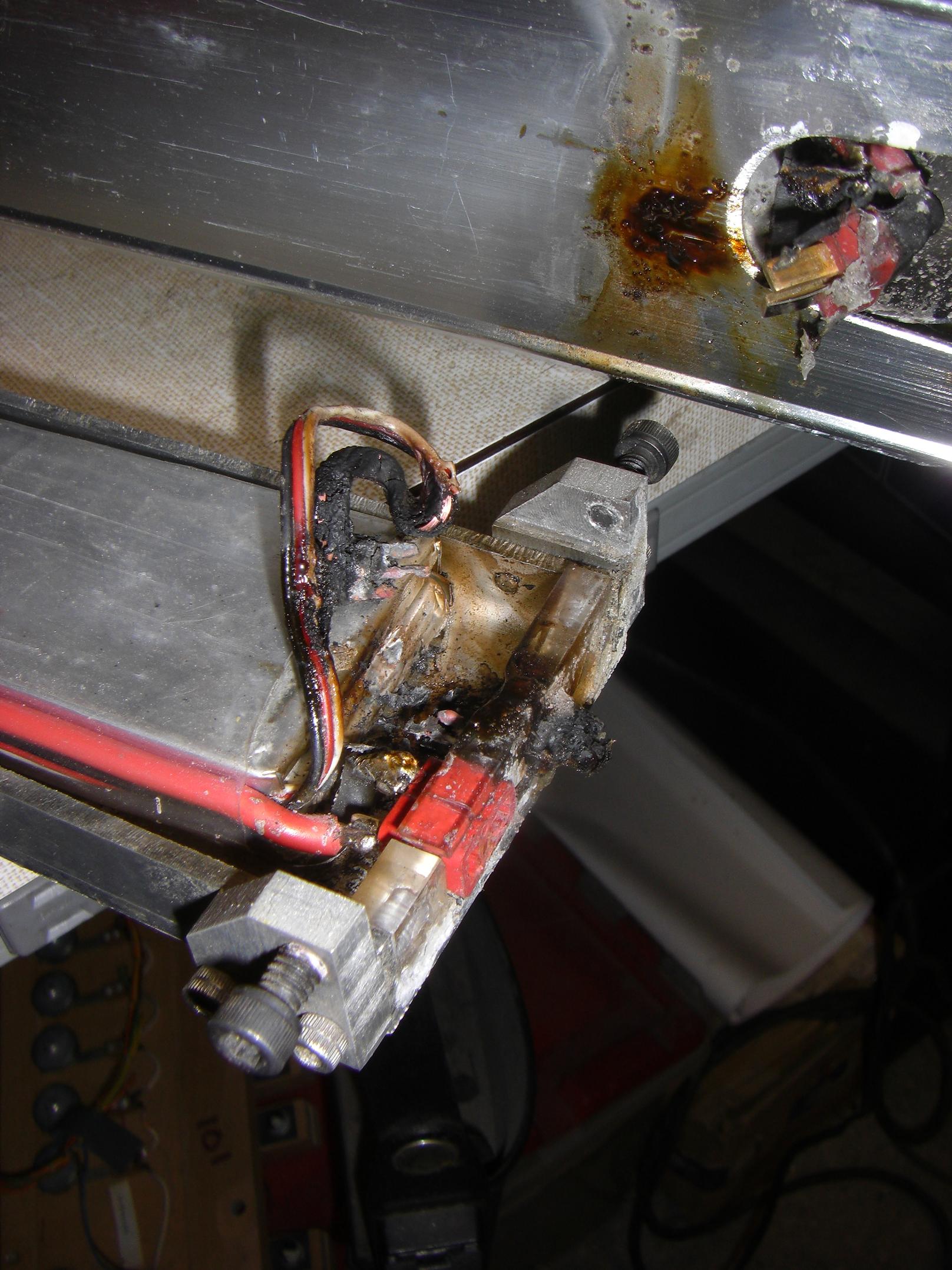
A few minutes after setting up the charge, I heard my charger beep furiously, indicating a premature charge termination (that’s what she said?).

I turn around and an enormous white smoke cloud is hovering above the scooter back end. Fearing the worst, I grab the thing, bust through the nearest non-emergency door and pitch the whole vehicle into a snow pile.

The heat was intense enough to melt the acrylic connector mounts  and completely vaporize the smaller balancing connectors. The large Deans connectors were fine, because the short occurred through the small wire.  Very fortunately I got it out of there before the ass end of the lithium cells overheated, because angry Li cells are not to be dealt with lightly.

Combine with the very close packing of the cells in the scooter chassis and it could have been.. well, more interesting.

Anyone know what the plastic is that most R/C hobby stuff and electronic casings are made of? Whatever it is, it burns leaving a hideous, acrid, obnoxious smell that can only be described as one part lifelong chain-smoker, one part wet decomposing grass clippings, and one part burnt garlic toast. It also covers the surrounding area in a sticky black oil-like substance.

And it does not ever come out of things. It’s the same stuff which they make power MOSFETs out of, apparently, since those smell just as bad.

The batteries seem to be fine, but the back two cells in the belly pack may have localized thermal damage. Since I don’t like playing lithium polymer games, I might replace those two cells. This is also an opportunity to rethink my battery strategy. The electricals of RazEr are a complete pitch-together hack made of double-sided tape, Goop, zip ties, and heatshrink.

tl;dr use thicker wire 4 batts

LOLrioKart

Over the weekend, I was using my charger to recondition some found SLAs in the great MITERS lead-acid battery pile, before the really dead ones (including 10 car batteries) were sent for disposal.

I remembered I had one of these. And this. Thus, on a whim, we haphazardly taped together a rudimentary electrical system for LOLriokart out of some of those found batteries.

It was just like the first RazEr test run – a knob with no spring return in an awkward position requiring a delicate balance of dexterity and madness to operate. Fortunately, with a 4 wheeled vehicle, no balance was required.
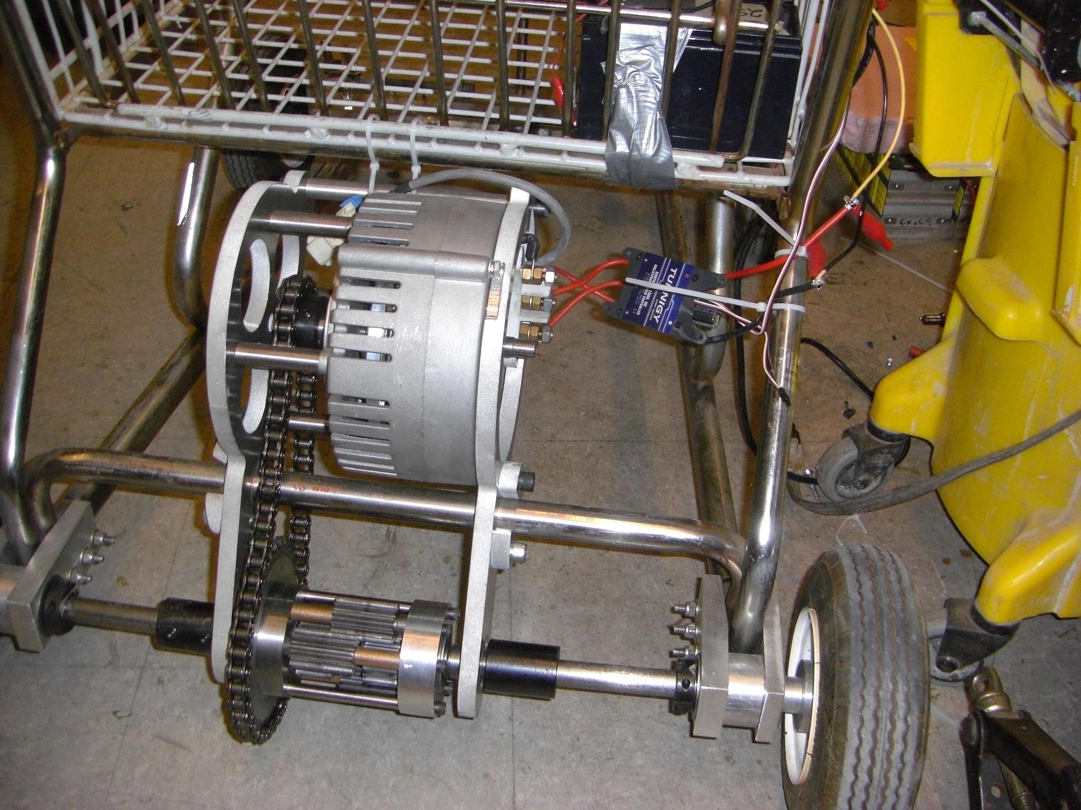
Large model airplane controller and servo tester strapped to the kart for testing...

To my surprise, the sensorless ESC was able to get the kart moving pretty adeptly. I guess that “12mhz CPU” is good for something. (Also, there’s much backlash in the chain drive, so the motor can probably move enough for the ESC to pick up the switching sequence before it hits a load.)

A test video is here.  The 24 volts of SLAs were sagging to under 18 volts loaded.  I estimate the speed at maybe 10MPH, +/- some. Still, in close quarters like the N52 hallway, it was mildly exciting. Obstacles included night janitors, that fire extinguisher, several polished wood and glass art display cabinets, and the MIT Outing Club championship canoe.

And the very well-placed panel of plywood at the end.

See? I promised I’d get the kart moving before February! I just didn’t say how moving!

When the waterjet opens again, and I get a larger sheet of aluminum to finish the battery basket, then the *REAL* fun can begin.

Speaking of the battery basket, here’s the concept.
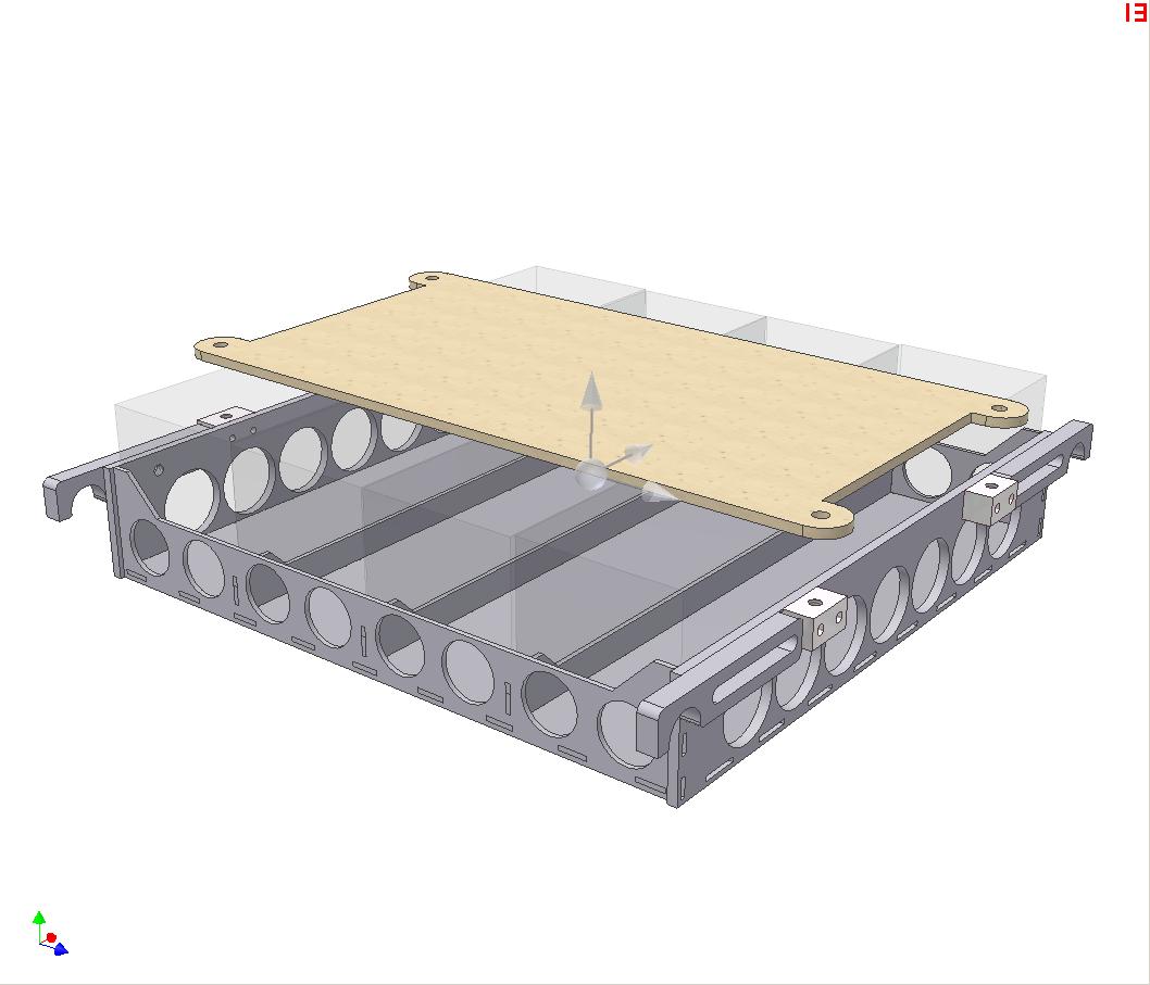
3D model of the battery basket.

Made of 1/8″ and 1/4″ thick aluminum, it will support the batteries (bounding-box outlines in clear gray) with room to add some shock-absorbing rubber or foam padding. The mounts will clip onto the chassis (bottom halves of the clamp mounts not shown), and be on adjustable-width sliding mounts. The adjustableness compensates for the fact that I don’t actually know how wide the kart, and these compliant mounts allow me to move the batteries slightly if something turns out to be in the way.

I decided to go for the 4-across mounting style just because it leaves more usable (continguous) volume under the basket.

The top plate will be made of whatever nonmetal I find when I cut everything else out. I have it spec’d out as wood, but it could be fiberglass, MDF, Lexan… etc. It will be spring-loaded to the top of the batteries by the corner mounting holes. It will also double as the electronics mount.

Combining the topic of electronics mounting and Conveniently-placed Plywood Planels of Kart-stopping (+1), and continuing my everlasting quest to engineer my way around simple and reliable solutions, I have thinking about giving LOLrioKart power brakes.

Using a beefy servo mounted on the brake mount on each front wheel,  and some interfacing with a foot pedal (you know, like a servo tester, or a microcontroller interface that also handles other vehicle auxilary functions), just use the servos to yank on the levers. With such an interface, I could actually adjust brake balance, timing, bias, and that stuff.

Wait, can’t you just run some cables? MITERS has bins full of bike brake parts I could just pull.

Yeah, but I’m lazy. I would much rather rebuild the brake mounts to include mounting provisions for a servo, then interface with the brake pedal using a clumsily-built and possibly unreliable electronic interface. It’s all the rage these days, like aluminum billet where a simple clamp-and-weld would have sufficed. Besides, since this is an incredibly bad idea to begin with, I might as well add another layer of bad-idea.

(It is indeed easier, faster, and better to route two Bowden cables – don’t get me wrong.)

Work on LOLrioKart will probably taper off a bit as the semester begins.

Speaking of semester, today is Registration day (as well as Techfair), and I need to wake up before sunset.
LOLrioKart Update 11: [/drivetrain]

I got the last drivetrain parts on Tuesday afternoon. So, I guess I’m proud to announce that the power transmission side of LOLrioKart is complete!

With this, work is shifting onto the electrical system and last touches. What does this mean? You’ll probably not hear about this project for the next 8 months, of course, if the scooter build was any indication. However, the sheer level of ridiculousness this project has attained so far, coupled with my lack of usual robot projects, means I’ll most likely keep moving quickly.

Here’s some drivetrain assembly pics.

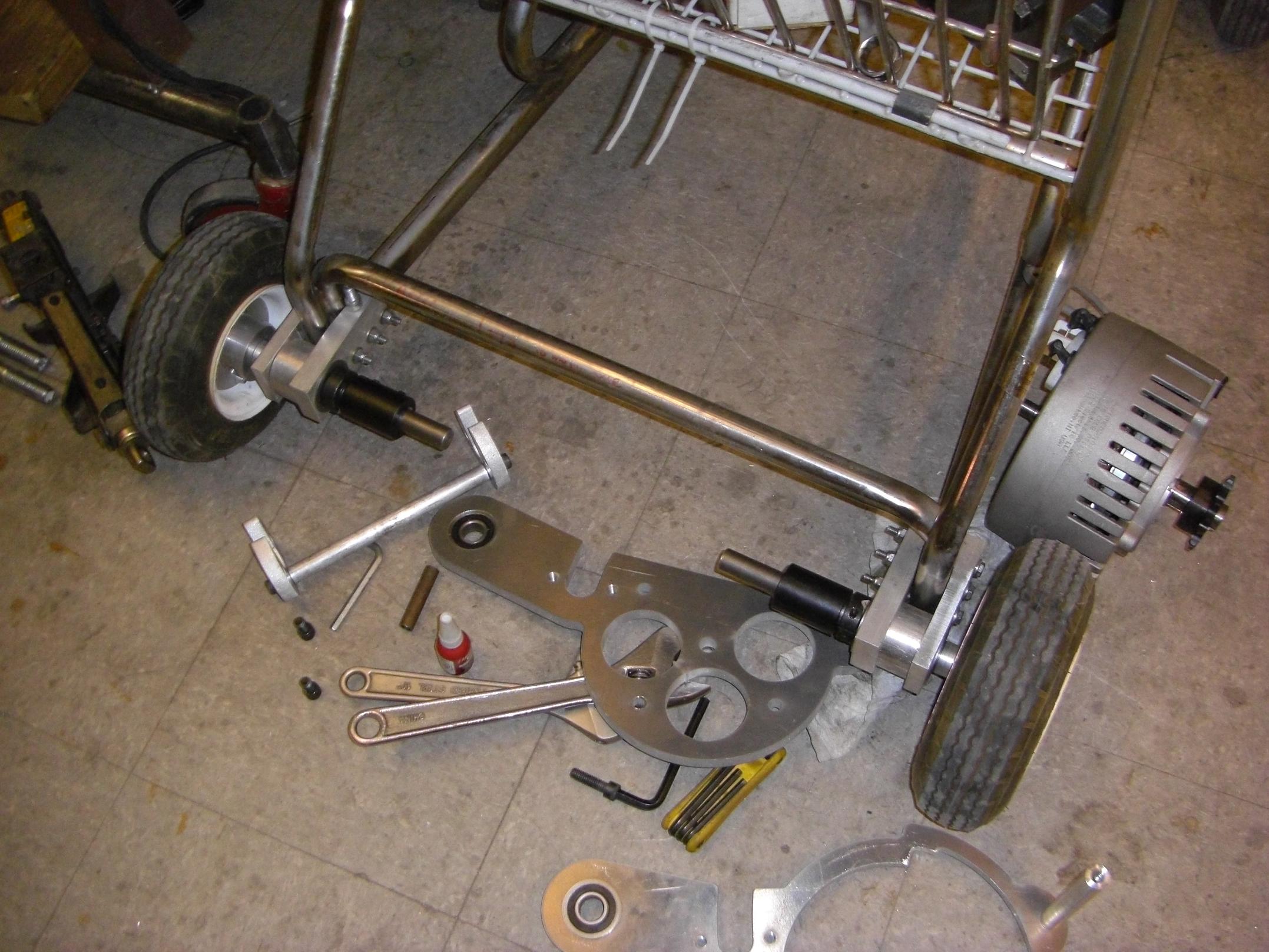
Disassembled drivetrain awaiting finalized parts

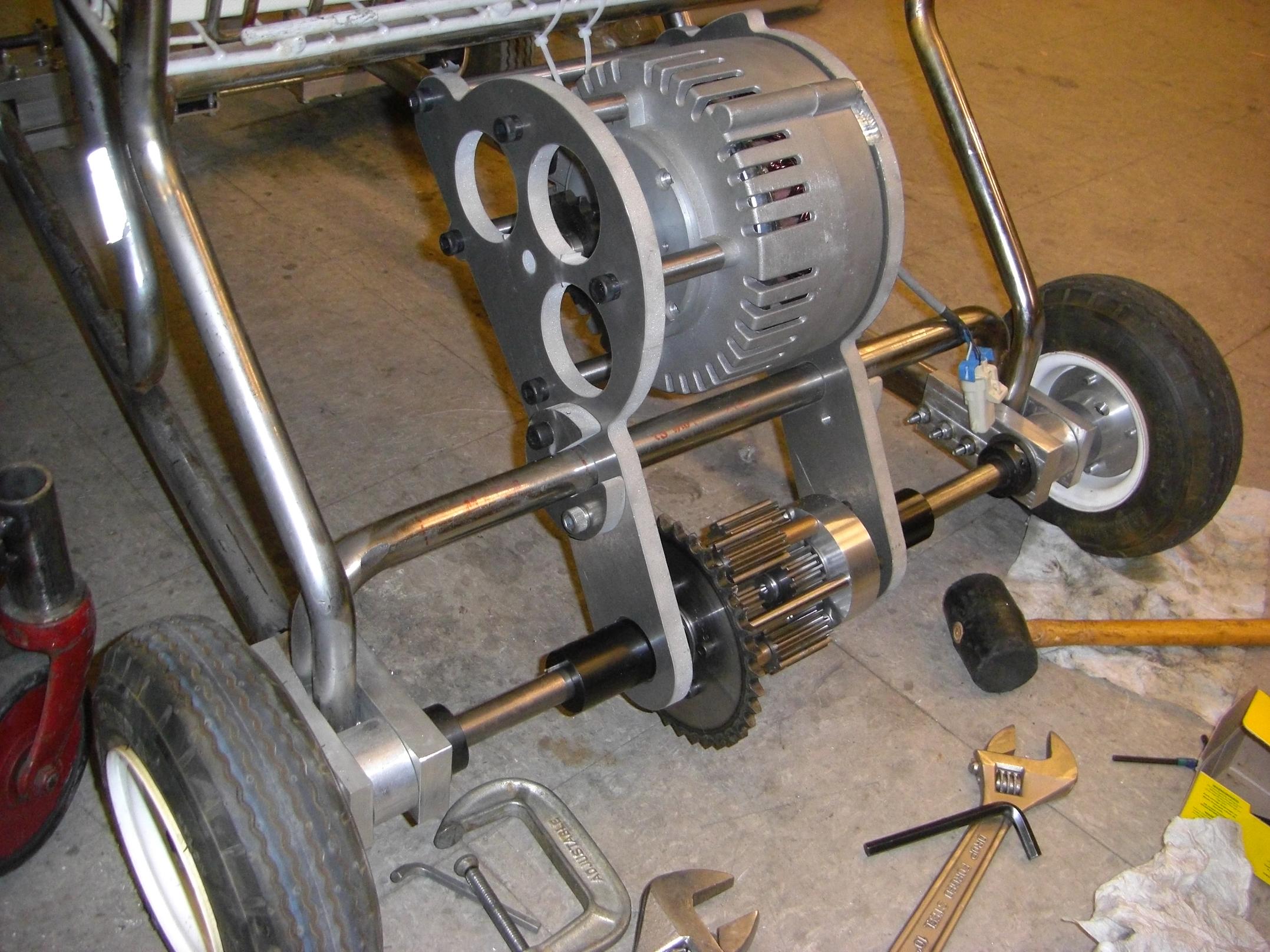
I tore down all the temporary mounting provisions to await the final parts and hardware. The bolts that temporarily retained the wheels (so we could putz around the hallways under human power) have been swapped with the actual half-shafts. I bought some 3.5″ long socket head cap screws to mount the Etek through one of the transaxle side plates. The only thing I needed to make were longer shafts for the differential so I could use shaft couplers to link them to the wheels.

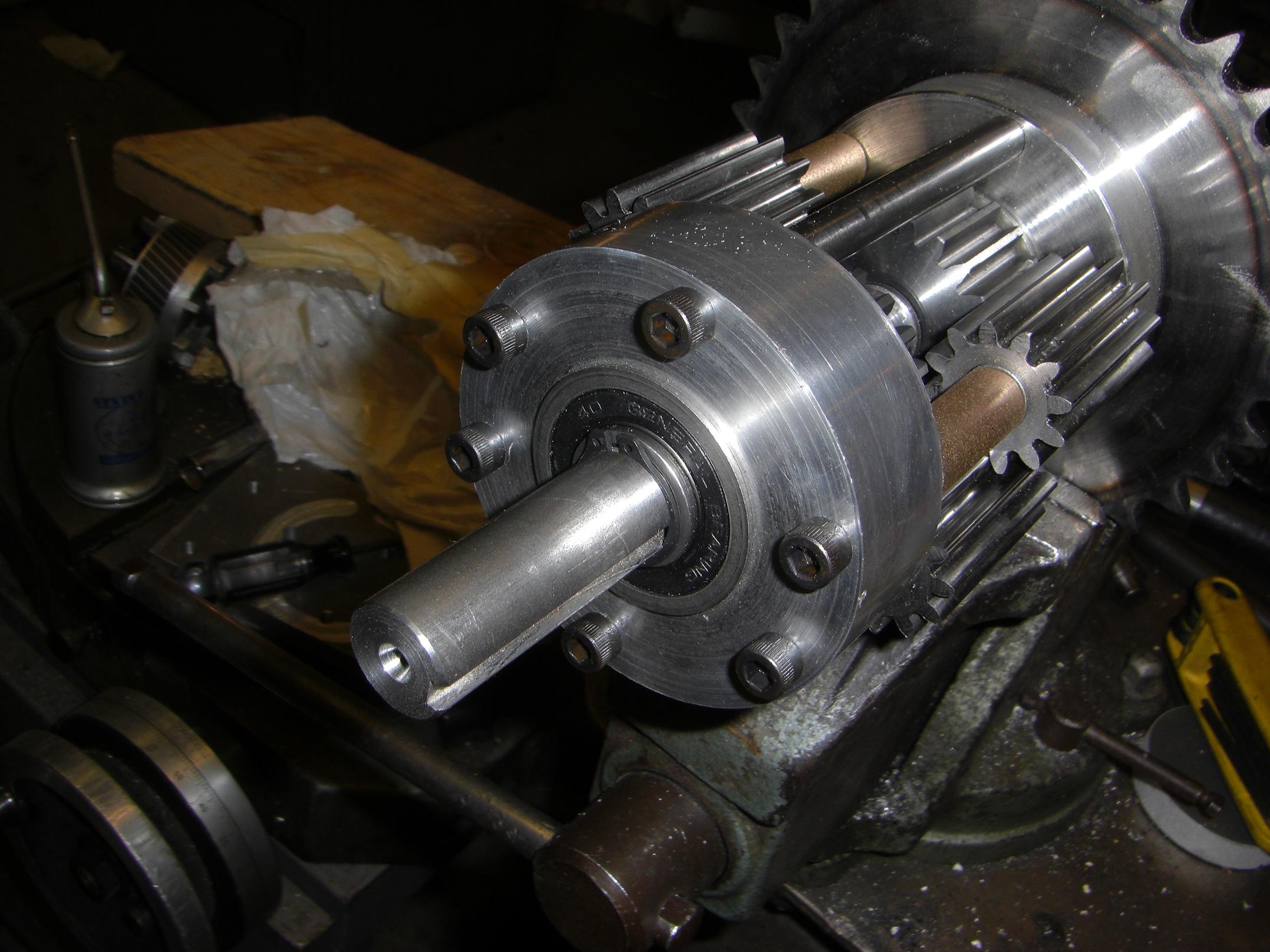
New half-shafts installed in the planetary differential

Making the longer differential shafts mostly involved taking the center shaft section left over after making the halfshafts , splitting that in two, and cutting a retaining ring groove for each half.

Unfortunately, I couldn’t find my Convenient Lathe Bit of Groove Cutting (+1?), so I had to grind one from a blank.With no proper tool grinding provisions, that was quite an interesting feat.

The shafts now poke out another inch, enough to secure the shaft couplers.

Fully assembled rear transaxle, minus chain.

Like so. With the “pacmen” secured and all collars, set screws, and whatnot tightened down, the assembly is rock solid.

The couplers are simple 3/4″ bore keyed-plus-set-screw jobbies from McMaster. A long key connects both shafts together. So, under optimal conditions, it is the keyway (not the coupler itself) that will transmit the torque. The coupler’s just there for moral support.

In a similar fashion, in a properly designed bolted joint (Gee, how many times do I actually design my bolted joints?), it’s the compressive friction force between the pieces being tightened together that transmits the load – not the bolts themselves, which are only there to provide the compressive force.

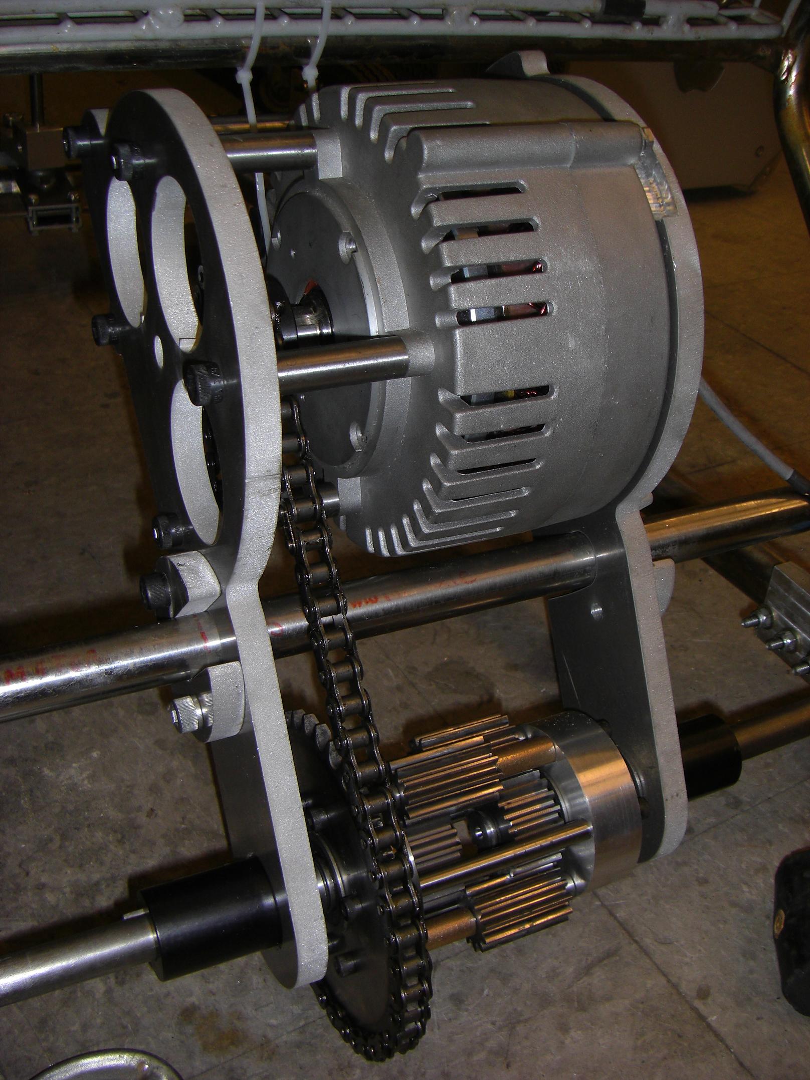
Drive chain spliced and mounted.

And the chain is mounted.

It’s a single-strand ANSI #40 setup. I didn’t expect that mounting this would be so straightforward, give that I had two odd-toothed sprockets at a non-integer inch center distance. But, to my delight, the chain length required is indeed extremely close to a whole number of links. It’s “droopy”, but not loose.

After the chain stretches from breaking in, it will probably be more on the “loose” side of things.  In a pinch, I can route the chain over one of the Etek’s lower mounting spacers, and drop a bearing or idler sprocket on said spacer.

So that rounds out the drivetrain. Well, a drivetrain isn’t any good without a power source, so onto the batteries…

Giant nickel cadmium batteries!

Here they are again, the giant nicads of last year. I have no real facilities for taking care of batteries this large. At the same time, I figured batteries this large could take quite the beating before permanent damage occured.

It’s not like they’re healthy after sitting for two or three years before sitting for 8 months, anyway.

To revive the packs again, I first applied the voltmeter on each cell. Most of the cells in each pack still showed a reading above 1.1 volts. Others, however, were pretty much zeroed.

Nickel cadmium batteries, when left sitting a long time, like to grow tiny crystalline filaments of nickel within themselves which cross the electrolyte and separating layers and poke the other electrode. This, of course, internally shorts the cell, causing rapid discharge to zero volts.

To wake those cells up again, there is a scientific process known as zapping, which uses a high voltage capacitor to momentarily dump a large current into the cell. The filaments vaporize, and the cells can be cycled again to get rid of them.

Of course, scientific processes I had not access to, so I made do with a large lead acid battery and some meaty alligator leads. A very short ‘blip’ on each cell released a shower of sparks and put some life into the cell. It was then immediately put on my peak charger to bring it to 1.2-1.3 volts.

This process took a while, since each cell had to be measured, zapped if necessary, then charged after zapping. I think I’ve been babysitting the batteries on and off for the past week.

Eventually, however, all of the cells were at a level close enough together to charge their entire respective  packs at once. This just involved setting my charger to 7 amps, its maximum current capacity, then leaving the whole thing overnight.

Yes, the building is still standing. I’d come back and see the charger stopped somewhere around 400 to 450 minutes, after the amp-hour counter had fully rolled over. This calculates out to ~40AH put into each pack. My guess is that alot of the charging current went into slightly overcharging the good cells while the weak cells caught up.

For the past two days(!), all4 packs have  been wired in parallel and the whole thing charged at 5 amps, to attempt to equalize all the packs. I had to turn off all the limits on my charger for it to run that long. The 3-digit minutes counter has rolled over several times.  Each pack is getting about 1.25 amps at this charge rate…which is like C/30. They will probably never peak.

I have no facilities for testing the discharge of cells this large, so I’m just going to lob them on the kart and drive around with a voltmeter. For now, I’ll assume they’re all in decent condition.

What’s next? Oh, designing that battery + electronics mount that I never really got to!

Test-placing the giant nickel cadmium batteries!

I’m a bit stymied by battery layout. There’s several configurations I can use, each with their upsides and downsides.

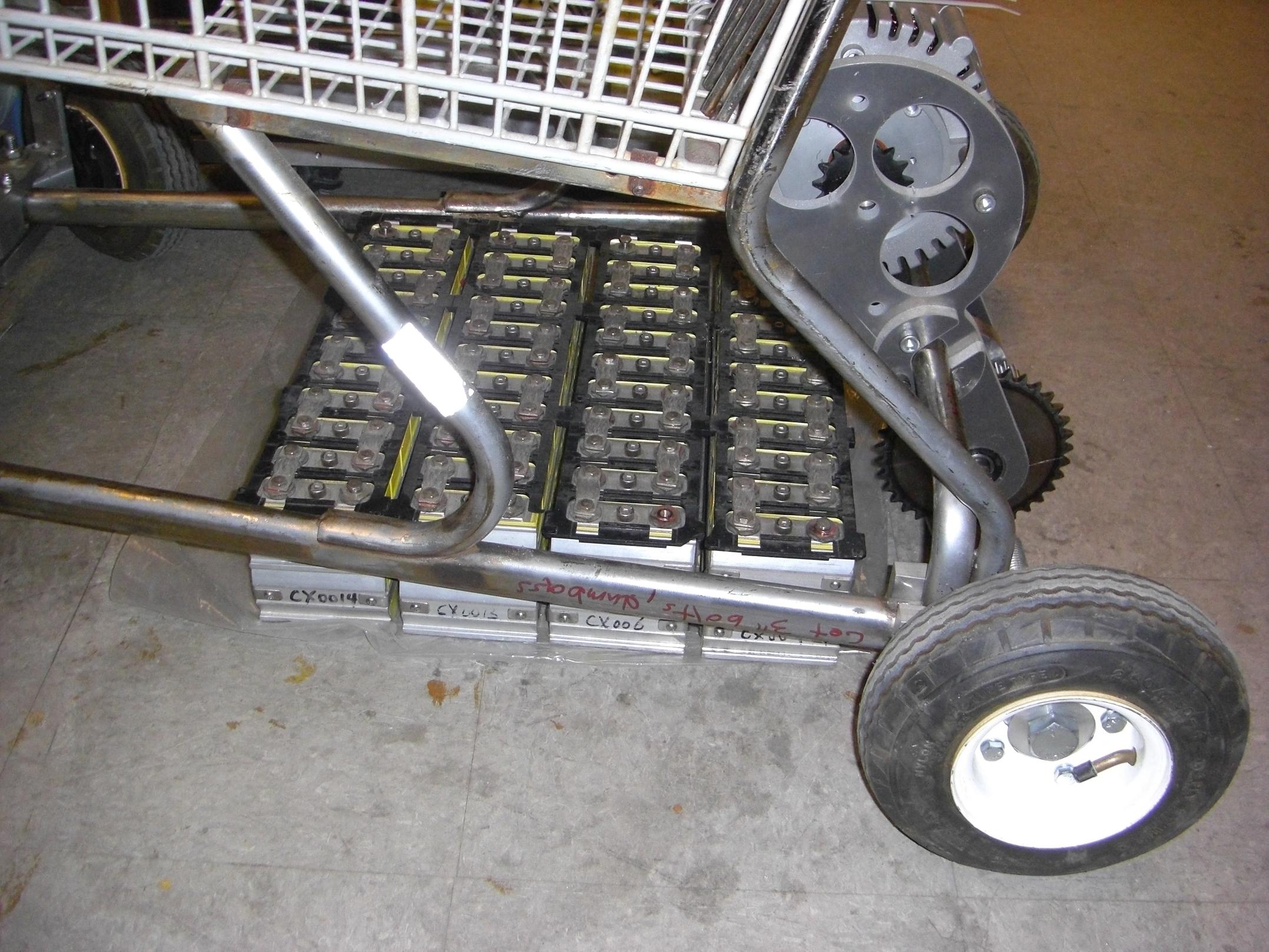
This 4-in-a-row layout gives the best possible center of gravity placement vertically, but not horizontally. It puts alot more weight on the rear wheels. With me in the basket, it will be even further back.This means I stand a much higher chance of wheelying instead of launching, and it could affect steering also (heavily rear-weight-biased vehicles tend to suffer from understeer).

Since LOLrioKart is not a real car, I’m not as bothered by this fact. The cheap handcart rims will probably bend first.

Alternate placements include a 2-by-2 layout – that is, two packs stacked on top of eachother, then two of these metapacks side-by-side. Then I can place them either transversely (as pictured) or longitudinally (down the middle). The disadvantage of any ‘stack’ packs is that I don’t have immediate access to all the battery terminals, something that I think I’ll need because of the age of the cells and their demonstrated voltage instability.

Yet another placement is a “3-by-1” T layout. I can’t fit all 4 packs longitudinally side-by-side, but I can fit 3. Then I can have a single one at the back, mounted transversely. This actually gives the most centered (good!) layout of the batteries, but I’ll have to make a T-shaped mounting basket for them, which makes that issue more complicated.

In the end, I think I’ll just go with the 4-in-a-row. It’s the simplest to design a mount for. I can build a wheelie bar or add something else up front to compensate. I have access to all the cells (electronics and wiring can actually go on the back side of the basket to keep this space clear).

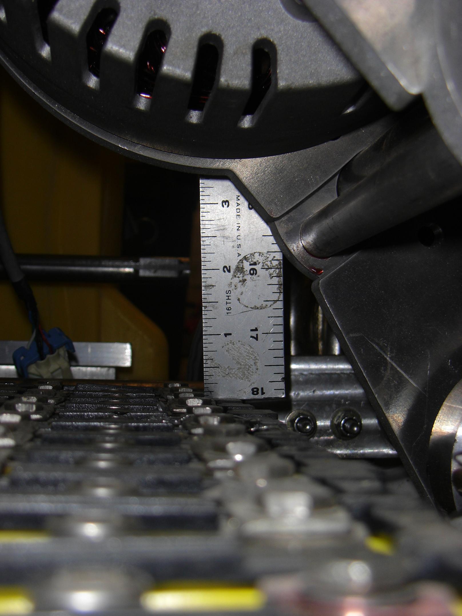
Measuring the allowed clearance between motor and battery

Another advantage of the “3 by 1″ layout is the ability to shift the whole pack forward, past the motor. Right now, I can only elevate the packs off the ground by about 2.75 inches before I hit the motor mount. This means at most, I can have 2.75 inches of ground clearance – throw in 1/4″ for the mounting provisions, and I can probably have 2.5″ of ground clearance, maximum.

Go-karts tend to be pretty low machines, so this may actually be acceptable. After all the sprocket in the back is 6″ in diameter, on 9” wheels – giving a maximum clearance at the back of 1.5 inches. The front steering brackets hang pretty low also.

But if I ever suffer from ground clearance issues, it’s always an excuse to move to bigger wheels…

Stay tuned for the next episode of Charles plays with large batteries in an inappropriate fashion!