


It’s August! That means the end of the summer build season, MIT’s Freshman Orientation, and most importantly, Dragon*Con, are all coming up soon.
In other words,
AAAAAAAAAAAAHHHHHHHHHHHHHHHH
D*C’s Robot Battles has been my annual robot party since 2002 when I first began spectating (and 2003 when I began competing). I’ve tried to go every year possible – 2007 was the big exception because my very own freshman orientation trapped me on campus then. I’ve always enjoyed the atmosphere of the event moreso than most other competitions just because it’s so not serious business. It’s a primarily sumo and show-off event because of the limited audience protection, at least for the 12 and 30lb class events – even more tame than the NERC Sportsman class I entered Überclocker and Cold Arbor in for Motorama. The event is seriously almost as old as I am, and it’s always been like that.
So now… speaking of Clocker and Arbor, how are they doing?
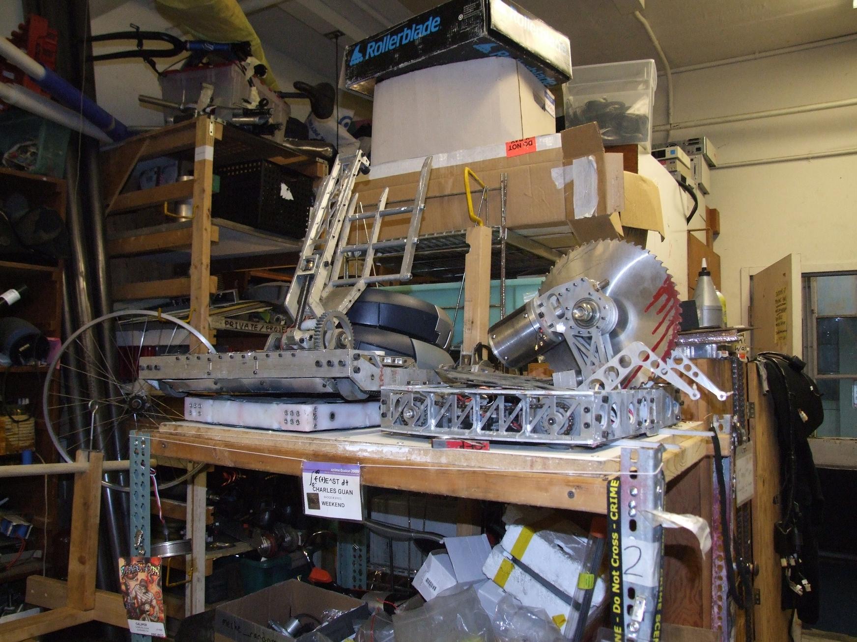
Yeah… about them robots
That doesn’t look too good. The bots have all been sitting, piled on top of my cart of miscellany, since February. They’re relatively undamaged as far as active combat robots go, but Moto took its toll on the drivetrains. I went through 4 and a half gearboxes at Moto, running through all of my spare 24:1 drill gears. After Arbor was eliminated from the competition, I harvested its gearbox parts to keep Überclocker running…but not for too much longer.
Long story short, Arbor has 1 semi-working drive side and Clocker has zero.
cold arbor
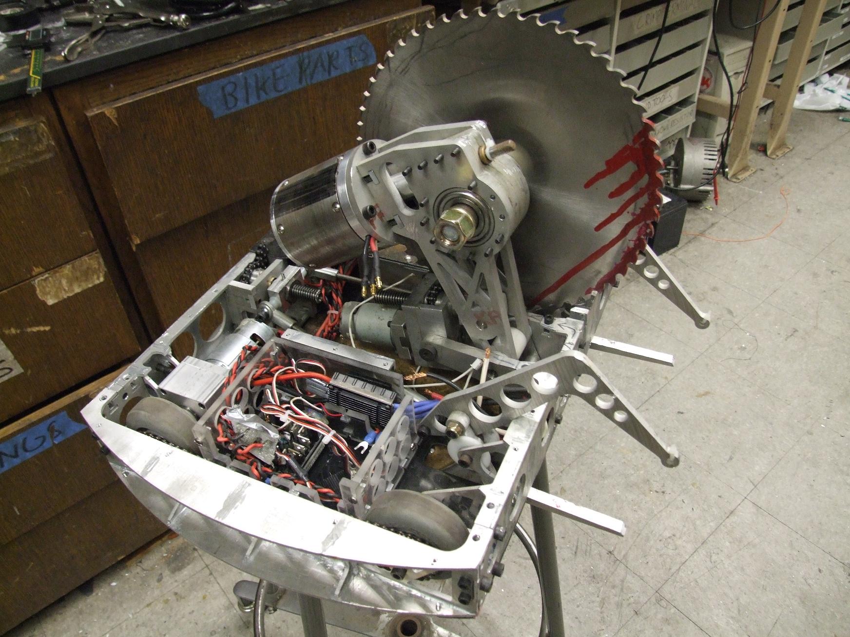
Here’s Arbor after retrieval from the cart skydeck. Past the drivetrain (or lack thereof), it’s also been the subject of parts harvesting. I think I’ve stolen the two Dimension controllers (which were briefly used to run Segfault), the Spektrum receiver, and the 5 volt BEC out of the electronics bay – those are all scattered about MITERS and so need to be retrieved or replaced.
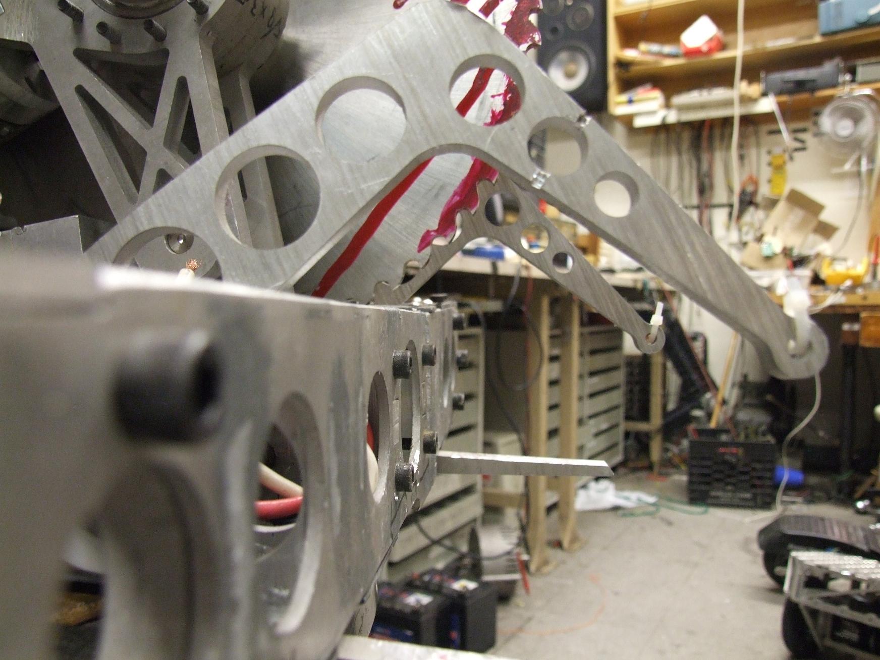
One of the issues I intend to address is the front frame assembly. First off, it’s physically bent about a degree and a half. Not much, but several of the braze joints in the bend region have failed and some of the sheet metal has become twisted. This was probably just a result of battle, but either way it’s unsatisfactory.
Much of this front assembly was designed using 5AM Joltgineering™, therefore structurally unsound. I want to do a better job making it stiffer, so the plates may be recut and rebrazed.
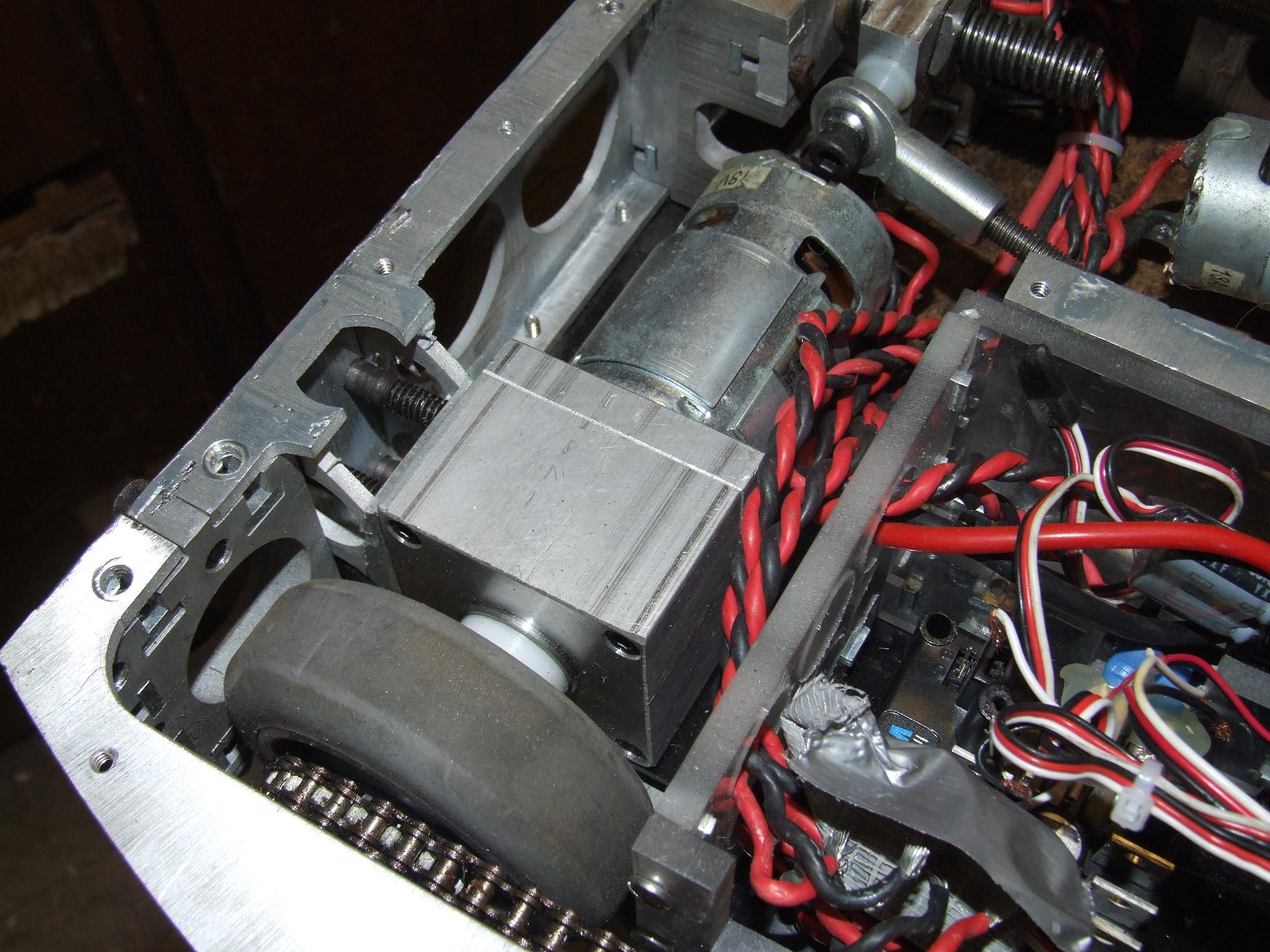
Gearbox issues aside, I’m otherwise satisfied with the drivetrain. The oversquare wheelbase and central mass location means that Arbor actually handles very well. The drive is fast, but the super-soft McMasterBots wheels were grippy enough to avoid uncontrollable sliding. I’m also satisfied with how the Delrin hubs have endured in the front half of the drive.
Comparatively, ‘clocker handles like a total brick since all of its mass is in the rear 33% of the robot.
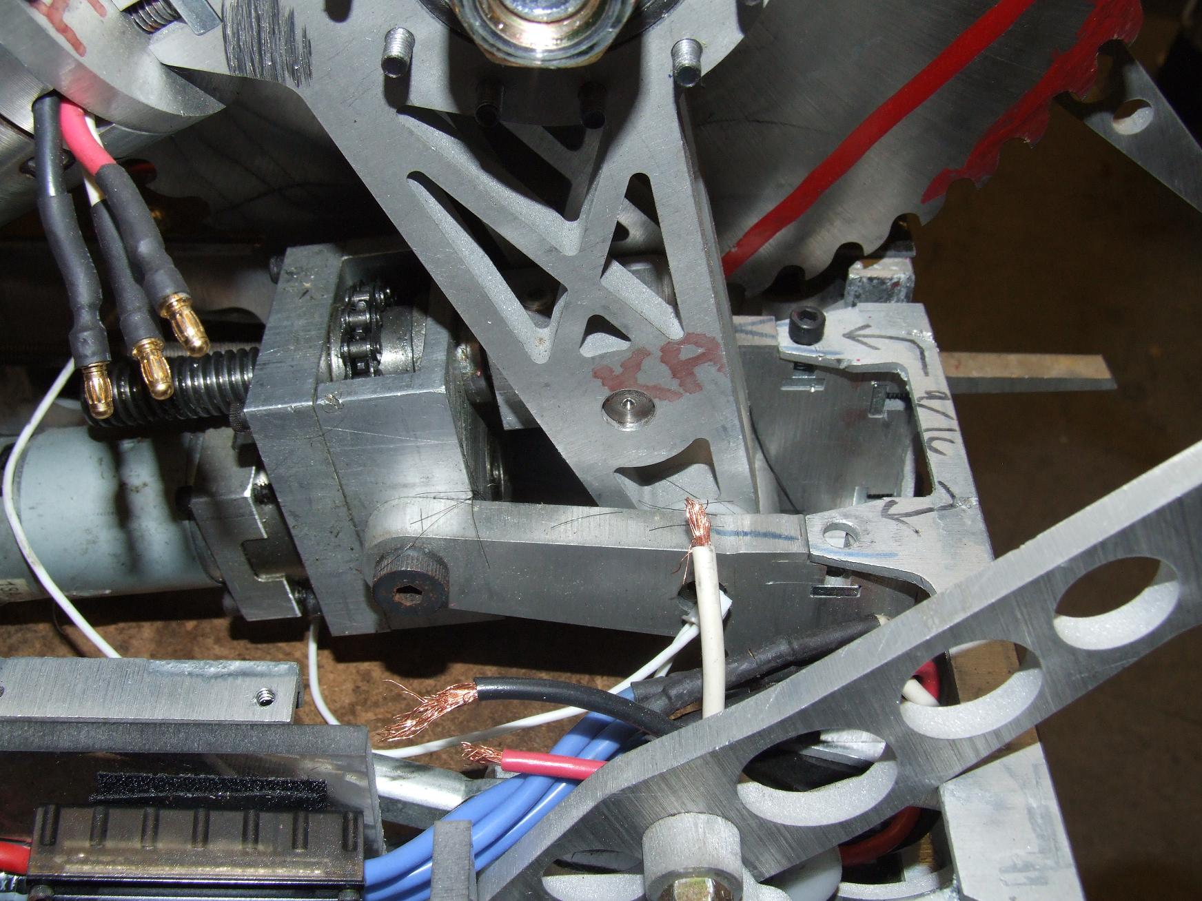
But I’m extremly dissatisfied with how the whole swinging saw assembly is mounted. If you call, several months ago in the last Arbor update before the Motorama update I never wrote, I said:
However, this was the first time that I discovered that Arbor would never work as I anticipated in its currrent configuration.
I was referring to this. In what must be yet another symptom of 5AM Joltgineering™, I somehow made the entire 14 pound swinging saw pivot off the front sheet metal assembly. As in, everything. All moment loads, all bending, and all shocks were transmitted through the beefy 3/8″ aluminum saw pivot mount…. right into the 1/8″ aluminum plate in the front. The above picture shows the “load triangle” pretty well. One point of the triangle is located at the left side by the actuator trunion screw, and the other two are effectively shared by the two cap screws from the right side (front) and the screws on the top and bottom, which… happen to be missing, and probably were all through Moto.
From a Course II standpoint, this assembly is one giant piece of unwanted flex. It became very clear during Moto (and during testing) that the entire saw was prone to pulling itself into the material (or opponent) and becoming stuck hard simply because the whole frame twisted several degrees due to the torque of the worm gear drive.

My plan for redressing this problem is to make the saw’s structural loop much larger. Effectively this means swapping actuator positions – placing the saw actuator at the back end of the robot and the claw actuator where the current saw actuator is.
The light red, green, and blue lines indicate where the current structural loop of the saw lies, and the dark shades show where it should lie after modifications. The bigger the loop, the more the structure can resist torque about the orthogonal axis (in this case, the direction of saw rotation). But because I’m keeping the green line a constant length, I should have the same “swing” of the saw available.
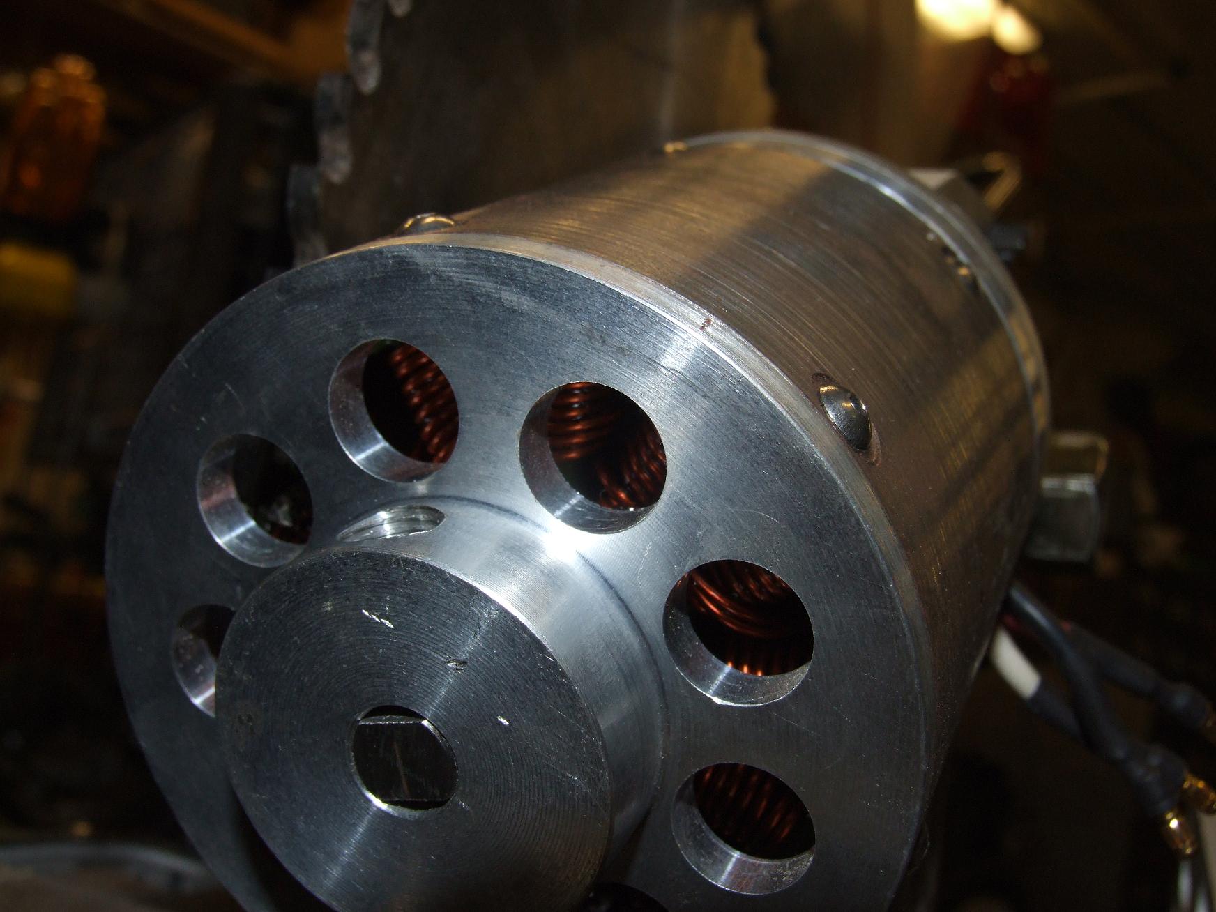
As long as I’m wailing on the saw assembly, I might as well talk about Deathrunner. It’s been shiny, menacing, powerful, and reliable, but Deathrunner is going to be replaced with something else for D*C.
But why? Well, Deathrunner weighs 4 and a half pounds, was wound somewhat hackishly (the number of turns and wire fill percentage is a total waste of the stator), and hangs awkwardly off the saw arm. Even worse, it’s sensorless. Now, I could very well add sensors, but then I run into the problem again of not having a sensored controller powerful enough to feed it – no amount of DEC modules will drive this thing. I noticed that the sensorless controller had problems keeping up with sudden changes in the motor speed, such as those caused by the saw biting something.
Overall, the weight could be better used by a short Magmotor (!) or something similar. It’s much easier for me to control a DC motor, and I don’t have to worry about its transient response.
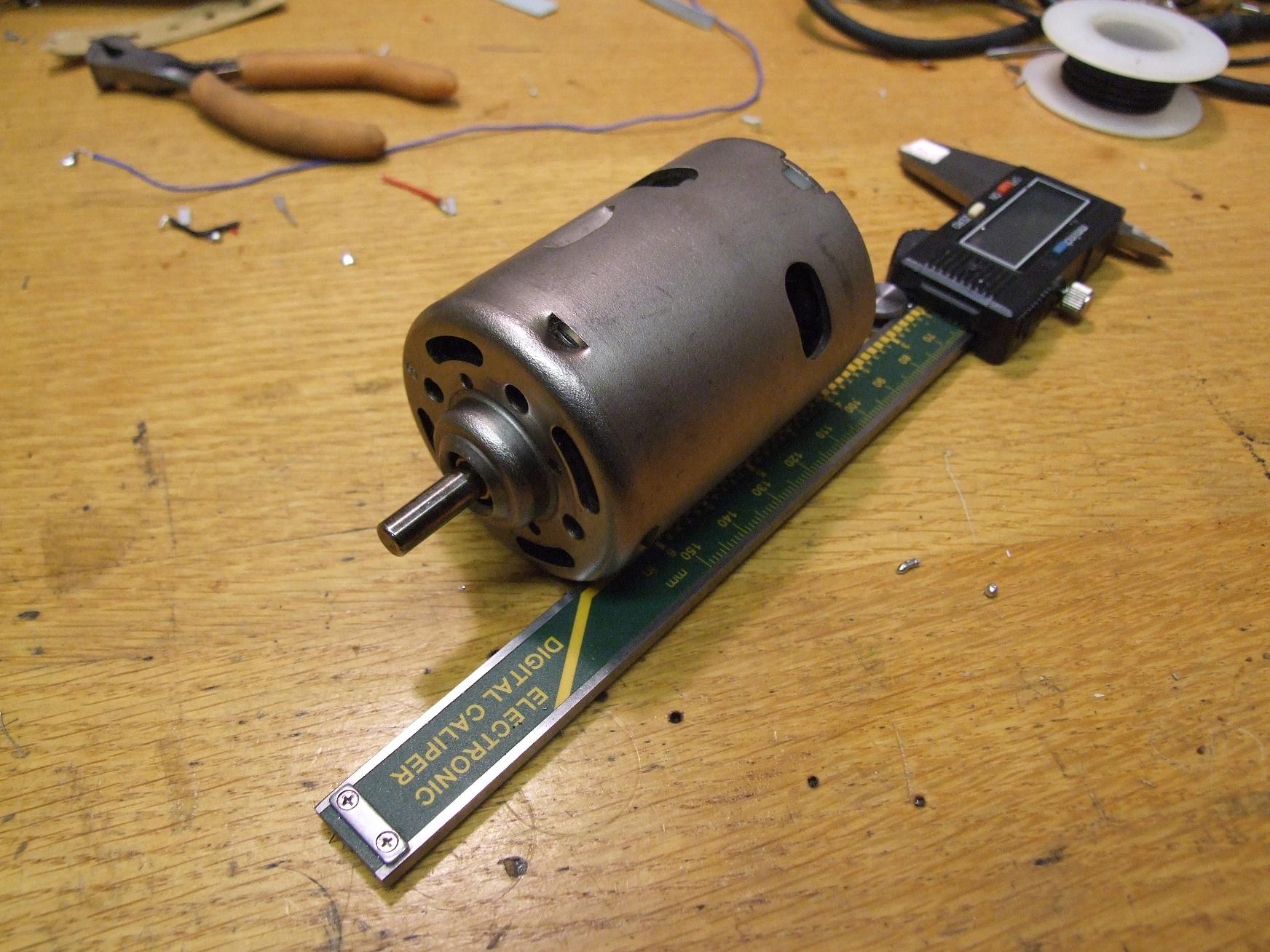
For now, the candidate motor is a big DC brush motor about the size of the classic Mini-EV. It otherwise seem to share all the MEV’s charactistics, such as being fast and obnoxious. Since it IS a fast motor, I might put one stage of “pre-gearing” on it by harvesting parts from one of several junked industrial planetary drives I have in the cruft pile.
überclocker remix
Poor Überclocker.
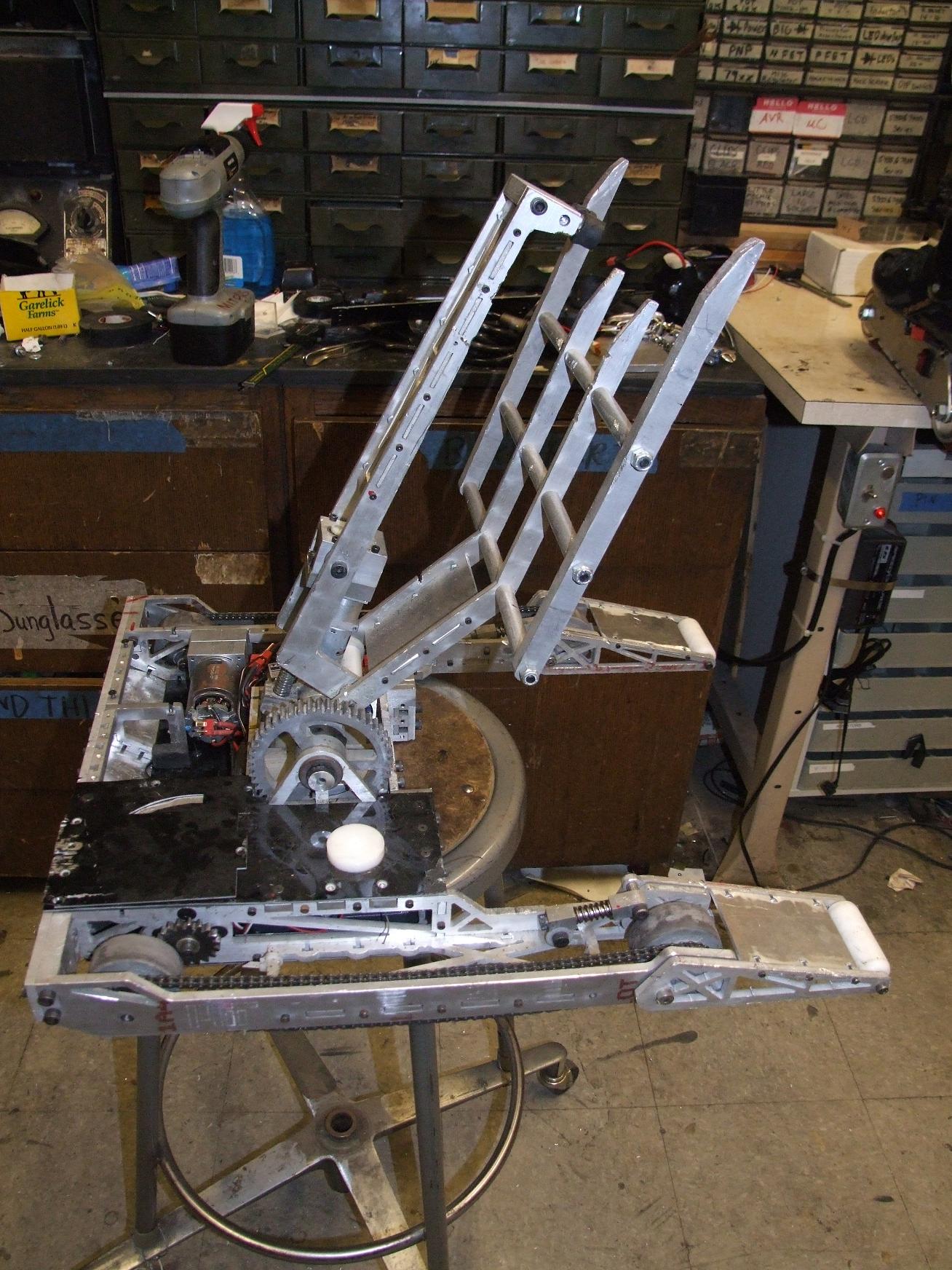
Being 1 event older than Arbor, it’s more beat up. A few things are bent, screws are missing, and there are little saw nicks all over the place from Freakin’ Enforcer, but fortuntely the major structural components are still sound.

Again, the number 1 issue is the drivetrain. More precisely, it’s the lack of one. A combination of “DeWalt motor into Harbor Freight drill gearbox” and battle impacts destroyed both gearboxes. At the event, I pulled parts from Arbor to keep them running, but ultimately Clocker lost out of the tournament by virtue of not being mobile enough to attack anything.
Besides the gearbox, the external portions of the drive have been flawless.
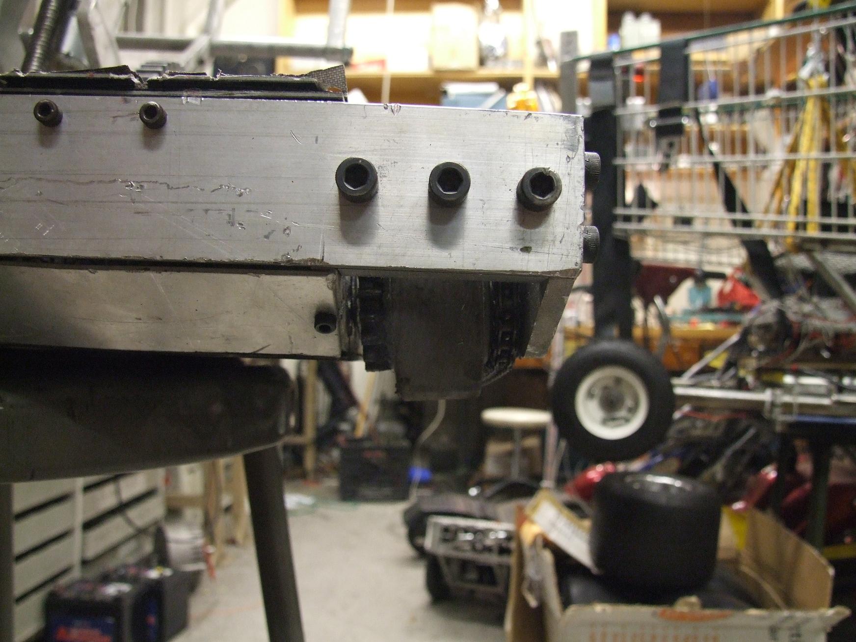
Well, most of it. This right side has apparently been gimpy since fight #2 at Moto because the internal binding screw backed out, so the standoff went all over the place. In the grand scheme of things, an easy fix.
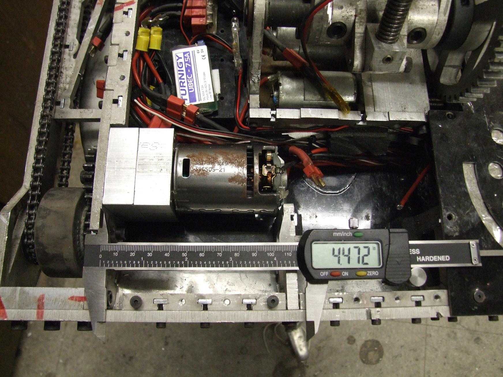
I have about this much space if I want to switch to a stock solution like the Magnum 775 motors (which actually seem to be a bit too long). If I want to keep the current drill gears arrangement, I’d have to return to 550 motors because I’m out of 15-tooth pinions for 24:1 drill gearboxen. That would be a pretty stiff power and thermal mass sacrifice that I don’t feel like making.
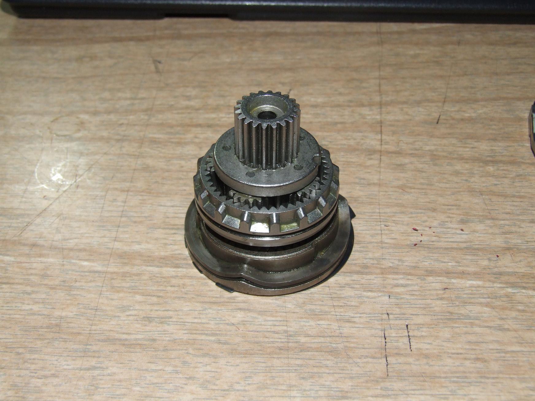
Or I could keep fucking around with drill parts. A while ago, I posted some information about the 3 speed DeWalt (read: legit) drill gearboxes to Delphi Robotland, including a gear ratio count and pictures of all the stages.
With some crafty adaptation of the 2nd stage gear carrier’s sun gear, I could use the first two stages as a 17:1 planetary gearbox that has bigger and meatier and more gears than the comparable import-class drill. I started thinking about it, and hopped into Inventor to model some of the major components.

Here’s a preliminary layout showing some of the changes to be made to the parts. The sun gear will be turned down to a 14mm stub shaft, which will ride in a 14x20x12mm needle roller bearing. Its center is bored out to 12mm.
The first stage ring gear with the weird wavy flange remains as the first stage ring, but I intend to machine off the weird wavy flange to save on diameter. The second stage ring gear (the one with the dog clutch teeth that are unmodeled above) will remain the same.
All the ring gears will be heat-shrink-fitted into a custom aluminum casing…

…which looks the same as the current Clockerbox, and is made from the same 2″ square aluminum.The difference is that now the motor mounting plate is actually a plate instead of, say, the entire back half of the gearbox. It makes things a bit easier to manufacture.
The output gear will be the same one on the robot now, and will ride on a short chunk of 12mm drill rod shoved into the bore of the former sun gear, and with a Double-D profile machined into one end to simulate the old Clockerbox output shaft.
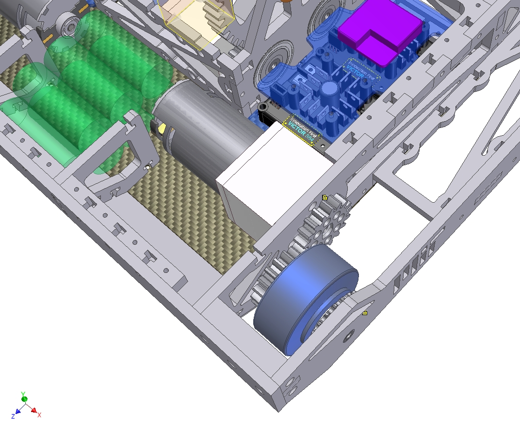
Dropped in place…
This new assembly is about 0.1″ longer than the current motors, which is an acceptable change.
I might switch Clocker over to the same kind of McMasterBots wheels that Arbor currently uses. It doesn’t hurt to have more traction on the D*C stage, especially since going from 24:1 to 17:1 is going to boost the robot’s top speed even more.
Here’s where I get to find out if my robot driving skills have faded any from the 2003 Test Bot 2.0 days.
While I have the gearboxes designed, I’m debating whether or not it’s worth just going with the 775 gearboxes because they are a stock solution – that is, I don’t have to build them. It’s mostly a matter of cost versus time spent – I could buy the 4 gearboxes (assuming Arbor also needs a pair) for $400 or so, or build two FrankenWalts for virtually free, and if necessary, two more for about $100.
It comes down to do I think I can get them done in under approximately 32 hours because my time is apparently worth about that much this summer.


