Chibi-Mikuvan: More Stickers is More Power, Right?

VAN SWITCH!

The semesterly action has died down to the extent that I no longer know what to do with myself. This is the gap of three-odd weeks between the end of the spring semester and the beginning of the summer action. As usual, the IDC is hosting mobs of Singaporean students as well as MIT students involved in The Collaboration. Like last year, I’m about to indoctrinate a fair percentage of their current freshman class with the Church of Chibikart. The specific implementations of this summer’s Silly Go-Kart Church Camp will be discussed soon. There are omniwheels.

During this break, I am of course going to be working my various problem children who need my attention. Most of this will involve facilities upgrades and improvements of the current robot or silly go-kart fleet.

  • Changing Überclocker over to easily-swappable Banebots wheels – I talked about this near the end of the Motorama event report. The 40A durometer “McMasterbots” wheels are very great for traction, but they wear out quickly and I have to individually machine each wheel to fit my hubs. Hypothetically, once switched to fast-swap hex hubs, I can replace an entire wheel set in 5 minutes flat.
  • Finishing Chibi-Mikuvan’s liquid cooling loop and creating the telemetry system / electronic dashboard.
  • Maybe even working on repairing the 1lb and 3lb bots (yes, including Colsonbot) for the Bot Blast event this coming July!
  • Maybe maybe some more real-van bodywork.

Truth be told, I’ve actually been spending most of the past week, and likely much of the coming weeks, designing something which I think is gonna be pretty damn interesting. This is a far out enough concept that I want to flesh it out concretely before taking it public, so you’ll have to deal with this artificial cliffhanger for a bit longer.

In between, Chibi-Mikuvan has been accruing more stickers. It is a well known principle in auto racing that stickers make you faster!

Well, perhaps a different type of sticker. They most likely didn’t mean….

Miku stickers!

It’s amazing the huge range of quality you are presented with when you search for “miku sticker”. I gradually homed in on one sticker/decal house with an eBay store, based in Malaysia, that had the highest count and variety of Miku stickers. The characteristic I was seeking the most, though, was huge. Loads of stores had the tiny notebook sticker or cell phone decal, but only this place had them in 33″ tall, and in high quality with the transfer layer.

Granted, the shell isn’t that tall, so some parts of Miku will necessarily be lost. I decided this was fine, though, as most itasha decor seems to focus on making the most recognizable parts of the character as large as possible (I need LED rims). I think for this version I’ll spare the fully custom paint job – it’ll be stickers on white to start with.

What followed was days of arduous experimental Miku-placement, researching and answering the toughest of unresolved issues in this field such as “Is it tacky to have more than one Miku per side?” (The above example would indicate no, it isn’t).

Dry erase marker and masking tape was the layout method of choice. I scribbled roughly where body lines were going to go in order to come upon a satisfactory placement.

This one, at least, was fairly obvious. It was of the exact correct height and aspect ratio to take a ride in the rear window impression.

And on the left side.

I was conflicted on whether to use only the two largest ones, or also include the others. The two in question are of the same art style and by the same artist (KEI), giving a more cohesive look, but of course had poor coverage. The two art styles shown here definitely clash a little.

After placement was finalized, I rough-trimmed the stickers to shape, applied them, then very carefully precision-trimmed the bottoms with a craft knife. In all, the results were quite good.

I actually ordered another pack of stickers – this time, with more logos and banners (the single lone Hatsune Miku logo wasn’t enough!). They should arrive soon.

The right side, for now, will lay a little more bare. Maybe all the new ones will go on this side!

I moved onto the issue of car number. The two numbers traditionally associated with Miku – “01” and “39”, are both taken already! Sadness. Well, I’m certainly not going to try and claim the 01 number from the team until I beat them.

So at least for now, let’s roll with “3939”.

The door decals were printed on sticker vinyl by my good buddy Ted, who knows graphic things and stuff and whatever. I tried printing them, but my poor CMYK only printer can’t handle the BRIGHT NEON MAN-GENTA coloration of Miku’s graphic logo (the 初音ミク bit) – it kept coming out orange-red. Apparently, professional printers just have a BRIGHT NEON MAN-GENTA color channel. The lettering itself was made using Inkscape.

I carefully knifed the number out by hand (and ruler) – no cut templates were made. I supposed I could have fed this into the vinyl cutter if I had planned this better. In ambient room lighting, it looks tacky because the background stands out, but in bright outdoor light, it’s not as noticeable.

replacing the Trackstar

Little known fact: For one reason or another, after the previous garaging video, the Trackstar 200A controller died. It didn’t die in flames – rather, one phase simply stopped driving. So in fact I could ‘skateboard’ Chibi-Mikuvan up to 5-6mph, hop in, and it would actually still keep on driving. However, with a dead phase, it couldn’t start or run at low speeds. Inertia! It works!

Having one of the student teams this past spring suffer a Trackstar failure in almost exactly the same fashion, I began to suspect that the up and down jostling and high frequency impacts of being used in a vehicle was causing the signal board to come loose inside. As documented in One Thousand and One Hobbyking Amps, the signal board on these things is held on by 1 small header, and allegedly retained by rubber foam tape. However, when I pulled that unit apart, the board came off really easily, with not much compression of the foam tape visible.

It’s my hunch that impacts shake the signal board header loose just enough to cause one bank of FETs to possibly become disconnected from the driver chips, and since the power board doesn’t appear to have any gate protection hardware (pulldown resistors and Zener diodes), that phase probably died instantly from cross-conduction or dV/dt damage to the gates.

I decided that the power board was not worth saving for a few reasons. First, it’s a massively heavy (6 ounce or heavier) board with copper conductor bars soldered to it – rework would have been borderline impossible. Second, it’s potted for waterproofing, as far as I can tell. The FETs are sandwiched right next to the conductor bars.

Hence, I gave in and just ordered a replacement. Damn you, Hobbyking!

This time, the first thing I did was to crack it open. Shown on the right is the number of tools I needed to use to do this. I have no clue what the hell these screws are supposed to be, but some prefer a 2mm hex, some a T9 (!?) Torx, and two of them Phillips.

Next, I took out my favorite contact cement & robot wheel retread compound & waterproofing coating & what have you. E6000, and its related adhesive Goop, are some of my favorite adhesives. In this case, I’m using it far more as a structural filler. I put 3 big globs of it on the near two corners and far edge of the board.

I’m basically resigning this controller to be never repaired, but that’s fine.

After replacing the controller, I joined in another MITERS silly vehicle proving session in the garage. This time, I couldn’t get the dashcam to stick to the helmet any more, so had to rely exclusively on random people filming, which always ends so well. The art and science of holding a camera steady is one that is only developed through a habit of documentation – most people can’t do it. This is all the useful video I was able to get that wasn’t jittery, out of focus, or cut too short.

That sound at 0:16 which is oddly reminiscent of a gear falling out of a gearbox is…. yeah. Under heavy motor braking, once again the pinion got yanked off its taper by the action of the helical bevel gear. It proceeded to screw itself back in once I hit the throttle really hard. I need to remake that entire input shaft at this point, since it’s doubtlessly been gouged up and damaged by the slipping gear. I’m also going to reduce the maximum motor braking force back down to 25% – I left it at 50% for this test – for actual racing, since it seems to be a point of reliability trouble.

This run, I beat my previous time (57 seconds) by 2 seconds since I carried more speed through the end turns. I’ve figured out how to get this thing to not understeer near top speed – the answer is lean all the way forward. I believe this puts me within 2 seconds of the all-time garage record by Tinykart.

Left to do on Chibi-Mikuvan is making the water cooling circuit, for which I have all the parts for already. The next thing to do after that is to make spare everythings: battery packs and entire motor-gearbox assemblies are first. This way, if I have a motor or gearbox failure in battle during the race, it’s easy to swap and get going again. Eventually, I want to set up the 2.00gokart course again and run one full simulated race scenario – as many laps as possible on one battery, a battery change, and a tire change.

I’ve signed up for the Detroit Maker Faire race, which is a feasible one to get to, so shit will get real soon!
Miscellaneous Van Adventures: Fuel and Coolant

Ongoing van facility improvements have been happening as the semester has been winding down, now that the 2.00gokart season is over.  Strictly speaking, I’m well past the point of needing to do something, but all of those boxes I’ve been getting from Rock Auto over the past few months are starting to be overbearing. I think I have a full roster of parts to replace or fix anything that could potentially wear out or break next – things like a new water pump (like I’m ever going back into that engine), a transmission rebuild kit (it was on sale, OK?!), enough oil filters for the next 100,000 miles, and so on.

I’m doing unnecessary part repairs for two main reasons – first, so that I explore more of the subsystems that might not have been touched since the Bush Administration (no, I mean the first one in 1988), and second because I’m putting off more bodywork. On that front, I’m glad to say that all of my back-alley work has survived the winter.

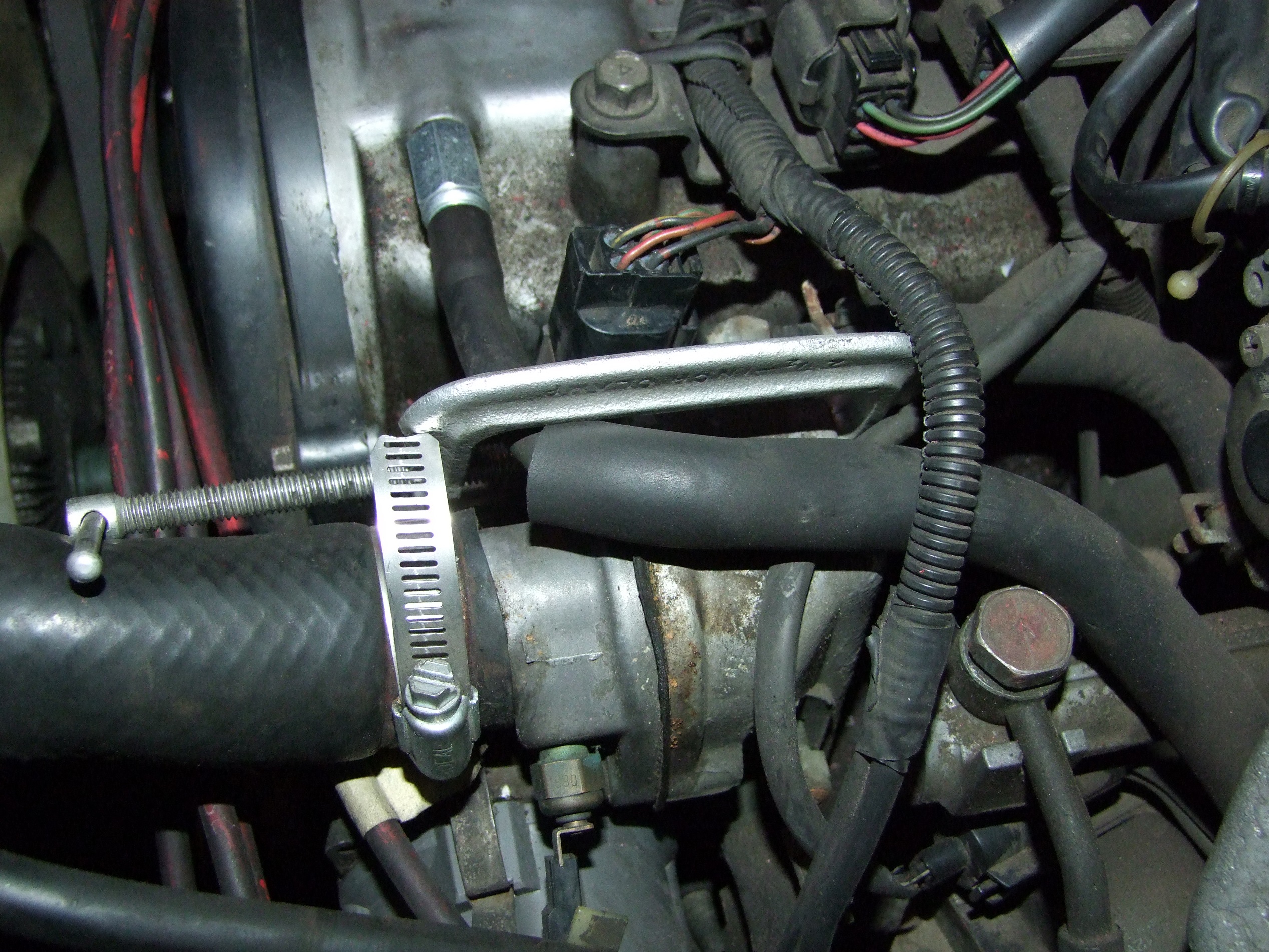
One of the things that I was going to do immediately last year, but of course dropped because Well It’s Working, is the C-Clamp of Thermostat Flange Retaining:

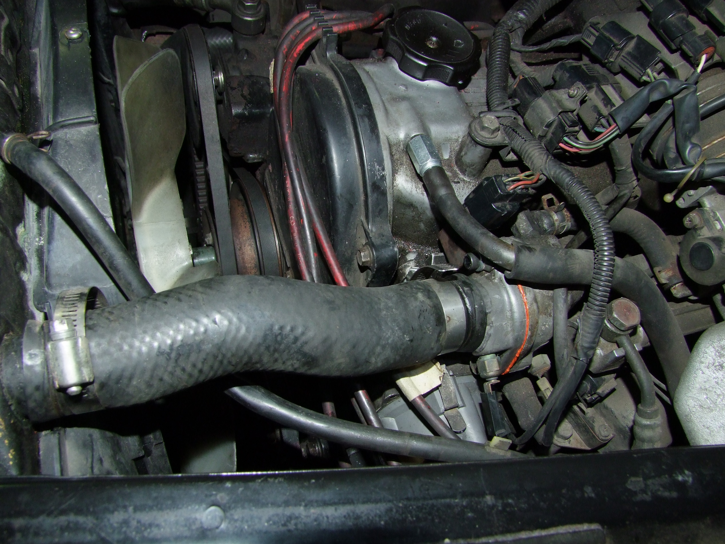
I noticed this flange had a broken bolt as soon as we dug into the engine bay in the very first van adventure of OPERATION: BAD TIMING. It was the cause of a minor coolant leak. The seller did mention it went through coolant and he just topped off the radiator as needed, so this was probably the root cause. I threw a 2.5″ C-clamp on it just to hold the gasket together and mostly resolved the problem for the next year.

Over many cool-hot cycles, the C-clamp began to creep and every once in a while I’d have to tighten it some more, or there would be small dribbles of coolant the next time I had to bust out Vanpower for backup. As summer approached, I figured I would need the cooling system functioning properly again. I caught a break during winter, where it had enough trouble keeping warm – keeping the heaters on would drop the thermostat needle to near cold after a few minutes in short trip operation.

It was time for the C-clamp to be returned to MITERS.

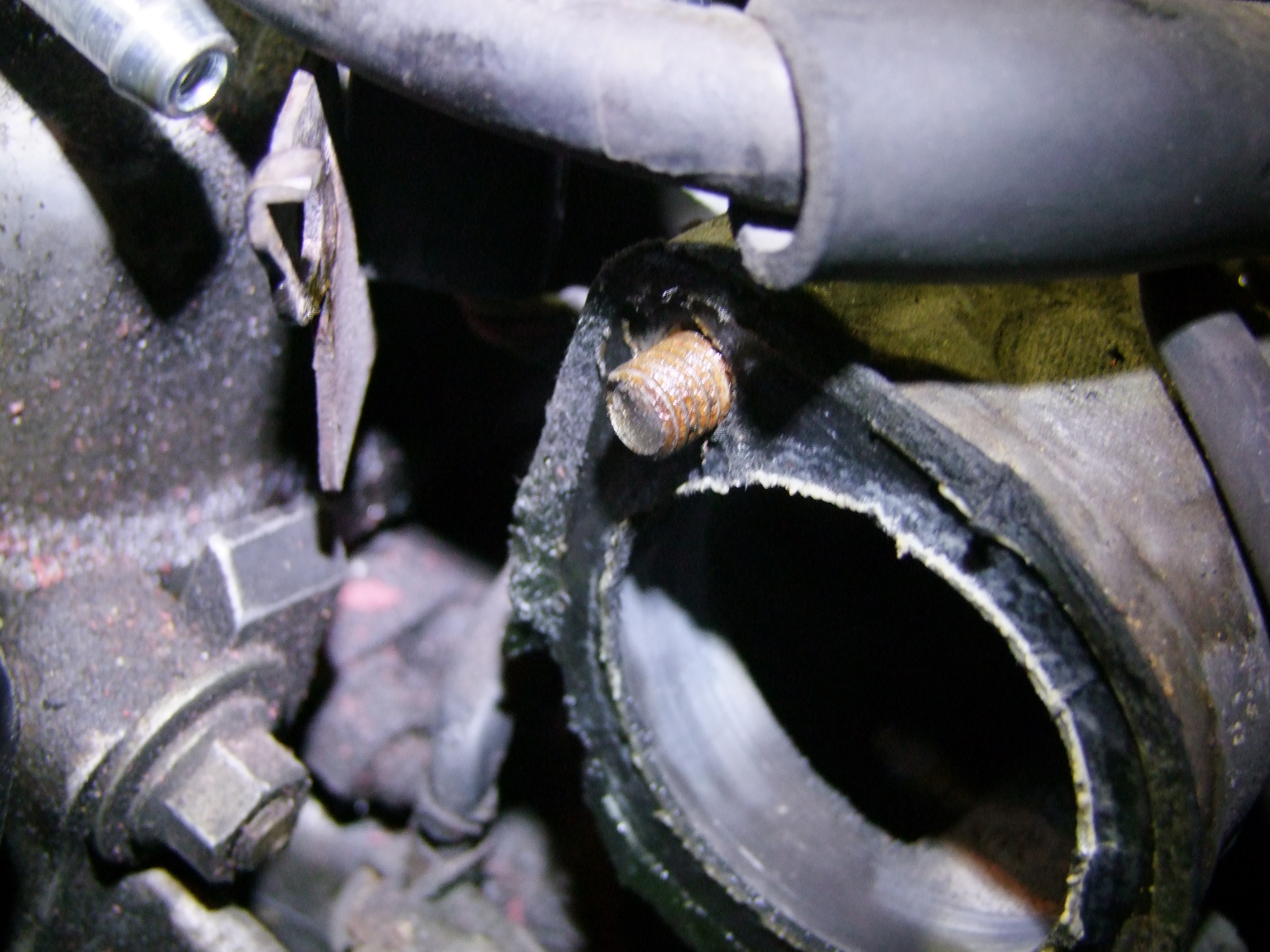
Step 1: Remove the upper radiator hose and thermostat flange to reveal the seized and broken bolt. Remove gasket in about 100 small pieces, because that’s how servicing this thing just happens: assume every gasket has already disintegrated by the time you lay eyes upon it.

Step 2: Apply heat guns, vise grips, and cheater bars for half an hour and shear the remaining stud off. This thing is in there hardcore.

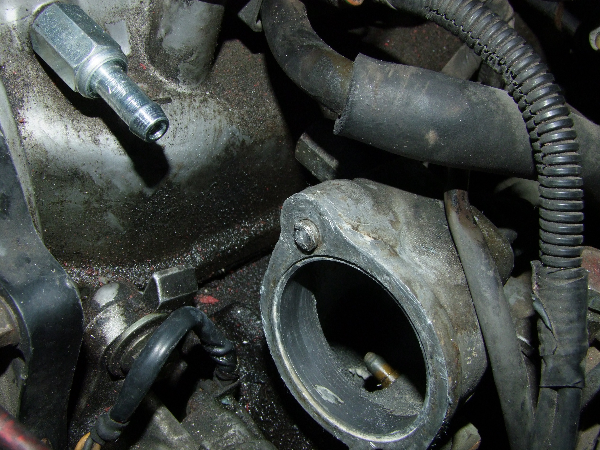
Step 3: Decide to drill and tap a smaller bolt down the center of the larger one, instead of trying to drill this one totally out.

Step 4: Discover that your drill plus bits are too long to fit in the gap between the engine block’s flange and the radiator.

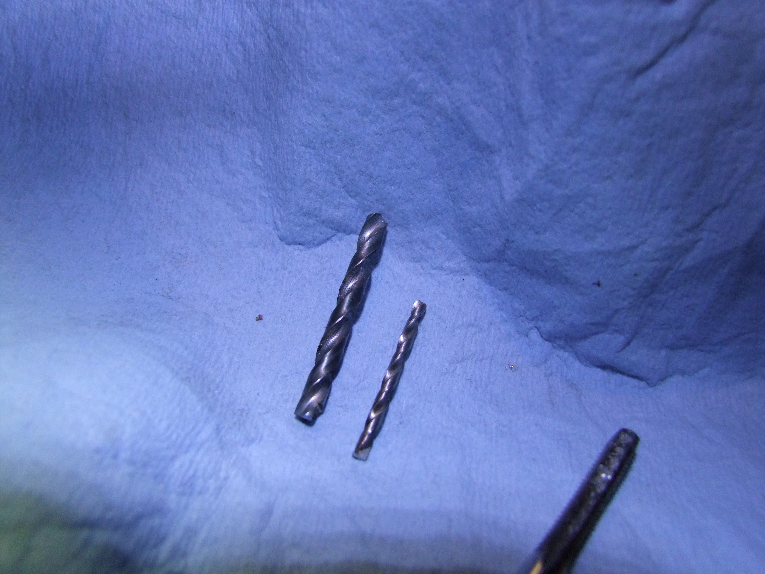
Step 5: Purposefully break two drill bits to make them short enough to fit. I executed two of my shop’s precious tap drill sizes to make this happen. I’m ready to be tried for war crimes.

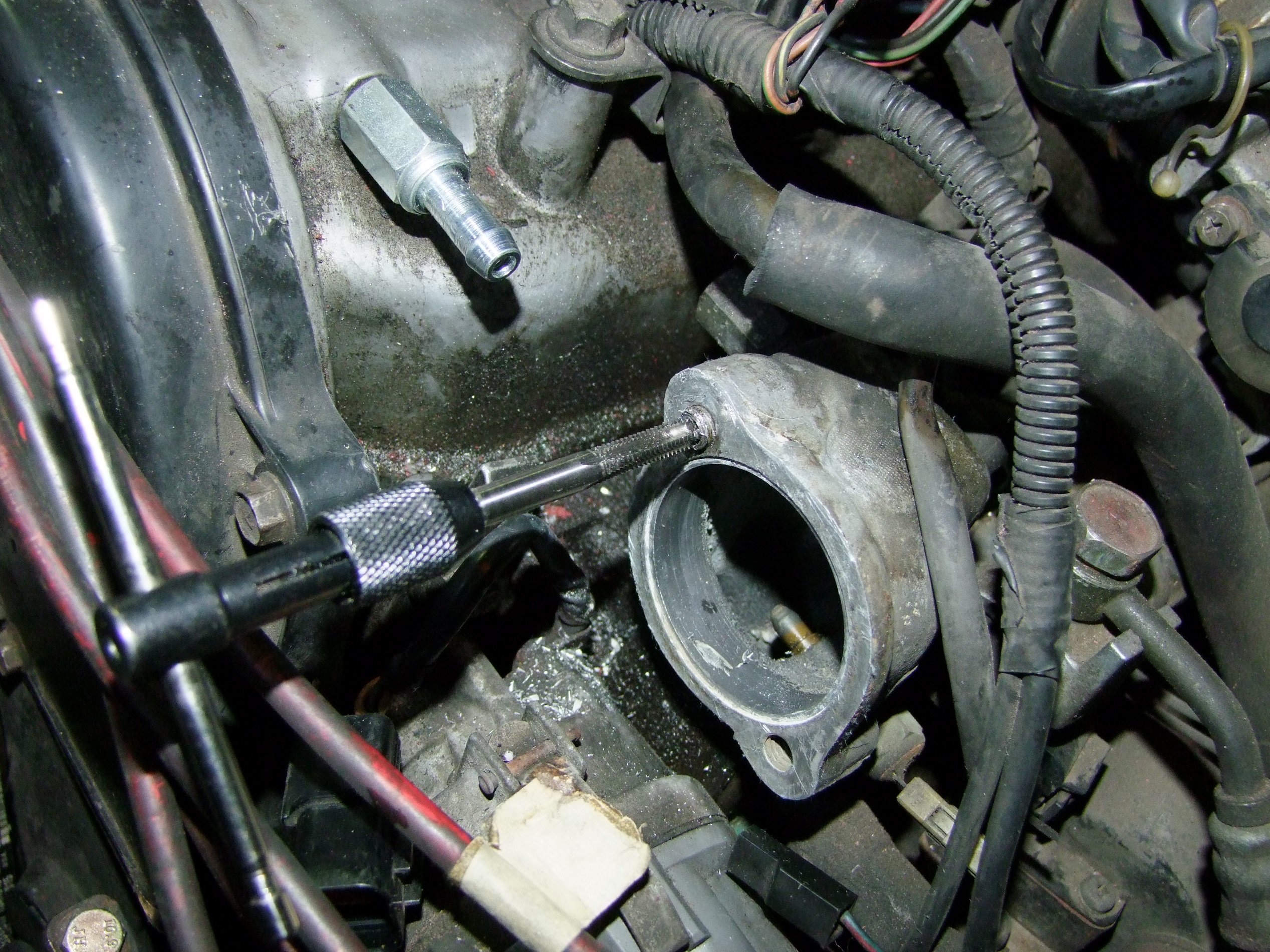
But it got the job done. I punched a center mark as accurately as I could, then used the small drill bit to pilot and the large drill bit to break through the bolt. Luckily, the small tap wrench fit in the available space just fine. I threaded this hole in M6 x 1.0. The original bolt was a M8.

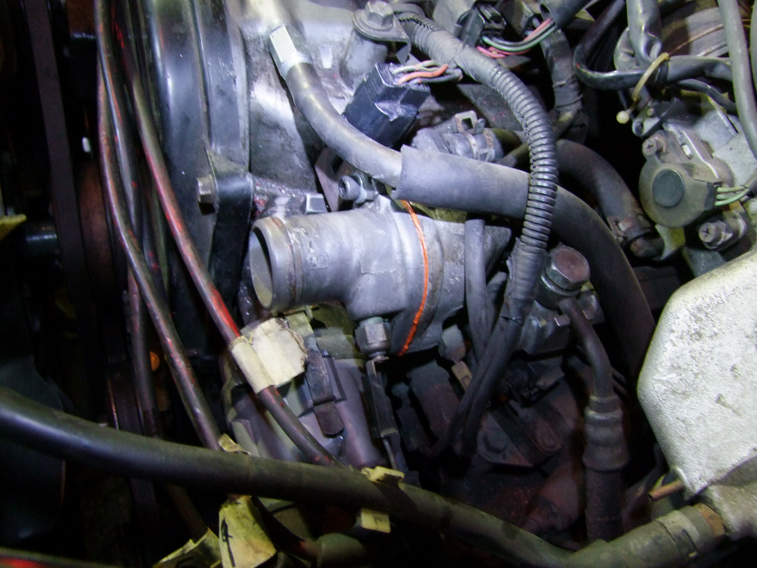
Finally, add high-temperature gasketing silicone compound and let it all soak for an hour or two, then tighten down the bolts a little more.

Pitching the system back together! I have yet to find a new droplet spot, so I assume it’s at least asymptotically solved.

Next up, Charles plays with gasoline!

The fuel system is one of the last things I have not looked into, besides the transmission (which I will accept is run by elves and unicorns). I know the condition of the upper half – injectors, filter, and the like, but not the fuel pump. I bought a fuel pump on Rock Auto months ago because I knew it was a part that could potentially wear out, and because it was on sale for $19.99. I figured if nothing else, I would use it as Chibi-Mikuvan’s motor coolant pump.

As Maker Faire Bay Area approached, I was entertaining the idea of driving cross-country to meet up with the west coast crew. Well, wouldn’t it be embarrassing  if the fuel pump quit halfway for some reason? At this point, I wasn’t sure of the exact operating mechanics of an automotive fuel pump, just that mine might be as old as I am.

To replace the fuel pump is a procedure which involves dropping the fuel tank from the underbody regions. Reading the service procedure for this was where I first learned that modern fuel pumps reside inside the fuel tank itself. Hmm, for some reason I always thought it slurped the fuel out through a straw or something. This is, again, where I point out that automotive engineering is an entire other world, knowlege-wise, from “mechanical engineering” defined broadly. It’s something which if you don’t pay attention to, you’d never know.

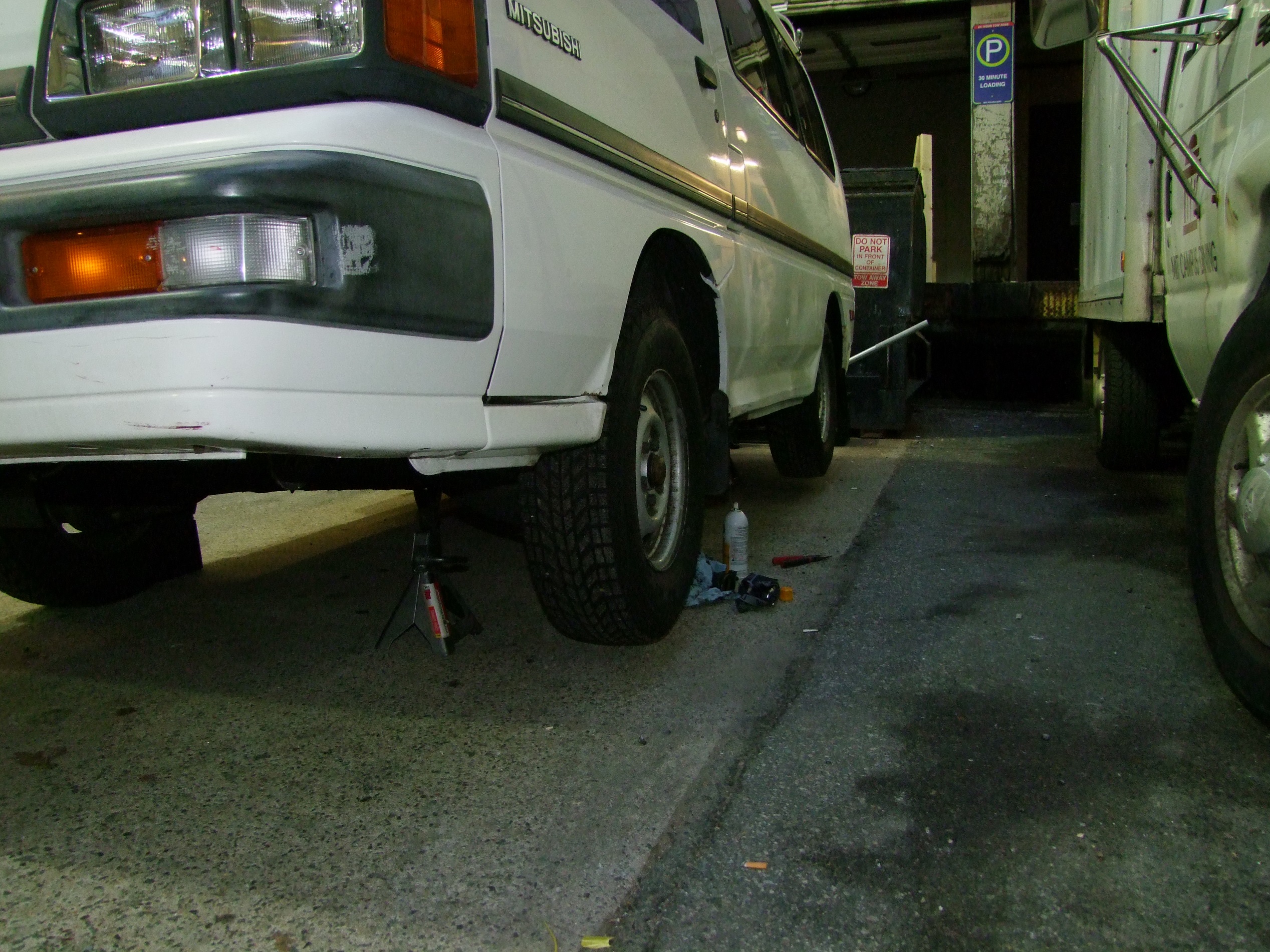
So up on stands we go! Prior to this was when I filmed vansaroundboston: a purposeful 30+ mile drive (that video was 1/3rd of it) to empty the tank to the last gallon. I unloaded this through the fuel tank’s drain plug.

First up in the service procedures was to remove the easy stuff. High pressure hose, return hose, and filler hose. This was where I figured the pump might have been worn out or on its last legs in some way – the service procedure called for disconnecting the power supply and then running the engine until it stalled from loss of fuel pressure. Well, I couldn’t even get it to start. My reading told me that there’s check valves and the like in the pump itself, so if those parts were leaking or failed, the pump would lose pressure instantaneously upon shutdown. So maybe this was a worthwhile gasoline-derived brain melting adventure.


The high pressure and return hoses coming off. There were a few other hoses and tubes to remove:

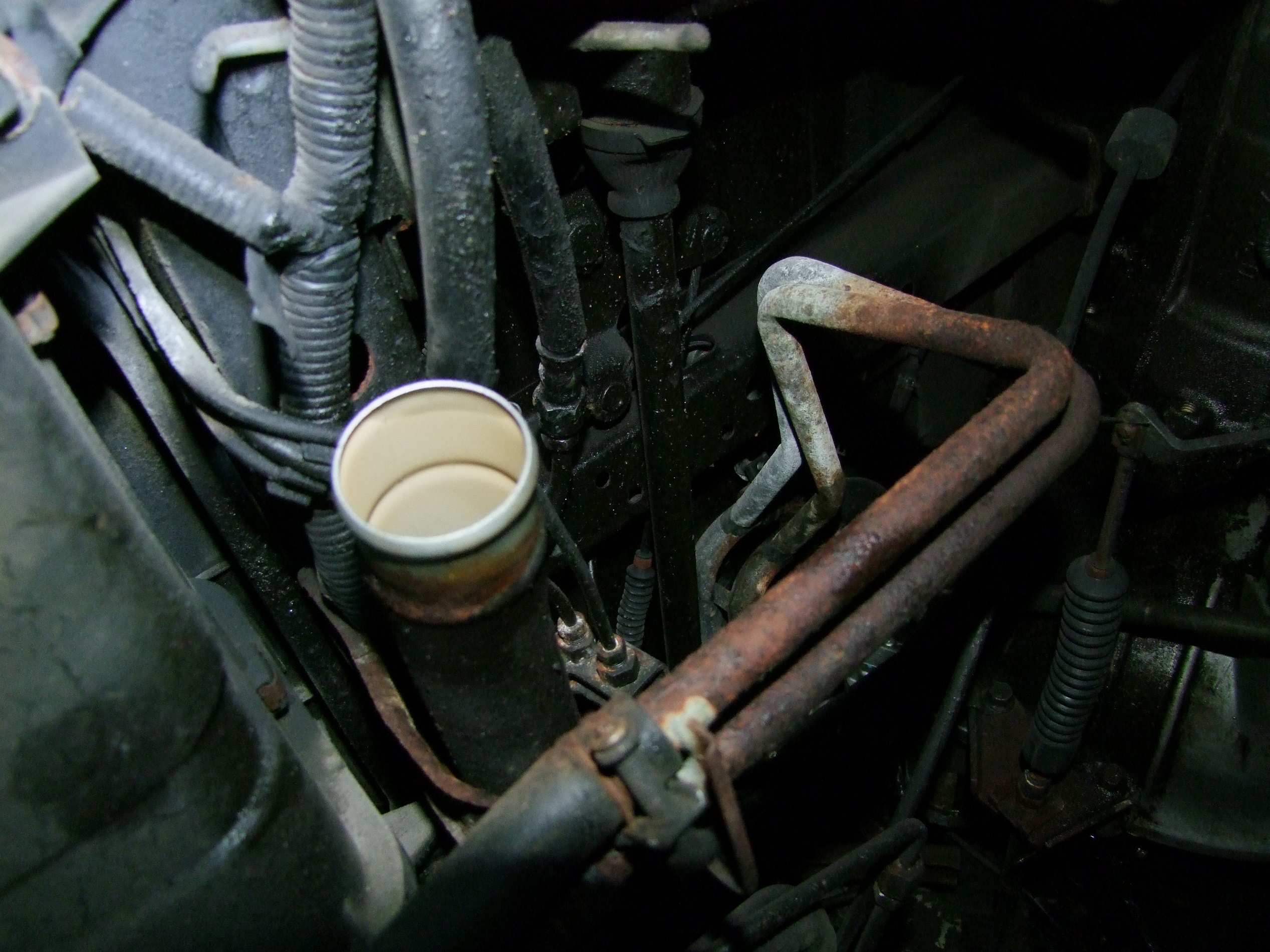
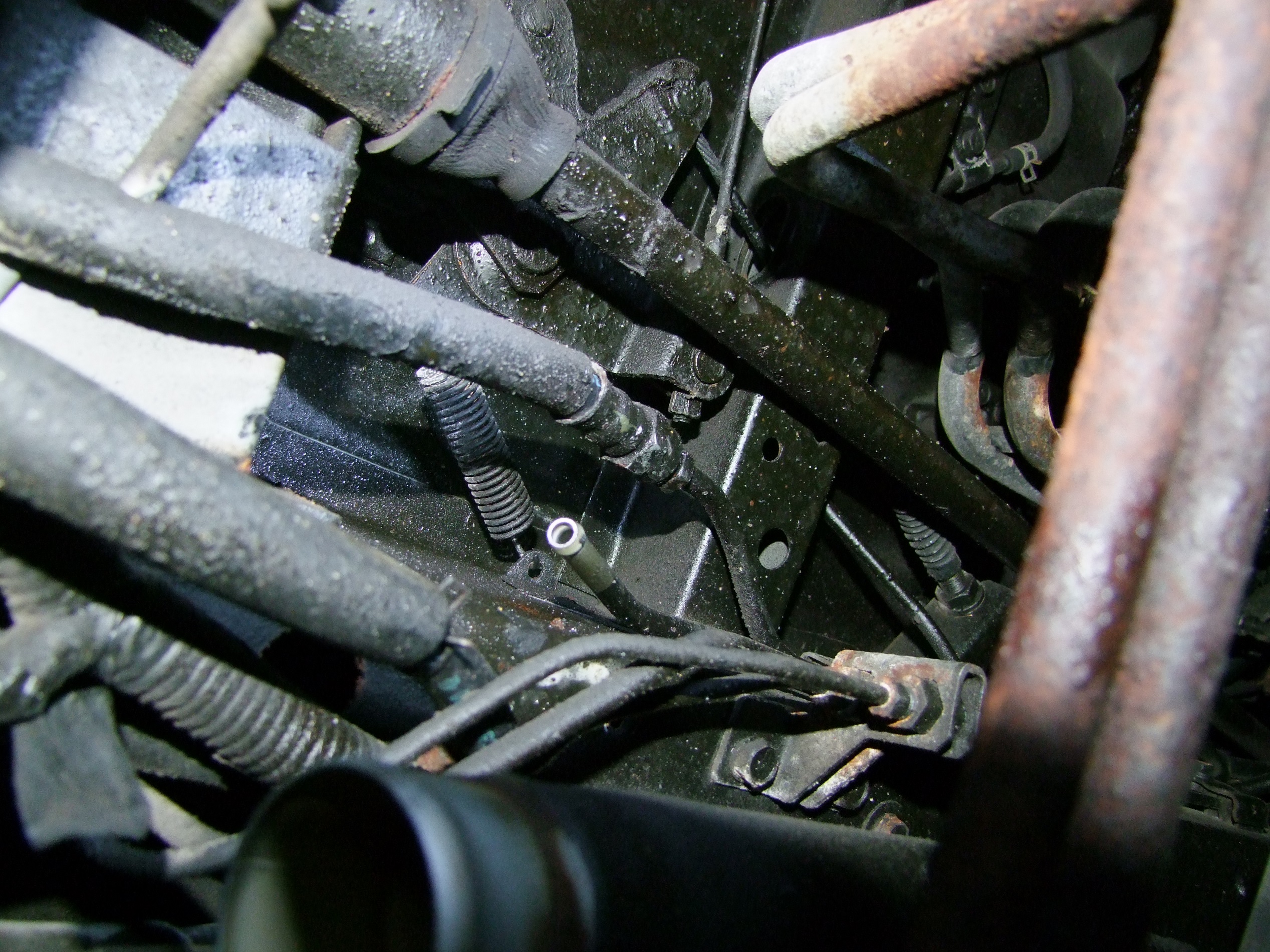
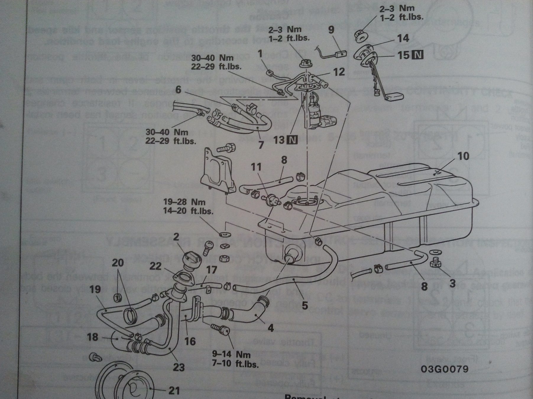
These disassembly drawings always show the part or subsystem in isolation, ignoring the fact that it was all buried in between 90 other parts, a frame rail, and the source of my oil leak. For instance, after the filler hose, high pressure hose, and return hose, I had to remove the vapor hose and fuel pump connector.

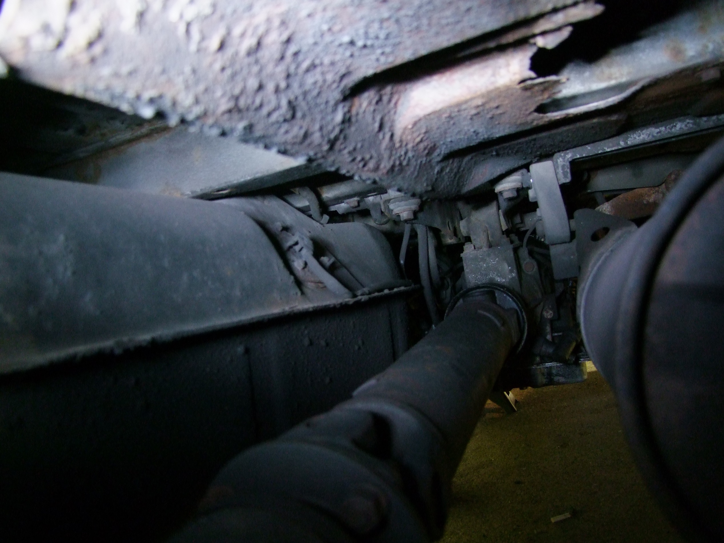
which is above the driveshaft and on the back side of the tank, you fuckers. Then, the vapor hose was literally impossible to get to in the stated order. If I, he who doesn’t look out of place in cosplay as Hatsune Miku herself, could not get his hand above the fuel tank with a hose clip plier to reach it, then how was anyone else going to?

I left these two connections to be removed after I unbolted the tank itself, which was also a Three Stooges-like experience, except there was one stooge only. When I untightened the four bolts retaining the tank, it didn’t budge. I banged on it from the side a bit to see if maybe there was another hidden bolt, and the whole thing falls onto my face.

Granted, it fell less than an inch, but it did weigh 15 pounds or so empty. I got a great black smear on my nose for this one.

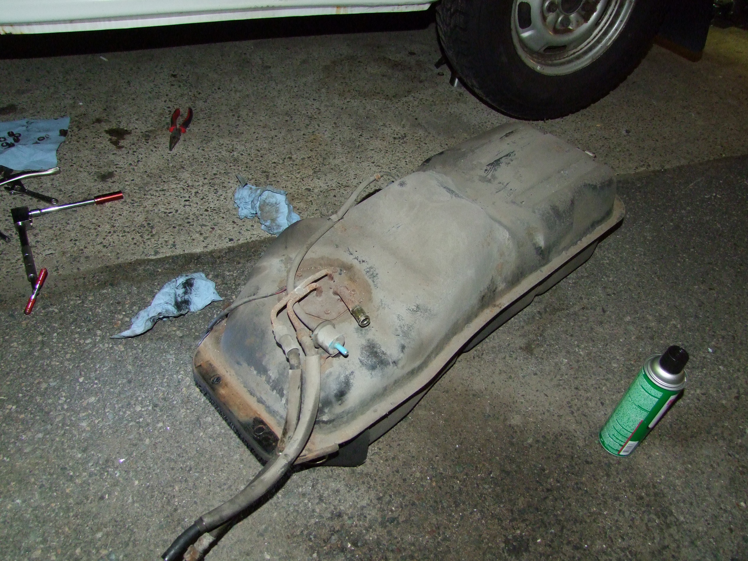
After a half hour of avoiding the oil leak sludge Self-Applying Undercoat while underneath, here’s the tank! It sure looks like this hasn’t been touched in a little while.

Observe the green can of CRC brake cleaner. I actually like using non-chlorinated brake cleaner for everything, because it seems to be just high pressure acetone in a can. Mild, but effective in combination with the spray jet. I use it to clean the shop bandsaws, or, in this case, to chase grime off the fuel pump flange.

Real brake cleaner is made of tetracreepywhatever, is much more effective, and dissolves like everything. I have a few cans of this that I only break out if lesser solvents can’t do the job. Like leaded solder, I figure this substance is going the way of the dinosaurs for being not part of this complete breakfast, so I’ll enjoy its disconcerting odor while it’s not banned in Massachusetts, unlike in California.

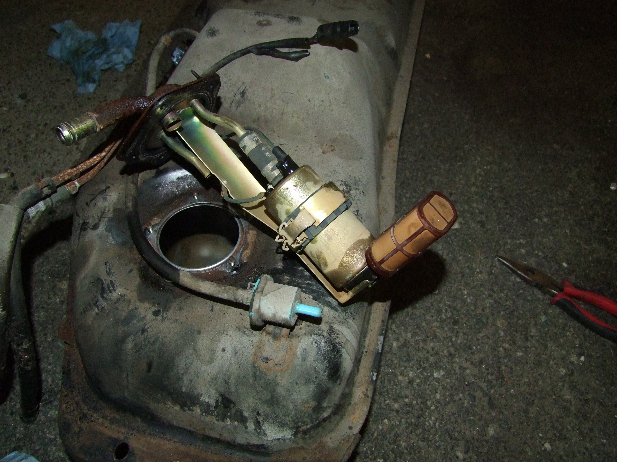
Undoing the 5 bolts holding the flange on, I reveal the fuel pump unit. It has its own little pre-filter attached that seems well-coated in goo.

Here it is side-by-side with my new pump unit. The old one isn’t in bad shape. Though it’s been in an environment that’s been majority-occupied by hydrocarbon vapors, which tend to preserve steel, and it’s still this tarnished, so who knows how old it actually is? I couldn’t find a date code, but did find a Nippon Denso logo. Unless the last service for the fuel system used OEM parts, this might be original equipment.

Strapping the new one in now.

Reinstallation was straightforward. I called for backup for someone to hold the tank while I started threading on the bolts, which was a nasty surprise for him because I didn’t say anything about the layer of oil sludge coating the underside of the fuel tank. I’m sorry, Julian. It was, indeed, quite gooey.

After I had the old fuel pump out, I was quite curious as to what went into one. The Internet™ had told me it was a DC motor running an impeller-type (centrifugal) pump. What the hell? Why would you put a brushed DC motor with its sparking commutator and all into a gasoline tank?

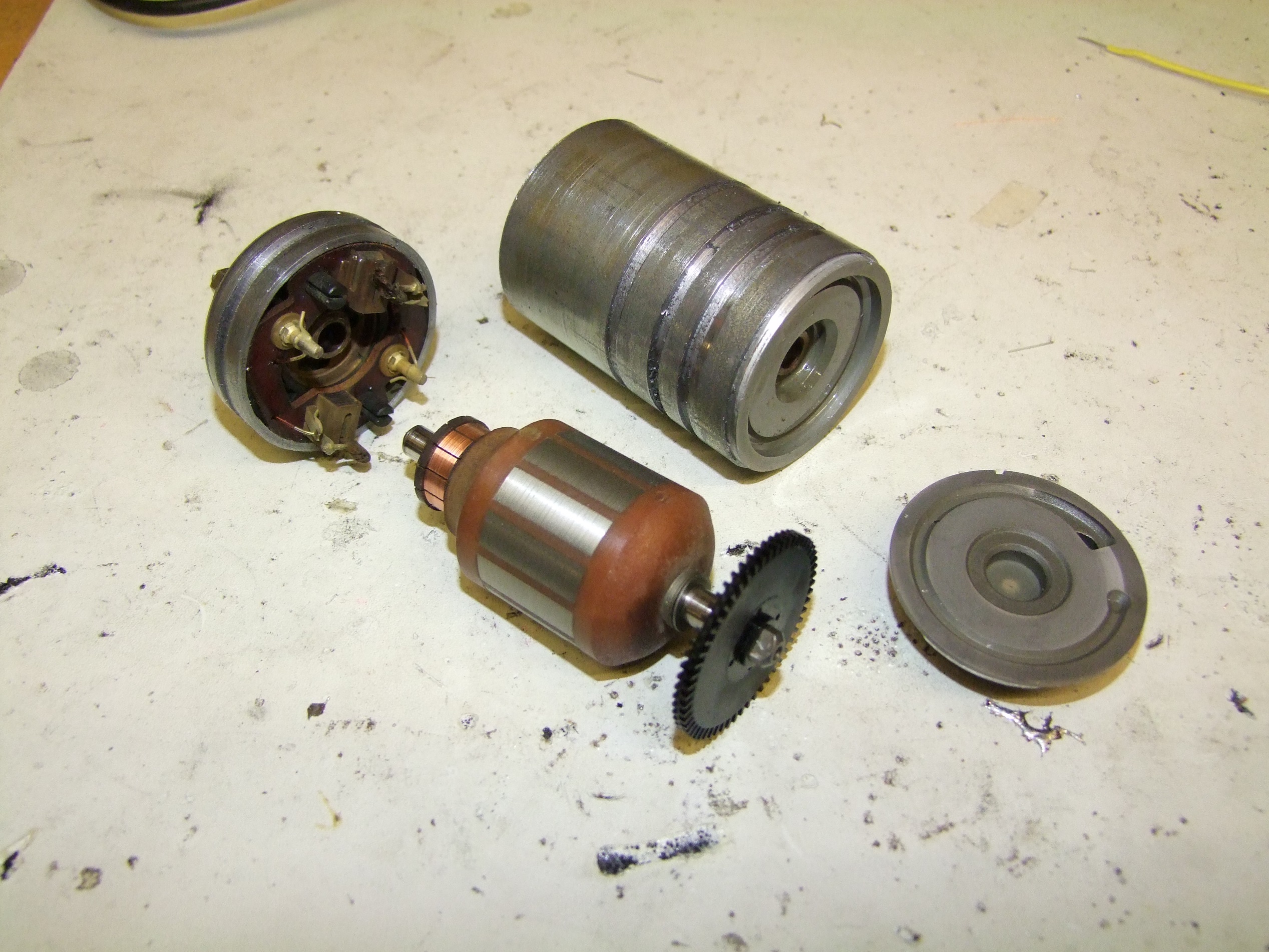
I proceeded to machine this thing apart using a metal lathe:

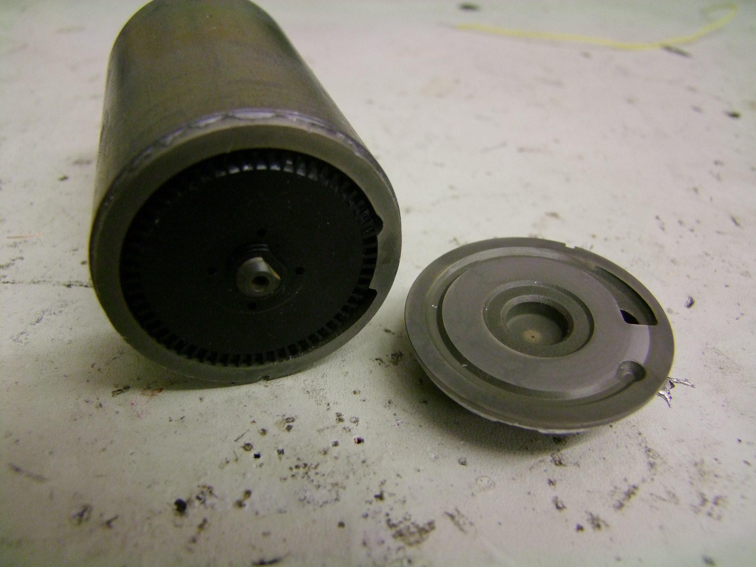
First to get popped off was the end with the impeller. I just took a cutoff tool and jammed it in until something fell off. It seems pretty normal here. A volute shaped chamber and a many-blade impeller.

Many cuts later, I popped out the rotor of the pump. Okay, it really is a brushed DC motor running submerged in a bucket of gasoline.

Now, I know this is actually the best possible place for such a thing, surrounded by cooling, nonconductive, non-ionic fluid, above its vapor explosion limit, that carries away the brush dust wear… In the grand scheme of things, it isn’t bad. But you know that trope that says you know obscenity when you see it? Well, this is obscene. I’m now afraid of every car that drives by.

Inspecting the state of the commutator and brushes, I concluded that the fuel pump motor itself was nowhere near failing and could have run for many more miles. However, not knowing the service interval of this part, I’m still satisfied with its replacement.

I’ve replaced about all the subsystems that can be replaced now. What’s next? I suppose I have these little boxes full of driveshaft U-joint parts… or I could go do more bodywork.