All of my projects go through periods of ups and downs. I either end up demoing them too hard, or they get “temporarily” parted out for some valuable component only to never get put back together, or the weather stops being terrible. Given that the winter is letting up and the sun has emerged above the horizon, it’s time to think about the small silly electric rideables once again.
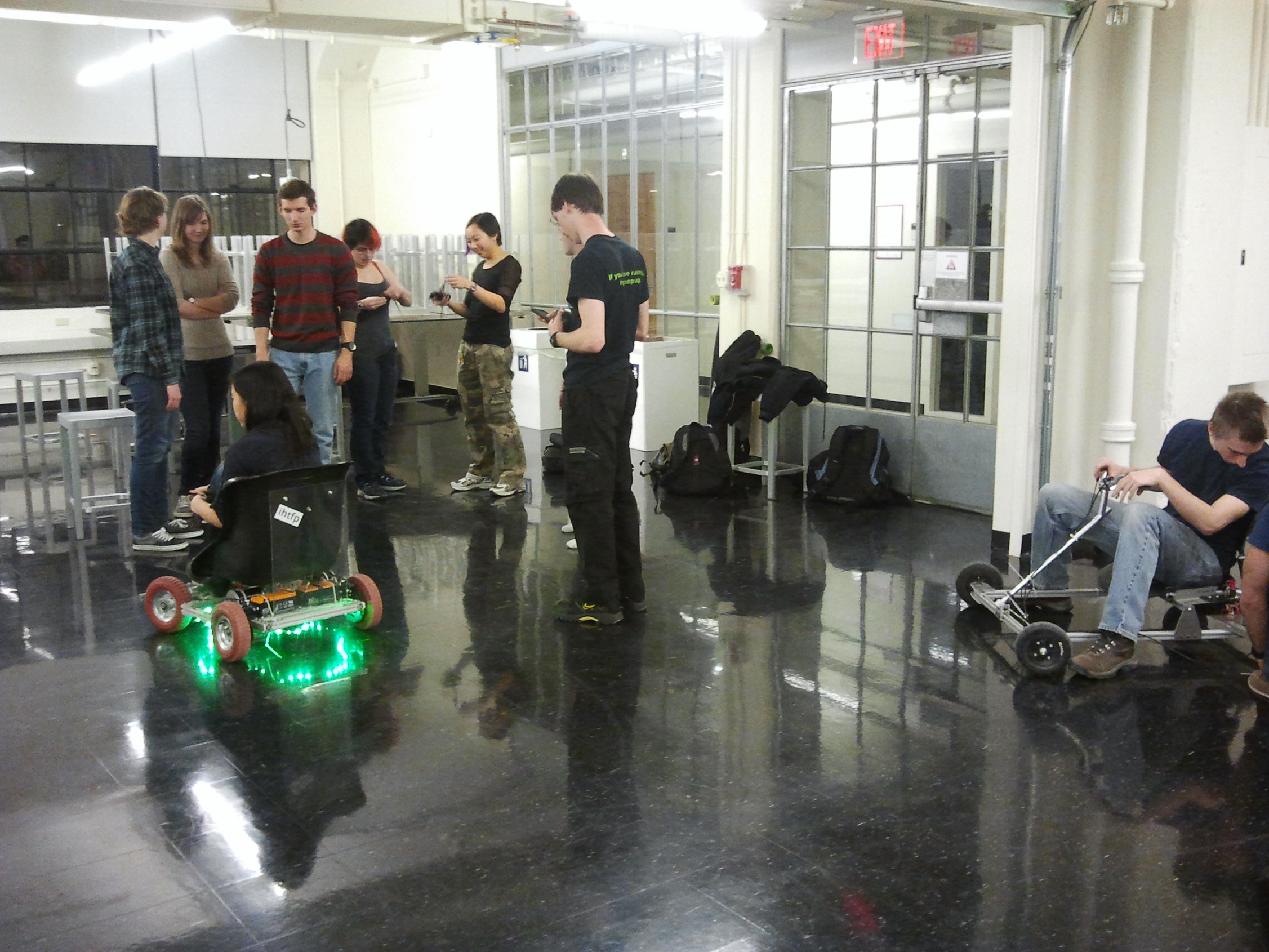
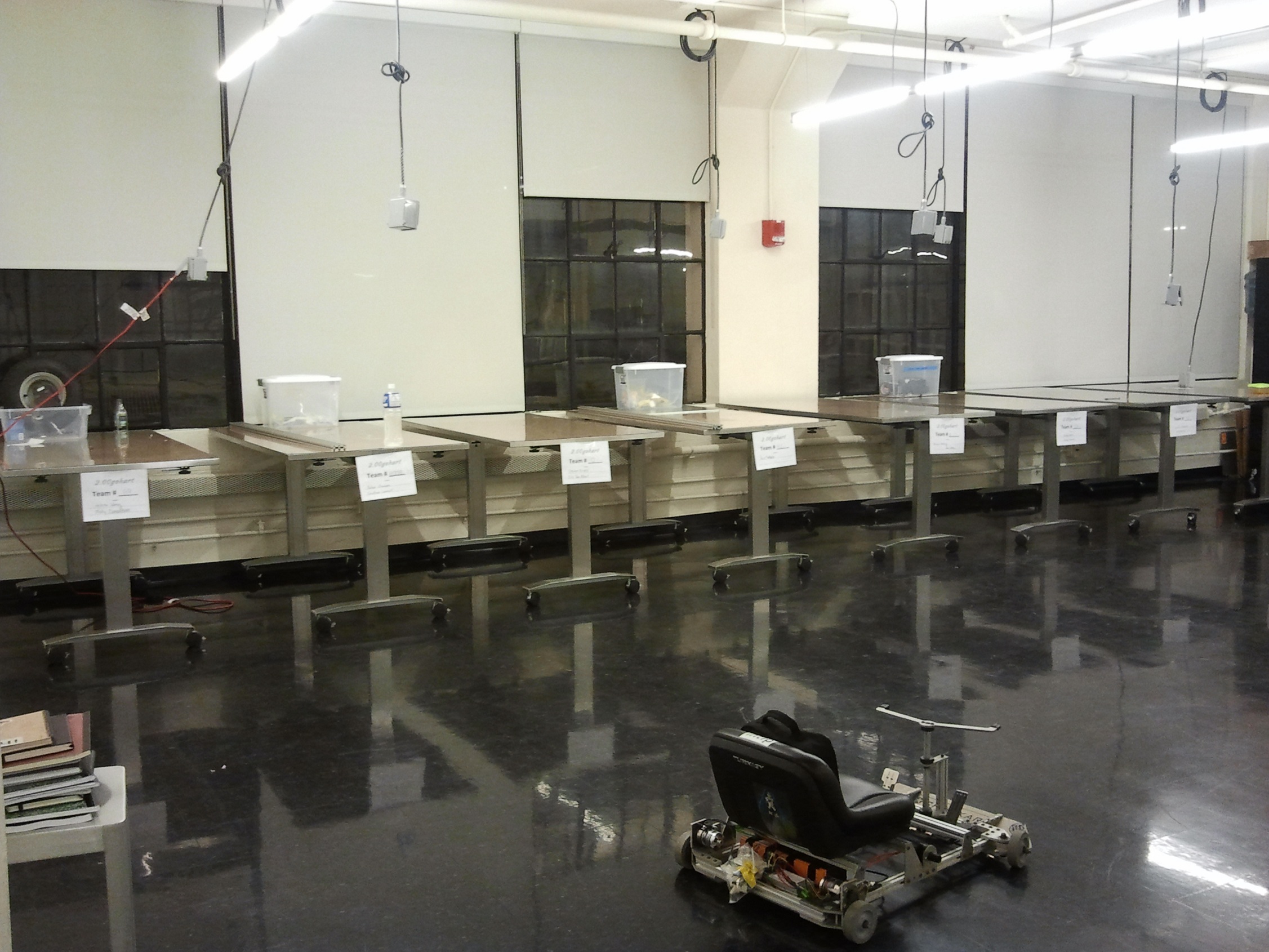
Almost a year after its construction, the story of Chibikart has played out not unlike many Hollywood celebrities and pop icons. After a meteoric rise to fame based on a single hit. which spawned a wannabe or two, Chibikart bungles a live performance but pulls it together just enough for the next show (At the bottom… though I still stand by everything I said in that dribbling polemic). Afterwards, however, Chibikart is never really the same, and sinks into a life of decadence and smoking magnet wire enamel. With my desire to never rewind those damned hub motors again, it seemed like Chibikart was doomed to live under a table forever:

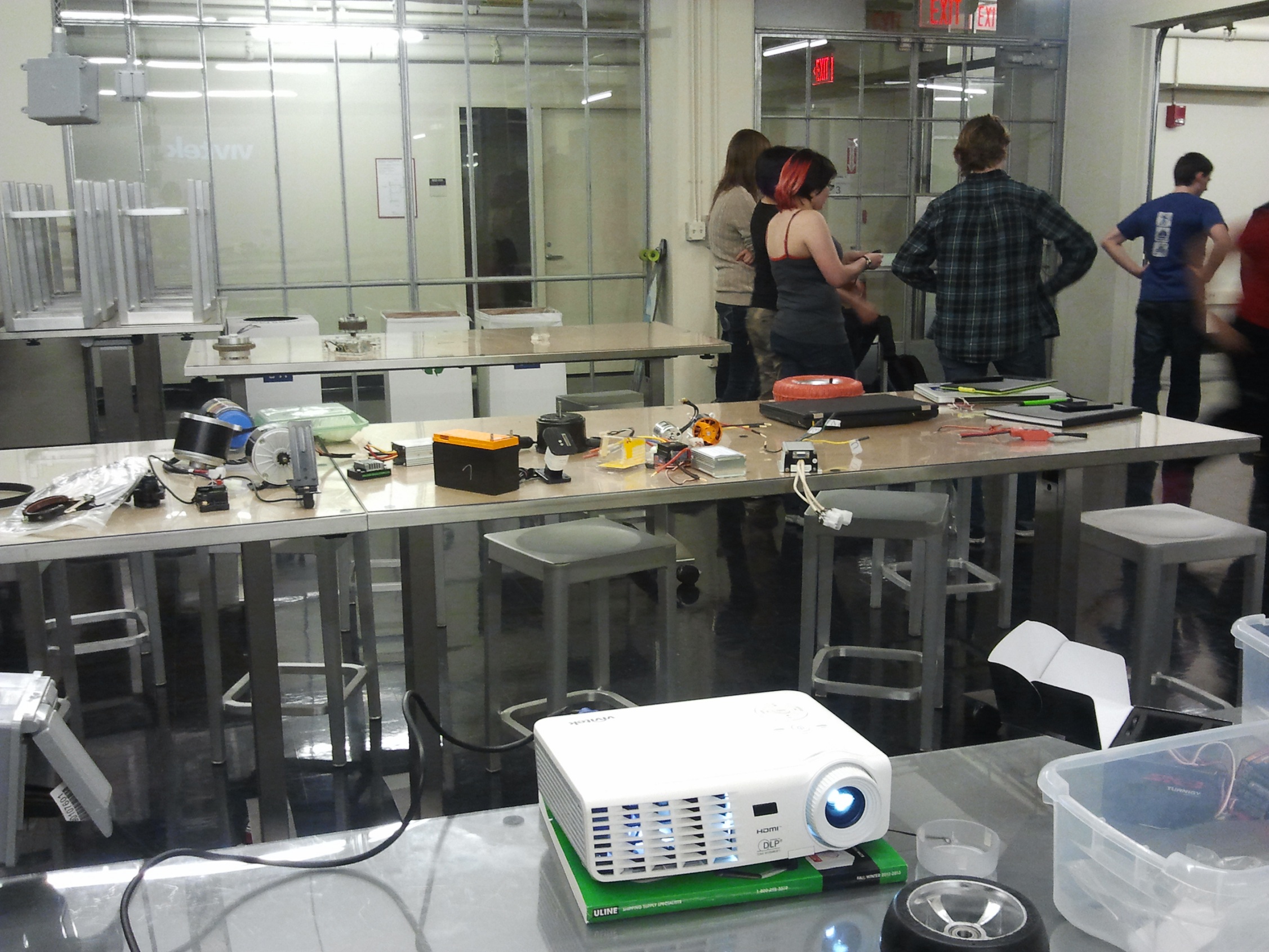
…with his washed up co-stars…
But another season of 2.00silly-rideable-thing dawns, and as such, I must have an Instructor Vehicle. The Instructor Vehicle is totally out of spec and over budget, because Instructor Privilege. I had to decide what to do with Chibikart. It was easy enough to start on another bunny-brained scheme since I have more than enough parts to conceive any rideable, drivable Eldritch abomination, but when I had the semi-working hulk of one of my projects sitting right there taking up space, I found it hard to justify anything else.
So what do I do with it? This was an equally hard decision. I could just rewind the hub motors one last time and be done with it. Chibikart is actually quite fun in hub motor form. I could make, instead, 4 kitmotters to demonstrate the concept in real life even better – one of the ideas on my Infinite Time*Money Back Burner is to make a to-spec Power Racing entry using Kitmotters, since machine time and labor are not budgetable items.
One of my favored ideas from the beginning was to show how to do a sensorless drivetrain “right”. I spent much time in 2.00gokart scaring students away from using R/C style controllers because of their notorious unreliability and lack of current limiting and start-from-zero predictability. Yet at the same time, I wrote an entire section on this in the latest Scooter Power Systems instructable.
The way I see most people use R/C motors with sensorless ESCs in vehicles is in direct contrast to the guidelines mentioned in the Instructable. They’re generally the biggest (or bigger than necessary) motors you can buy, hooked up to a low or moderate gear ratio calculated from load necessity or cruising speed. While this is perfectly fine for DC motor drivetrain design and also sensored BLDC/AC motors, with R/C controllers it’s just asking for trouble. Huge current bursts will be drawn during the starting regime because the motor might not “start” in the right direction, or if it does, needs to expend tons of power to produce the torque needed to accelerate. More often than not, the first thing that goes is the motor controller, since they’re invariably small and unprotected. It’s been my assertion for a while that a 50mm class R/C motor (typically 1500 – 2000 watt) is more than enough power, if used correctly, to move a person, but usually I see people gunning for the bigger 63mm and 80mm motors. Hell, that’s even what I run on Melonscooter. And precisely like I warned against, I go through motor controllers like crazy and really shouldn’t try using all 6000+ watts of power – it’s literally enough to get me to highway speeds and I have enough fun already flying by parked cars at 20-25mph.
So, perhaps a more noble goal is to troll everyone by making a properly proportioned sensorless R/C power system with typical hobby parts. I’d pair a 50mm motor with an oversized (for overhead) R/C controller, but instead of gearing sensibly and picking the slowest (highest torque per ampere of current) motor, I’d head the opposite direction: An unreasonably fast motor coupled with a double-digit gear ratio. Remember, R/C controllers love to spin things which are going really fast. In the combat robot world, this technique has a nickname: “Gene-ing” it, based on the habits of one particular builder to overvolt small outrunner motors dramatically and gear them down very low to get tremendous power into his weapons. The whole idea would be to divide down my apparently inertia to the motor so far that even the jerk the controller gives it is enough to move me a little.
I next spent some time on two sites. The first was Hobbyking, shopping for potential motors in the 50 to 60mm range. The second was the still-very-useful Torque and Amp-Hour Calculator whipped up for roughing out Battlebot drivetrains over a decade ago. I was aiming for a few goals, in no particular order:
- Top speed of about 20mph at my desired system voltage of 37v, to try and conform to at least one of my own rules!
- Gear ratio in the 10 to 20:1 range. Something easy to accomplish with two relatively simple stages – such as 3:1 and 4:1.
- Wheelspin current of about 100 amps or less. This was important – I wanted the wheels to actually break traction at a current which I could find an R/C controller to run ‘continuously’. I mentally derate these things by a factor of 2 or more when juggling numbers. This means that the wheel should never just fully stall out
What this came down to is if I apply a step throttle input to 100%, the motors will have a high enough mechanical advantage to start consistently each time, and as soon as they do, they have enough torque to just break traction.
That‘s my current limit. Doing a burnout. That’s how it should be.
Hence, this project was named BurnoutChibi.
motors
At the end of the night, I arrived upon my component choices:
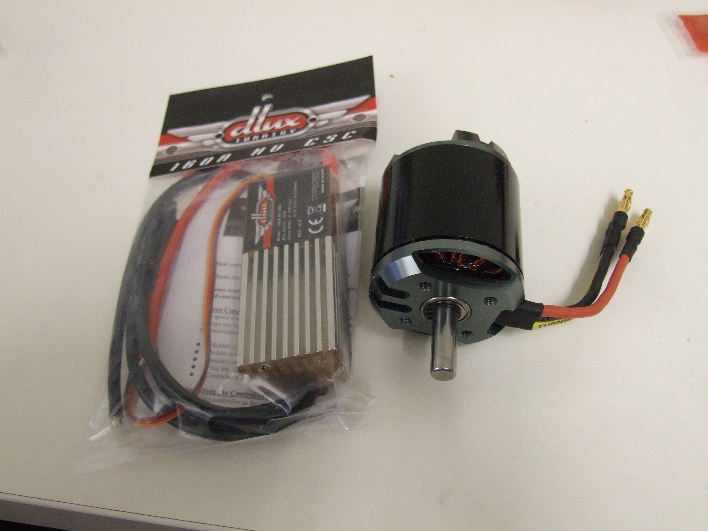
On the right, the NTM 5060/380kv. This was pretty much the only thing available that satisfied my requirements – any slower and I was going to go back into undergeared startup nightmare world, and the few motors that ranked higher in RPM/V in this size were very expensive (by comparison) “competition” motors. The cost of the motor? $36.
I’ll be amazed if it stays together.
On the left is a Castle Creations Hobbyking “160A HV” controller. Gee, it sure looks an awful lot like an older Castle controller – I’ll call it the Sand Castle!
These things have piqued my curiosity for a while, but I’ve never really bought one to chop up. It turns out they are thermal epoxied together anyway, so it’s not like I can chop it up without permanently breaking something. I blame Apple.
While I could have gone with my usual trusty Sentilons (which I know the operating characteristics of well, have decent startup ability, and enough FETs per bridge to let me sleep at night), I decided to take this opportunity to try something new. If the Sand Castles fail, I have 4 left over Sentilon ESCs from the late and great Deathcopter project. The reason I’m running 37v (10S lithium polymer cells) is because I have two giant 5Ah 10S “sticks” left over from the same project. These Lipos are big enough to beat someone senseless with and probably light them on fire at the same time. You R/C aircraft people are nuts.
Two of those packs ought to be plenty to feed two NTMs flying at top speed. Oh, I’m sorry – did I mention I got 2 sets of the above?
tires and brakes
To dump multiple thousands of mechanical watts onto a Chibikart drivetrain would result in the tiny, stubby caster wheels being ground into a pile of elastomeric powder. I’d need something vulcanized and beefy to stand the increased power, but I also didn’t want to go to 8″ pneumatic tires which are the most common size for small EVs. It just wouldn’t fit the character. Chibikarts have to have small wheels.
I decided to try and get some 6″ pneumatic caster wheels. The 6″ pneumatic wheel is something which should exist, but is difficult to find; when it is found, it’s generally expensive and part of a caster already. Harbor Freight doesn’t sell any, and McMaster is generally unhelpful and ambiguous about which one of their 6″ casters is actually pneumatic. For the record, I have a sample of 2717T41, which became the basis for my hunt. I figured if McMaster sold it, there was a cheap and generic verison of it somewhere.
The answer came from Northern Tool, a Harbor Freight function-alike of somewhat higher market segment. They have a 6″ pneumatic caster wheel replacement for Somewhat Less Price. I went ahead and snagged 4 to see if they were identical.

Also pictured above is a 90mm drum brake I got from Monster Scooter Parts. One of the missions I set out right away to complete was to find a good front wheel brake solution. While both Chibikarts have had rear brakes, this basically precludes the chance of doing any burnout whatsoever. The last time I could do a brake standing burnout was LOLrioKart, and I kind of miss that.
I started out trying to find a small enough disc brake, since I prefer those when I can fit them in. The smallest disc brake setup available stock is 120mm – a bit under 5″, which would have been too close to the ground; I’d be riding on brake rotors if the tire ever went flat or someone bigger than me got on this thing. While I could have just machined a custom brake disc, I decided to be adventurous and see what a cheap scooter drum brake is like. I have plenty of experience with cheap scooter band brakes on front wheels from LOLrioKart’s first front brake attempt, which ended with me discovering what the Capstan Equation meant in real life (Band brakes grip extremely asymmetrically with respect to direction!)
I settled on these and got some samples because I haven’t ever seen them before and was interested in exploring a new part For Make Better Glorious Nation of Silly Go-Karts. It’s my understanding that drum brakes also grip asymmetrically, though to a much lesser degree than band brakes.
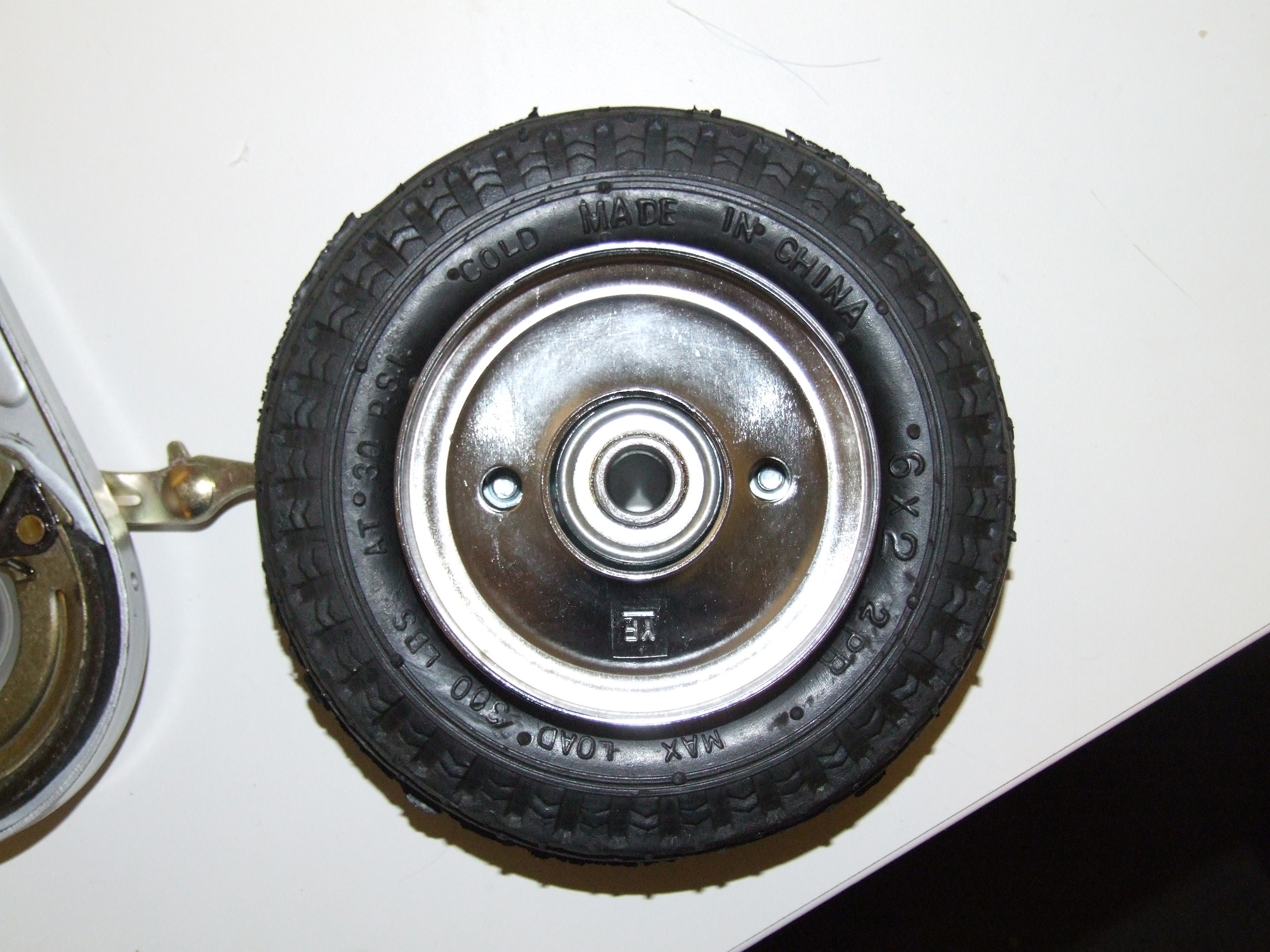
As luck would have it, the two spanner wrench holes on the drum line up pretty much perfectly with the hub lug nuts on the wheel. Well then – that pretty much seals the deal.
What I’ll probably do for attachment is make two standoffs that replace the lug nuts with posts I can screw the brake rotor in from the other side with. Two of them will have a pilot “lip” to seat in those holes. I’ll shim up the bore to be concentric, then drill the other two holes using the wheel itself as a template. I’m sure two standoffs might work, but using all four possible locations is just more robust.
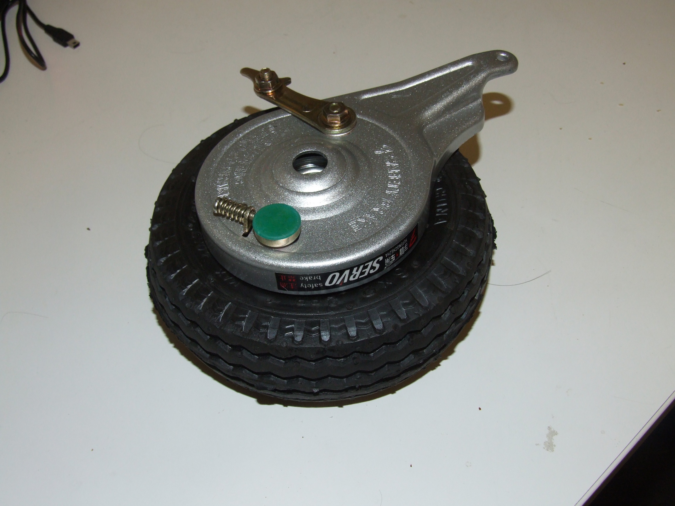
This is what the assembly would look like in real life. Instead of using the long built-in torque arm, I’m going to cut it off for compactness and instead mount the brake body itself with a circular bolt pattern. There appears to be enough space between the stamped housing and the brake shoes to drop some #10 or 1/4″ button-head screws into.

I went ahead and made a representative model of this assembly in Inventor. The bore of the brake housing is 14.5mm, so to use with a 1/2″ axle, I’d have to make another spacer with a seating lip.

The next thing to do was to take Chibikart 1’s CAD file and rip everything the hell out of it. Structurewise I was going to turn this into a DPRC, which I engineered a more robust brake pedal for.

I started adding in the new wheels and testing steering geometry, but soon ran into the curious issue of Chibikart being wider than it was long. The pneumatic wheels and brake combination were threatening to push the width out to 30″, because they were just so much wider than the skate wheels!
Some innovative compacting on the steering linkage was going to be needed.

I pushed in the “ears” on the frame a half inch or so, such that the flanged bearings were almost against the 80/20 side rails. Instead of a DPRC-style spindle which is a bolt embedded in a block made of stacked layers, I went for ultimate compactness and designed the spindle blocks to be made from 1″ aluminum square. Like the current arrangement on Chibikart 1, the ‘axle” is a bolt which is tightened into this block.
The hard part was the steering linkage itself. Part of the reason why I made the ‘ears’ so far out in the first place was so I could get enough linkage travel before the ball joint hit the frame. With scooting the steering axis inwards so far, I would only have gotten maybe 15 degrees of wheel travel in either direction. Besides seriously messing with the steering linkage geometry, the other solution was to move the linkage out-of-plane with the frame. I decided to try this first. Basically, the spindle block is solidly connected to the kingpin (which is now a hex head bolt), and on the other side, a big crank arm with a hex bore cut out of it sits like a wrench over this hex head, retained by an axial screw (not shown). This way, the linkage is moved fully under the frame and I can once again have proper steering geometry without compromising angle.
This configuration might in fact offer too much angle – there’s not a physical hard stop in the system any more, so I might actually add something else later to prevent linkage overextension.

Back on top, I spent a while editing this sheet metal part in-assembly to get the lineup of the cable anchors correct. This plate is essentially an extended version of the “endcap” found on DPRC’s front wheel spindles, with a bolt pattern that engages the spindle block. The mounting bolt pattern for the brake housing, not yet shown, will also be put into this part.

I whipped up a quick 4.16:1 gearbox using VexPro gear models. Vex has gained my interest immensely after debuting their new line of “bigger bot” parts this Spring for the 2013 FIRST season, ostensibly to compete with the likes of AndyMark because FIRST is now big enough to sustain two parts houses. I actually have a VersaPlanetary box bought completely for the purposes of dissection, and intend on writing it up for Beyond Unboxing one of these days – they’re nice, I must say.
The NTM motors have convenient 8mm shafts already, so any gear that can go on a FIRST CIM motor can be fiddled onto this one.

The new rear end of BurnoutChibi nee Chibikart 1 is basically a DPRC back end with a different motor adapter plate. This time, the 4.16:1 gearbox hovers above the main 3:1 chain drive, with the usual chain tensioning method. At this 12.5:1 ratio, the top speed is right at 20mph and the per-wheel burnout current is something like 80 amps. Not bad, but not exactly good either.
So right now, Burnoutchibi is essentially DPRC on some serious roids, with pneumatic tires. By itself, no matter what, it’s not that exciting any more – I’ve built enough things like this already. And by this point, it’s maybe a little hackneyed. The next post will be about what I intend to do about that…