Since the beginning of televised robotic sports history, combat robot builders have been repeatedly asked by fans, enthusiastic onlookers, and bright-eyed newbies, a variant of the following question:
D00D WHY DON’T YOU PUT LIKE A BUZZSAW OR SOMETHING ON YOURE ROBBOT SO YOU CAN LIKE CUT RIGHT THRU THE OTHER GUY AND SHIAT????
Good question. Why haven’t we? Sawbots are conspicuously missing from the combat robot hall of fame. Everybody wants to see them, but there have been comparatively few saw weapons built in all of the history of robot combat, and even fewer ones which actually achieved its end goals. Minion, the most famous saw-wielding Battlebot, replaced that weapon with a kinetic energy disk starting in Season 3.
So why is this the case? Saws need a delicate balance of torque and speed actually cut something. Too much of one or the other, and you either blunt off the teeth or jam it in the opponent. Essentially all saw weapons to date have been directly driven or geared very fast from a (comparatively) low-torque electric motor. That means they can scrape and spark nicely, but actually laying into an opponent will stall the blade.
The other element missing is controllable pressure. It’s difficult to cut consistently in the same place on something that’s flailing around or moving. A saw that sticks out the front of a robot but is otherwise fixed has no control over how quickly it can advance teeth through opposition armor. If it’s simply jammed into the opponent, then the torque required to actually crank the blade teeth through the material becomes phenomenal. Most saw weapons extant today rely on the stored kinetic energy in the saw to deal out damage.
This particular aspect was what inspired me to think about the Sawbot Conundrum when I was watching old episodes of Robot Wars featuring the house robot Dead Metal. Observe how effective the saw is on Dead Metal from the 2 minute mark onwards here. Dead Metal works because it is able to trap the smaller robot in its pincer jaws so they can’t move. The saw also advances on a linkage at a modest pace and has plenty of horsepower to back it up. It can actually cut things.
I immediately wondered if I could replicate the function in a smaller class, say, 30 pounds. Control of the opponent is the dominant trait of Überclocker, but it doesn’t really have a means of doing… well, anything else. I wanted a complementary Überclocker which trades off some of the control for more ownage.
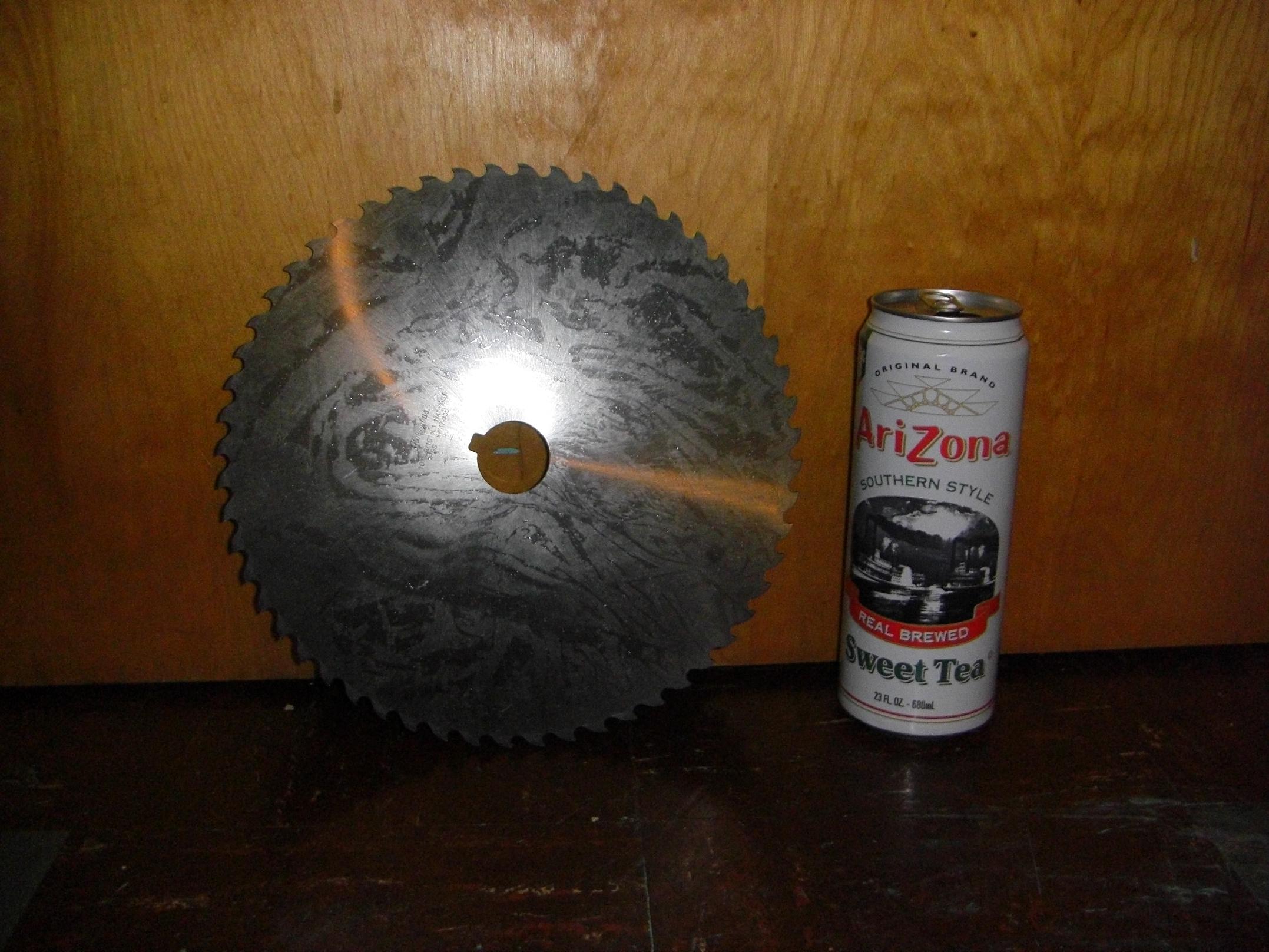
In an alignment of mechanical planets, I was swiping some more slitting saws for MITERS off Ebay when this mutant blade showed up in the listings. I didn’t even know they made “slitting saws” this large. It’s a 10 inch blade, 3/16″ thick, and weighs a solid 4 pounds. The bore is 1.25″ and keyed.
Now I was practically obligated to build a robot around it.
To drive a saw this large would require immense torque. I investigated planetary and spur gear reductions before deciding that neither could satisfy the torque transmission requirement, be minimal in weight (spur gears were totally outclassed here) and also be easy to build or cheap to buy (there go all planetary gearboxes in existence).
Luckily, I remembered that I had…
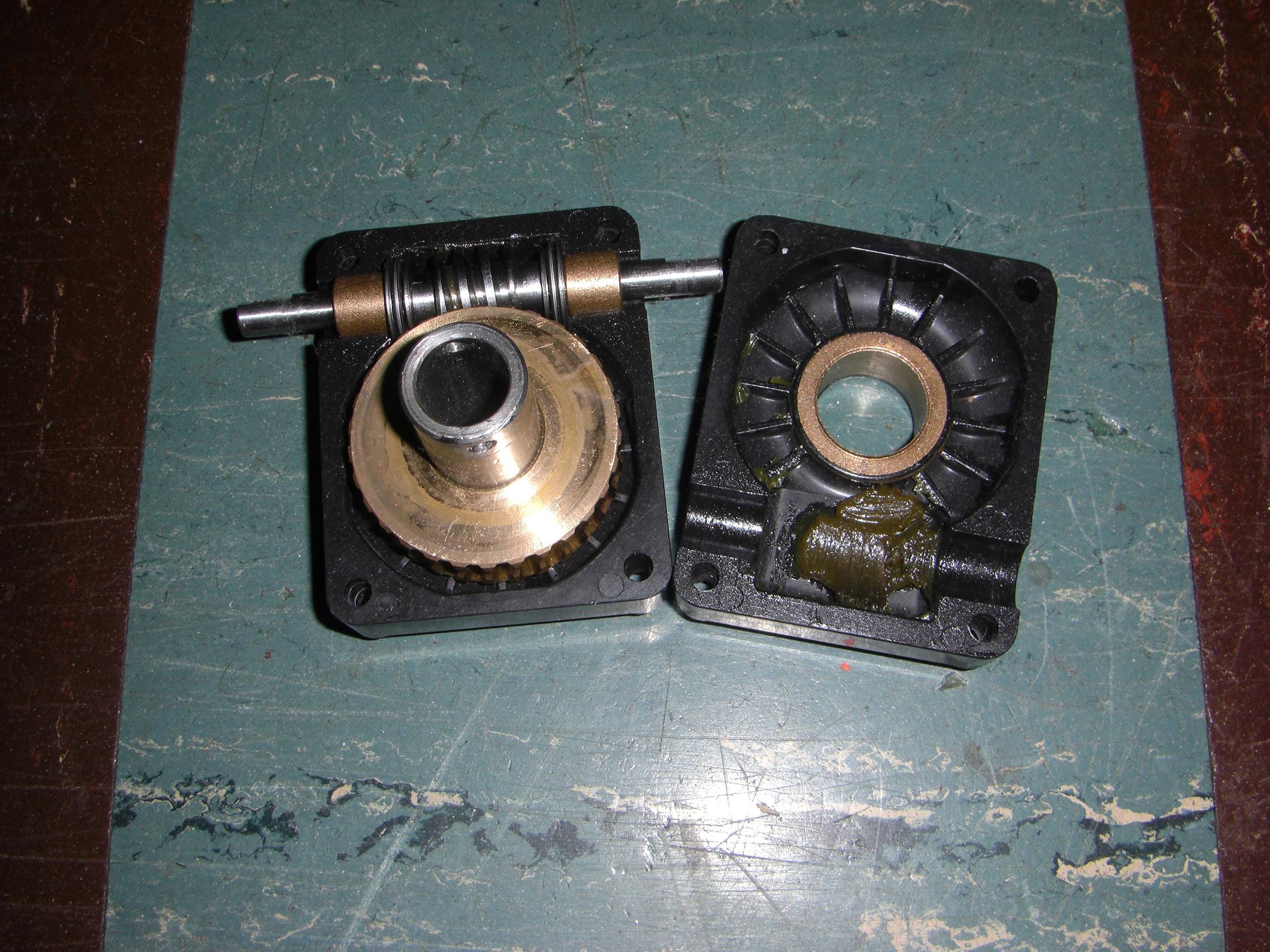
…this worm gearbox that I scrounged out of a pile of discarded lab cleanup materials. It came of the base of a nicely waterjetted and assembled robot arm that looks like something heavy ran into it – or, more likely, it ran into something heavy. Either way – free 30:1, 12 (ish?) pitch single-enveloping worm gear.
While worm gears are notoriously inefficient, it’s much easier (in today’s world of brushless one-upsmanship) to dramatically over-motor a weapon to compensate for that. Worm gearboxes are probably the most common things in industry, also, because of their simplicity, compactness, and durability. If you don’t mind the less-than-peak efficiency – which \m/assive \m/etal generally doesn’t – then why bother with something else?
There do exist machine tools which use worm gear driven circular saw blades to cut metal, generally competing with bandsaws in situations where edge finish and accuracy are important.

They are known as cold saws, named for the fact that they use a toothed steel blade to generate chips of material instead of a disc of abrasive rotating at high speeds. I like them better than bandsaws, because I can hang off the handle on the largest cold saw in the shops and take down a 4″ solid round of steel in under 30 seconds, and that’s just too awesome.
Thus the inspiration for Cold Arbor was complete. The name is both a play on cold saw and the Battle of Cold Harbor, one of the “bloodiest, most lopsided battles” of the American Civil War.
Anyways, I love my found object gearset, but that janky plastic case has to go. Why put such nice gears in a plastic case?
Oh, right – nobody is expecting me to hang a 10 inch sawblade off one. Using the existing mounting dimensions, I designed this preliminary gearbox case, to be made of aluminum. Some 7/8″ bore ball bearings will take the place of the bronze bushings. Since the shaft is hollow, a large bolt running through the center makes for easy blade mounting.
So here’s the first try at the actual blade assembly. This is more inspired by a sliding compound miter saw. The premise here is to reach the blade as far into an opponent as possible. Using a plain swinging saw, the maximum “cut depth”, so to speak, is limited to the saw radius minus the radius of the gearbox. This design was an attempt to remedy that by allowing the saw to “reach” further by sliding.
The prelim design more progressed, showing the prospective linear bearing rails. This was about as far as the design ever got before I realized it was going to weigh far too much, and would suffer from stiffness issues. So that was scrapped.
The truncated circle floorplan begins to make a return here.
Crazy design number 2 uses a six bar(!) linkage that allows the saw to retract fully into the footprint of the robot, but extend about 6 inches forward. The swinging motion bring the saw over, then down upon the opponent. The whole thing would be moved by 1 actuator, mounted at the bronze bushing and causing that part of the linkage to move about 70 degrees. The motor would remain parallel to the ground at all time.
A much more practical idea than the sliding design, but ultimately, it also faced some pretty hefty weight issues, especially after I designed in the actuator.
Alright, big leap of faith here. What the crunk is going on?
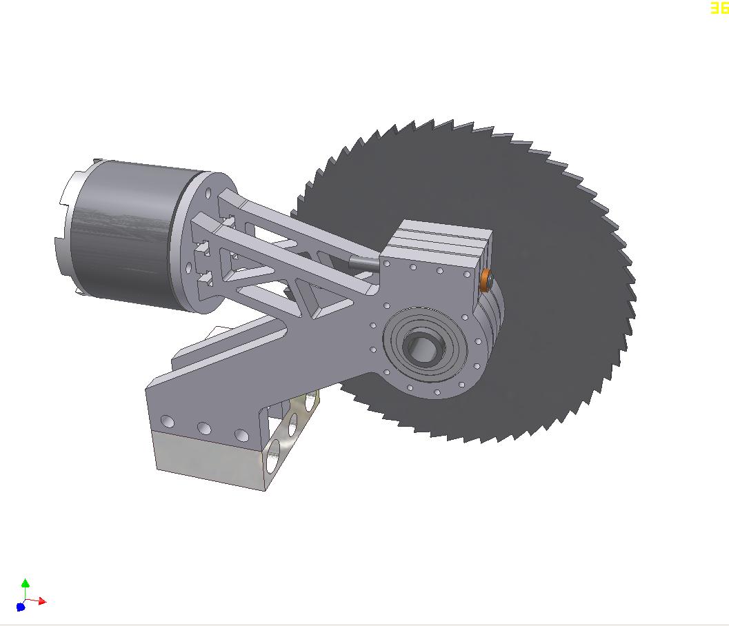
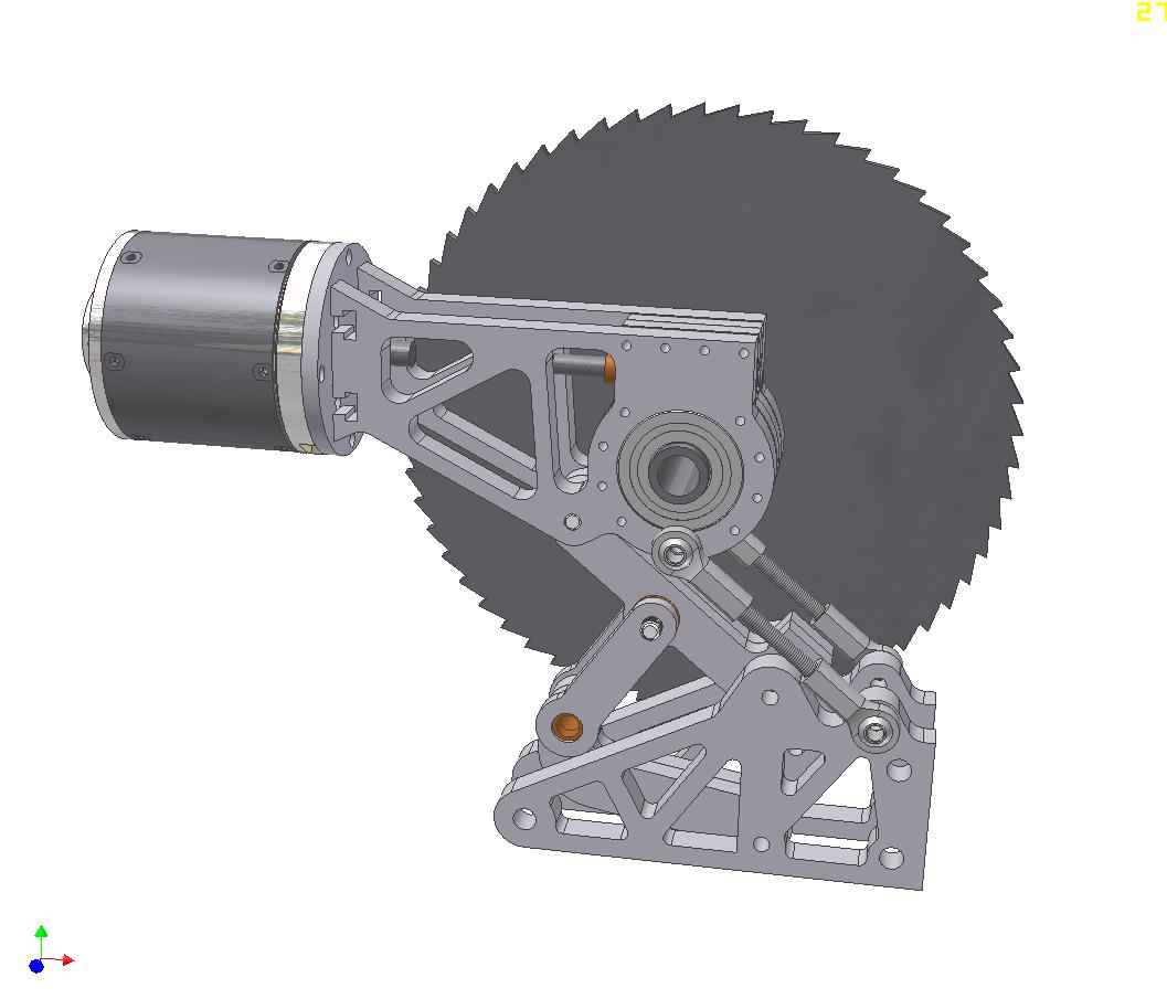
I decided to give up on a cool swinging linkage and just made a conventional linear actuated pivoting assembly. This linkage swings through just over 75 degrees of motion to bring the saw all the way to the ground in front of the robot.
The motor mount is integrated into the body of the gearbox to make it easy.
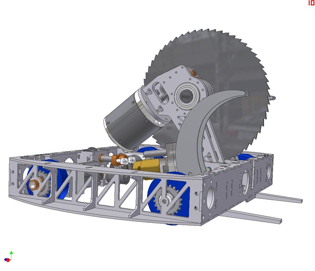
One additional component visible here is the actuator for the clamp. Both clamps are connected to the single linear actuator at the rear, so they should move (sort of) together. They are linked to the actuator nut with a ball-jointed tie rod.
A clearer shot of the clamp actuation. Notice the top claws have been replaced with a fancy to-be-welded structure.
While the claws actuate together, both clamps (top and bottom of each side) are capable of independent swinging motion. This should allow me a bit more flexibility in approaching opponents.
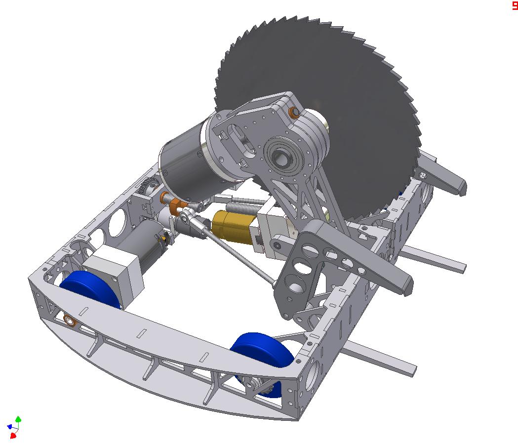
A bit more progressed now. Top and bottom cover plates will be the usual order of 1/16″ Garolite reinforced in select locations.
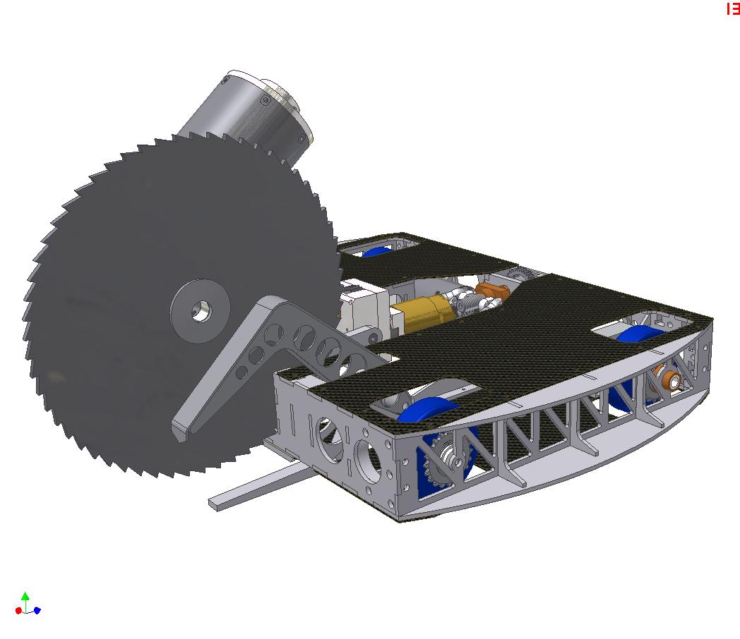
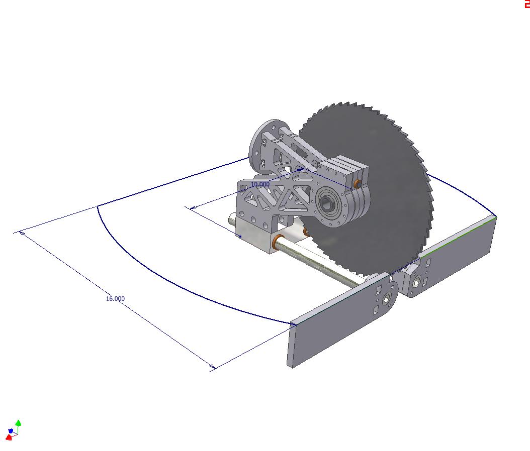
The saw in full deployed position. The bot can actually reach far enough to cut itself. To prevent this from happening, the leadscrew length in the actuator will be tuned appropriately.
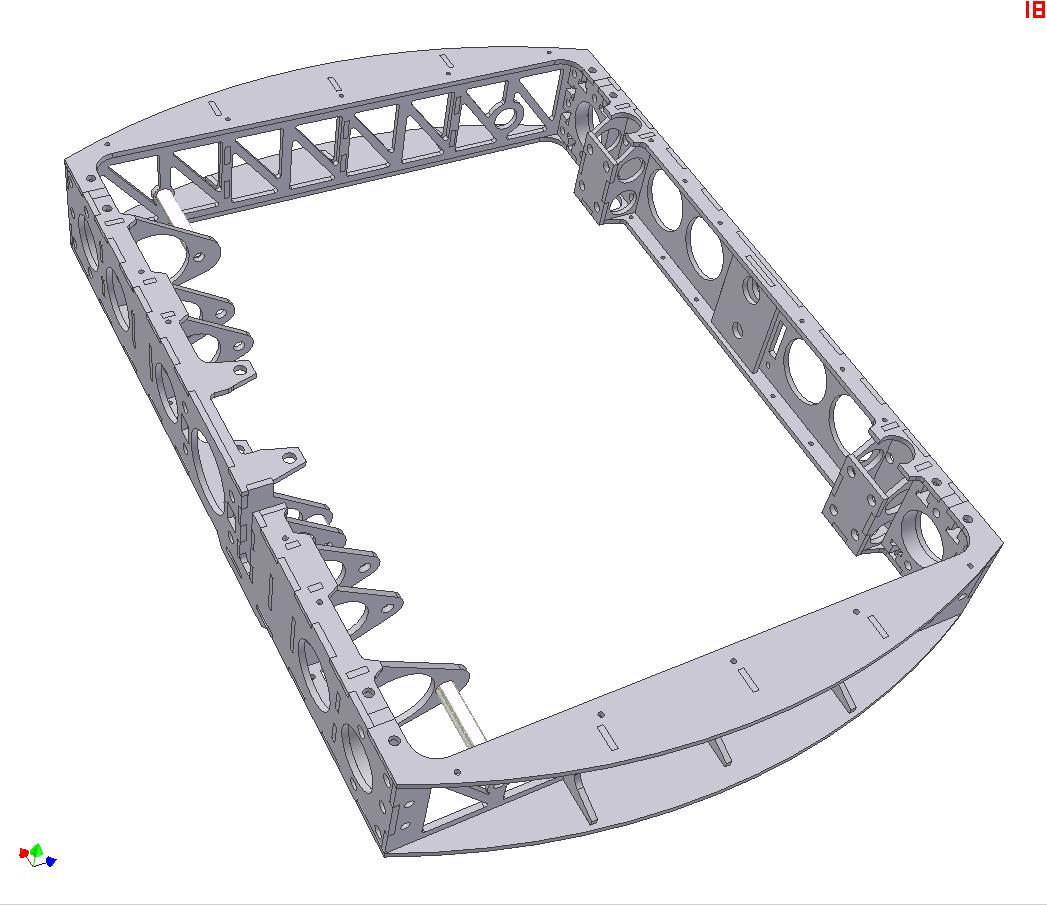
The frame of the bot will be sort of a unique first try for me. It will either be zinc-aluminum brazed or, with luck, be legitimately TIG welded. Either way, my first foray into “permanent joinery”, so to speak. We’ll see how it turns out. The robot just didn’t have the space to put T-nuts int the frame.
The frame is four pieces – front, back, and the two sides.

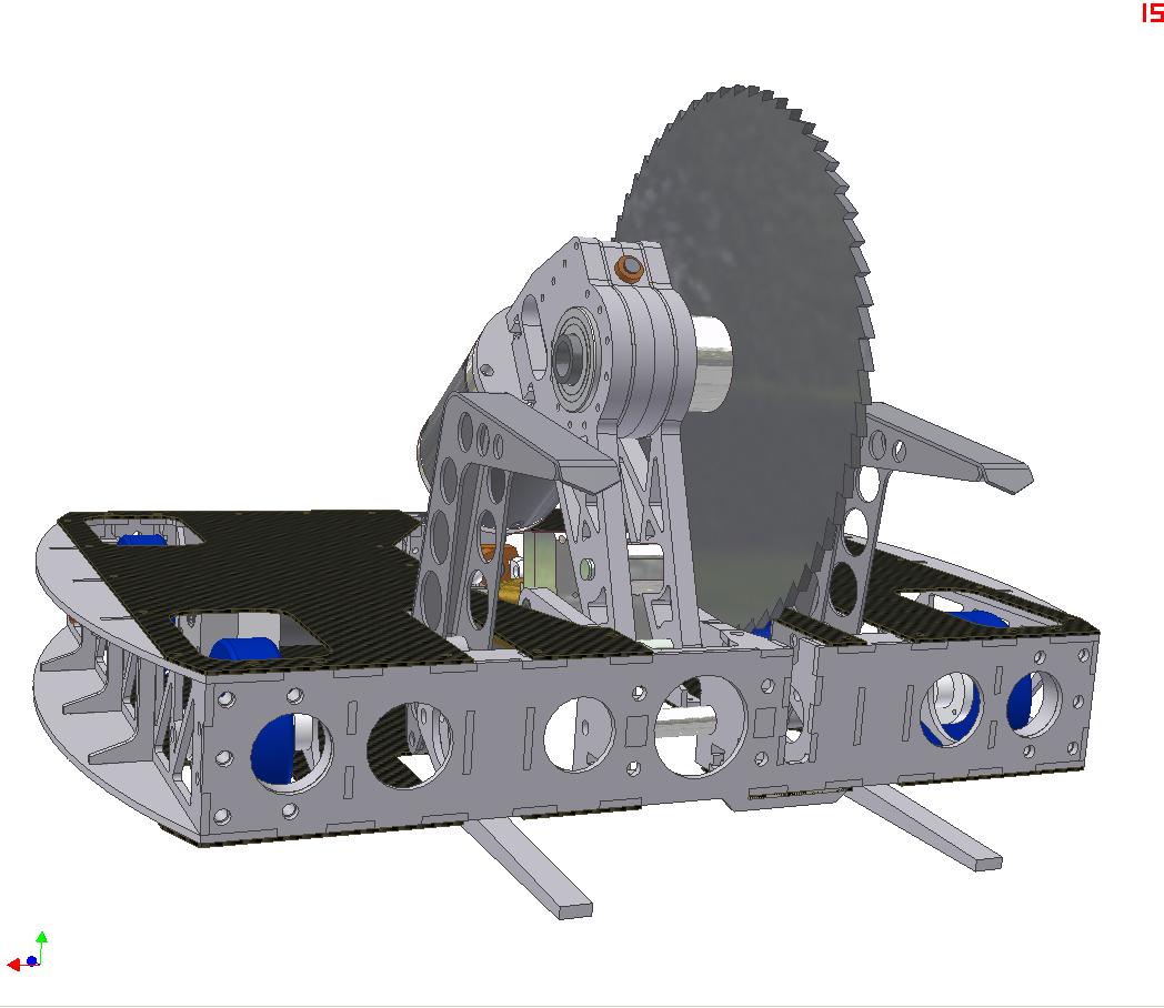
Filling out the internals a bit using AUTODESK INVENTOR 2010!!!! on my NEW LAPTOP!!!!. The fancy welded flaw is gone – I figured four fancy welded assemblies were enough for a first shot. They have been replaced by a single flat aluminum top claw. Less rigid, but also easier to make and assemble.
I plan to let this bot use the same batteries as Überclocker, since I already have packs made. 7S A123 cells yields about 23 volts nominal and 25 volts peak, which is roughly the tolerance level of the Victor 883 controllers anyway. I have leftover 883s and 884s from Clocker.
Electronics will be mounted on “cards” in the body. Not really for quick access and removal, but there wasn’t a way to mount everything horizontally.
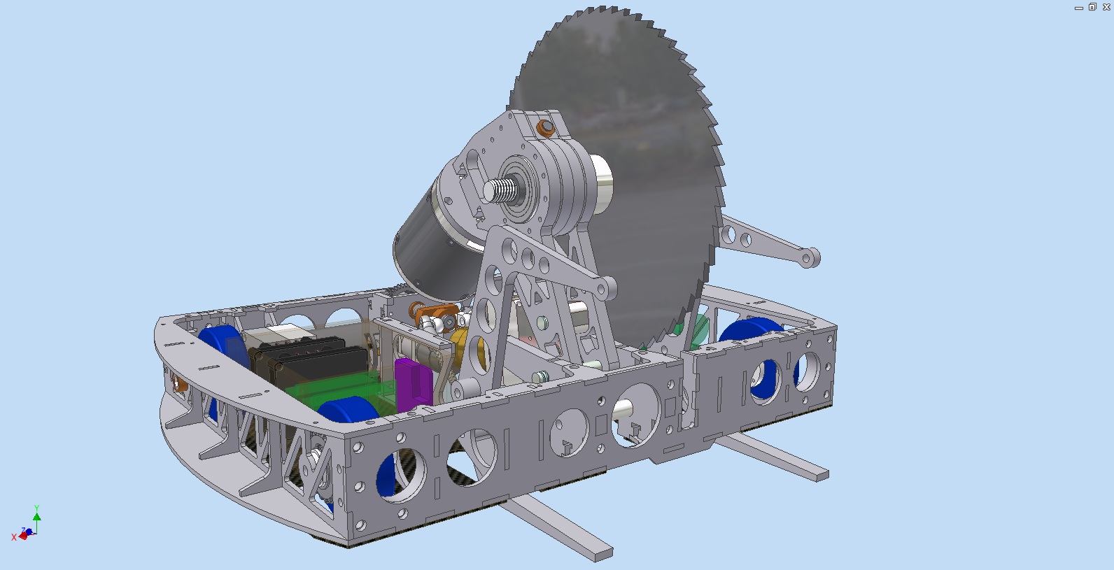
A beauty shot of everything so far.
I discovered the animation module of Inventor and briefly played around with it. Here’s a cool CAD video of the robot mechanisms in action.
The schedule for completion is “ultra fast-track”. I managed to put together most of Clocker in two weeks, so this robot should be no different. Let’s hope I’m right.
HERE WE GOOOOOOOOOOOOOOOOOOOOOOOOOOOOOOOOOOOOOOO
Vroosh!