Wow, how’s it almost the middle of August already? You know what this means?

That’s right. Basically, for the past few years, every late July and all of August has been spent rage-prepping robots for my annual robot party that I’ve gone to compete at since…
2003.
Holy shart, this one better be good then! And what better way to make it good (…besides having functional robots for once, I mean…) than returning to the 12lb class from whence I came?
It’s been a long, long time since I had a functional 12lb class bot. My parting shot at the class was in early 2008 with Test Bot 4.5 at Motorama 2008. At the time, the NERC Sportsman 30s were just barely becoming a thing, and after that event, I decided to participate in the class instead. The 12lb class at the time was just becoming infected with the “Brushless Penis virus”, in which builders rely increasingly on spinning larger and larger chunks of tool steel with larger and larger brushless motors, leaving the class designs polarized towards either those or heavily armored boxes without other redeeming features. Matches basically came down to who got in The Hit first and often ended with both bots being disabled or otherwise gimpy and hobbling.
It’s like being a dubstep groupie – always about The Drop, but with robots, so half the match you’re just waiting for The Drop and talking for days afterward about how brutal The Drop was while picking splinters of A2 tool steel from your forehead.
That game got boring for me fast. So, I spent my next 3 distracted years building dysfunctional versions of Überclocker, until last year when I finally seemed to manage something remotely interesting.
With Überclocker Advance seemingly performing up to snuff at Motorama 2013, and only needing very minor repairs and upgrades for this year (to be detailed soon), it was time to think of new robots. If I were actually good about sketching out my designs, what would follow is a small thesis worth of fantastic fun machines, none of which would actually qualify for conceptrobots.blogspot.com.
But what I really want is a tiny Überclocker. Ever since version 1 back in 2008, I’d wanted to scale it back for the 12lb class. This hasn’t ever happened yet since I’ve had enough fun getting the actual Überclocker to work properly. I’ve also thought of doing up a beetleweight or antweight version. Past that, the thing which has kept me from developing the idea further is that I was reluctant to build a bot for one event: Robot Battles is the only event I am aware of that has a “sportsmans 12lb” type competition – even though its own competition is much different and came way, way before the modern era of robot fights. Events like NERC Motorama would force me to run this elaborate contraption with the brushless pen0rs.
I’m not sure when I decided to actually pull the trigger on this design. Originally, I was hoping to make a grand comeback with Test Bot 5. I’ve completely designed Test Bot like 17 times over since 2008, but the basic flavor has been the same – a 4-bar lifter with a solid and fast drivetrain. Sadly, this is as far as I got on the last ‘redesign’:

Not even sure what I was getting at any more. Oh well. Those saw motors aren’t even available now.
I figured that all of my fresh-built bots will have some kind of weird teething issue if I start this close to the event, and that would be quite an embarassment to the Test Bot name. I’ll bring that back when it’s ready. Maybe having a 12lb Clocker would encourage the development of the 12 Sportsmans up here quicker – there’s been plenty of talk about it, of course, but we just haven’t quite hit critical mass yet.
Like Überclocker Advance, I jumped into Inventor and made up a quick sketch just to get the dimensions down and see what might fit where. This is where this entry will degrade entirely into CAD pictures!

This skeleton drawing was made about 2 weeks ago when go-kart season was in full swing. Part of what I wanted out of this bot was a bit of ridiculousness. After all, it’s a small Überclocker, and any good chibi version of an existing thing must emphasize its best features. This bot was going to be all fork – or at least the fork will prominently feature in the design. The body will also be shrunk into something with a higher aspect ratio for a bit of the goofy look.
I had in stock several 2.5″ “McMasterBots” wheels – the 40A type – for what I can only imagine was the next Test Bot, so I elected to start the design with this element, even though I think it would have also done great with 3″ and 4″ wheels. Some times, you just need to “ground” the design somewhere or you’ll never start. So this bot will be tall, with tiny wheels (but still plenty of ground clearance), and a giant fork.
One question I had which I tried to solve early on was what to use for drive motors. In the 12lb class, if you’re a pusher type, drivetrain-tensive bot, a set of 500-class motors is about the norm. When “hobby tool” sized cordless tools were easily available in the early and mid 2000s, four of them with their RS-380 motors made a typical first bot for many folks – and Test Bot’s third incarnation which last competed in 2005, and should still be around here somewhere, still uses them. I really wanted this 12lb Clocker to have a forceful drivetrain, since it would likely need to travel around carrying an opponent.
Speedwise, my choice of wheel size precluded using even the 24:1 single speed cordless drills – it would have been dirt slow. I was spoiled by Überclocker Advance’s near-20mph top speed and excellent handling with the 40A wheels, and I wanted something similar for this bot. I briefly considered a set of Vexboxen, but at my required ratios for direct drive (wheel-on-gearbox) it would have been too long with a motor, and would have made the bot like 16″ wide – almost as wide as 30lb Clocker.
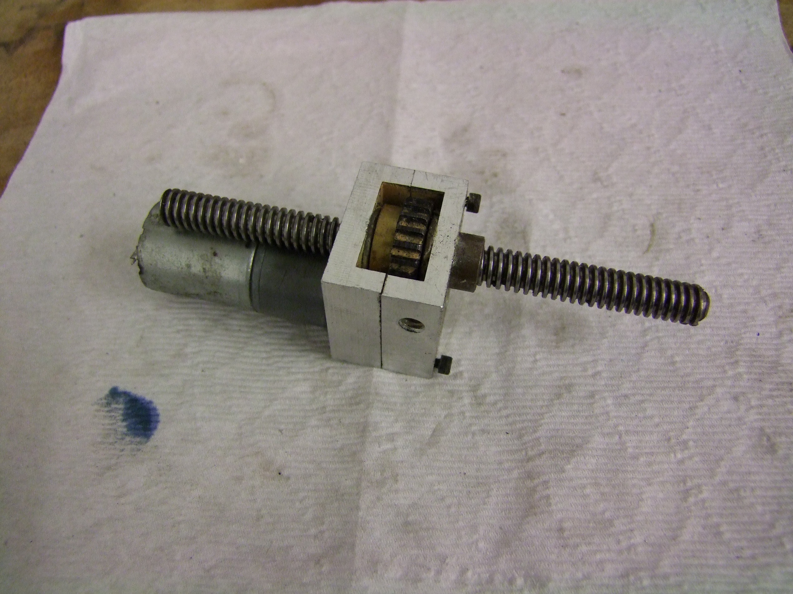
Space-wise, an external chain reduction similar to the near 1:1 indirect drive of 30lb Clocker was the most feasible, since it meant I could keep to a single speed gearbox. To minimize size, I decided to make my own gearboxes:

The hell is that? It’s what I’m calling the Angerbox. Like Vexbox and Ragebridge, and other similarly pissed-off sounding robot parts. What it really is is a 3D printable case that holds half of a drill gearbox. Similar to what I did on Test Bot back in the day, cutting a drill gearbox in half and (preferably) using the all-metal output stage nets you a 6:1 reduction. What you see there on Test Bot’s motors is a 2:1 spur stage feeding into the 6:1 planetary output stage, creating a 12:1 gearbox that gave Test Bot a nice 15mph top speed.
I plan to implement that roughly 2:1 reduction using the chain drive this time. 6:1 direct on my 2.5″ wheels would give a top speed of like 25mph, which is a little over the top, but would burn out the motors quickly.

Here’s the Angerbox placed in the frame for first sizing passes. I also drew in various sprocket pitch circles to see what ratios made sense. In the end, I settled on an external 14:24 drive, yielding, with the 6:1 planetary and anticipating overvolting the 18v motors (since I have an asston of working motors with destroyed gearboxes from Null Hypothesis) to 8S (25v), to get me a top speed of 18mph.
Why a 14 tooth on the motor? It was the smallest sprocket that had a hub big enough to enlarge to 12mm bore (drill shaft size) and have enough meat left to hold a big set screw thread. Most times, “the math” doesn’t take these physical considerations into effect – this is one of the big lessons I try to get across in my Silly Go-Kart Camp, that you can math until the end of the world but your project still must exist physically, which implies other constraints.
A 12:24 would have been a clean 2:1, but the sprocket would have been so small that attaching it to the drill shaft would have been damn near impossible without machining the drill shaft down to size (weakening it greatly of course…)

I imported the old drill parts from Test Bot’s CAD files (after cross checking with my bag of drill parts to make sure I actually had the correct types), so here’s what the mostly finished angerbox CAD looks like. The stock drill shaft will be cut down to fit in the bot. The case will be a quick 3D printed jobbie (Hey, the drill cases are originally made of shitty plastic anyway, okay?)

Using my 2D drawing as a visual reference, I started designing up the actual parts. Unlike all the Überclockers ever, this design will feature “overhung”, or single supported wheels. I tend not to favor them, but both weight and goofy looks might force me to use them this time. To make up for the single support, the axle pins are huge for a 12lber: 0.5″ aluminum to be made with my left over 7075 stock. A little bit of overkill, but the fatter the axle the less bending they experience for the same load.

At this point, I’m just trying various different layouts of parts to see what makes the most sense. The batteries, just a single string of A123 26650s, dominate the decision. I decided to make the frame tall enough such that they can stand fully upright, or else the square footage of the bot was going to increase drastically.

Hmm, I *could* make the bot longer and ditch the sloped rear to gain a bit more interior volume. This was, again, one of about 5 or 6 ways I arranged the parts before moving forward.

Another config again, still with a flat back. This was the frontrunner for a while…

Until I realized that with a flat back, 12lb Clocker was hopeless if flipped over, which it fuckin’ will be, most definitely. That made me switch back to the sloped sides, and it also made the bot’s profile more symmetrical. This design would allow the rear wheels to touch the ground just a little to putter me around for a quick escape. I’ve moved on to the more important parts now – the fr0k. Other elements such as the drive chain tensioner (imported straight from 30lb Clocker, mostly for placement and looks) and the clamp actuator have also been rough-placed.
This clamp actuator has quite a history. I made it all the way back before Dragon*Con 2008 for the the original Überclocker when my previous design failed in testing right before departure. Between this and the imported 6:1 gearbox idea from Test Bot, this bot is bringing back some serious history! The original 20:1 (or something) small gearmotor on it was stripped, so I replaced it with a 9:1 HP Pololu motor. This thing was the first custom linear actuator I built, which made me go crazy afterwards with the Cold Arbor actuators.

I’m going to stick a stock 36:1 HF type gearbox on fork duty since I have many of them and they can be easily converted to all-metal gearing because of the identical 6:1 stages. That and because I need all the reduction I can get for this dumb fork. A 60 tooth sprocket is the output stage, driven by a 13-tooth sprocket on the drill shaft.
Why 13 teeth?! This size sprocket is small enough, and the spacing of the drill motor serendipitous enough, that I’m just tapping it for the 3/8-24 thread on the drill shaft and threading it the fuck on there. A 12 tooth’s hub is too small and a 14 tooth doesn’t get me as much reduction.
With the almost-5:1 reduction from the 36:1 box, I’m still looking at 150 rpm on the arm shaft. This is something like 10 ft/s of linear lift speed. Fast enough to be used as a really bad hammer!
The motor will be mounted by some 3DP’d clamps that conform to the shape of the gearbox. I designed this part to be serviced just like 30lb clocker – four screws and the whole motor can drop out the bottom. No more removing 75% of the bot to fix one thing like last year, ever.

Getting close to the final appearance here. I’ve added a first-pass geometric model of the clamp arm. I literally picked reasonably random numbers for the rise and slope of the portion where it attaches to the fork. Brought it in, see how it looks, and change if needed.
This is, of course, another lesson I try to teach in Silly Go-Kart Camp – at some point, you gotta start putting your design down and stop trying to solve for every dimension analytically before you open Solidworks. Once you have a starting base, then you can adjust and optimize dimensions and placements based on constraints and whatnot. That’s why I just started throwing rectangles at trapezoids at the beginning.
Too many times I’ve witnessed people sitting while staring blankly at sketches on a piece of paper and an empty CAD screen, not knowing what to start designing first. The answer: all of it. Right now. Or I will fail you.
I went through quite a few iterations of the clamp motor placement, too, before realizing the best position is basically where I had it first. In this position, the motor is well out of the way of the action and the leadscrew length can be kept short, which in this bot is critical for weight.
Notice the Clampy Shaft Collars of Unintended Power Transmission. I’d use the stock 3/4″ flange collars on McMaster, my favorite for go-kart steering linkages, but they somehow got EVEN MORE expensive. And they’re steel.
Can’t do that on this bot. I just bought some aluminum clamp collars and will just drill my own damned holes in them, because when you average it all out I make like $9 an hour anyway and I know drilling 6 holes is going to take less than 3 hours.

Getting a little more detailed up front now. I’ve added the leadscrew attachment joint and the lower fork standoffs. The leadscrew will be anchored directly to the fork this time – it will be a little harder to disassemble if I JUST need to get to the anchor, but the screw itself will be easily disengaged with one epic set screw. This is for simplicity and also weight savings.

Clocker’s “reactive outriggers”, or its spring loaded leggy things, are kind of its trademark. They’re also responsible for the various tricks it can do to opponents, like driving while clamping them or twirling them in circles.
On 12lb Clocker, a discrete ‘shock absorber on swingarm’ setup would be unnecessarily heavy for how rigid it needed to be. So I had a bright idea of making a flexure leg using a stick of spring steel as a leaf spring. It only took like an hour, 2 FEA simulations, 3 Wikipedia pages, and a few MATWEB searches to do what amounted to a simple bending-beam problem, but using what’s available in the McMasterBots catalog, I found that either a 3/32″ or 1/8″ thick 1075 steel strip that’s 1/2″ wide will work. The 1/8″ was a ‘worst case’ estimate of a 12 lb opponent hung all the way out on the end of the fork and the legs deflecting no more than 1/2″ at the tip.
So what do I use? Well, I just bought 1 strip of both and will make both of them. I really want to see how this bot drives on one or the other before deciding.
Attachment-wise, aluminum machined anchors hold the spring to the body of the bot, and it passes under a standoff extension of the front axle pins, starting the bend at that point. Kinda-sorta – the “roller” constraint means it will actually start bending before then, but the distance from the standoff to the anchor is short enough that I don’t think it will contribute significantly. At the tip, another machined anchor will be bolted to the steel and have a little ball roller riding on a shoulder screw coming off it.
To machine the Rockwell C44 spring steel, I snagged a cheap F size carbide stub drill off eBay since finding this around campus will be less than likely (nor do I want to ruin someone’s $50+ carbide drill by being too enthusiastic with it!)
Quick overview shot now that the major geometries are in place. Out of a practicality concern, the fork isn’t as stag-beetle-esque as I had originally hoped for.

At this point, I imported 30lb Clocker for a size comparison. Clocker is a huge 30lber – by footprint, it’s larger than some classic 60lb Lightweight Battlebots. This is due in part to the need to contain most of an opponent, and a long wheelbase/wide track make for greater stability once contained. So Clocker has never been very dense.
12lb Clocker is a little better in that department, but it’s still pretty big for a 12lber. It’s a full 14″ wide and 9″ long if you only consider wheels, and this isn’t too bad, but this increases to 17.5″ from back of wheels to front of fork.

With major parts complete, I checked the simulated weight: 11.4 pounds including the top and bottom armor, which are not visible in this picture.
Oh boy. This is without wiring, without modeled chains, and without most big hardware. It’s time to start “gothic cathedraling“, as I call it. Since these plates are going to be waterjet machined, I only have “cut through” or “not cut at all”, so things will look pretty spider-webby when done. First to go is the big sprocket.

Before starting on the “cathedraling” proper, I designed in all the corner gussets and final top/bottom armor attachment points. The torsion box up front and the gusseted C at the rear are very similar to how 30lb Clocker is set up.

The “cathedraling” this time is mostly X trusses, nothing too special. For kicks, I decided to add a simulated chain, and boy am I glad I did.
I totally forgot that, even though there is a pinch roller tensioner in the posterior run of the chain, the anterior (front) just goes straight down. And intersects my frame rails.
A bit of modification to that area later and I was all set again, only gaining back like 6 grams.

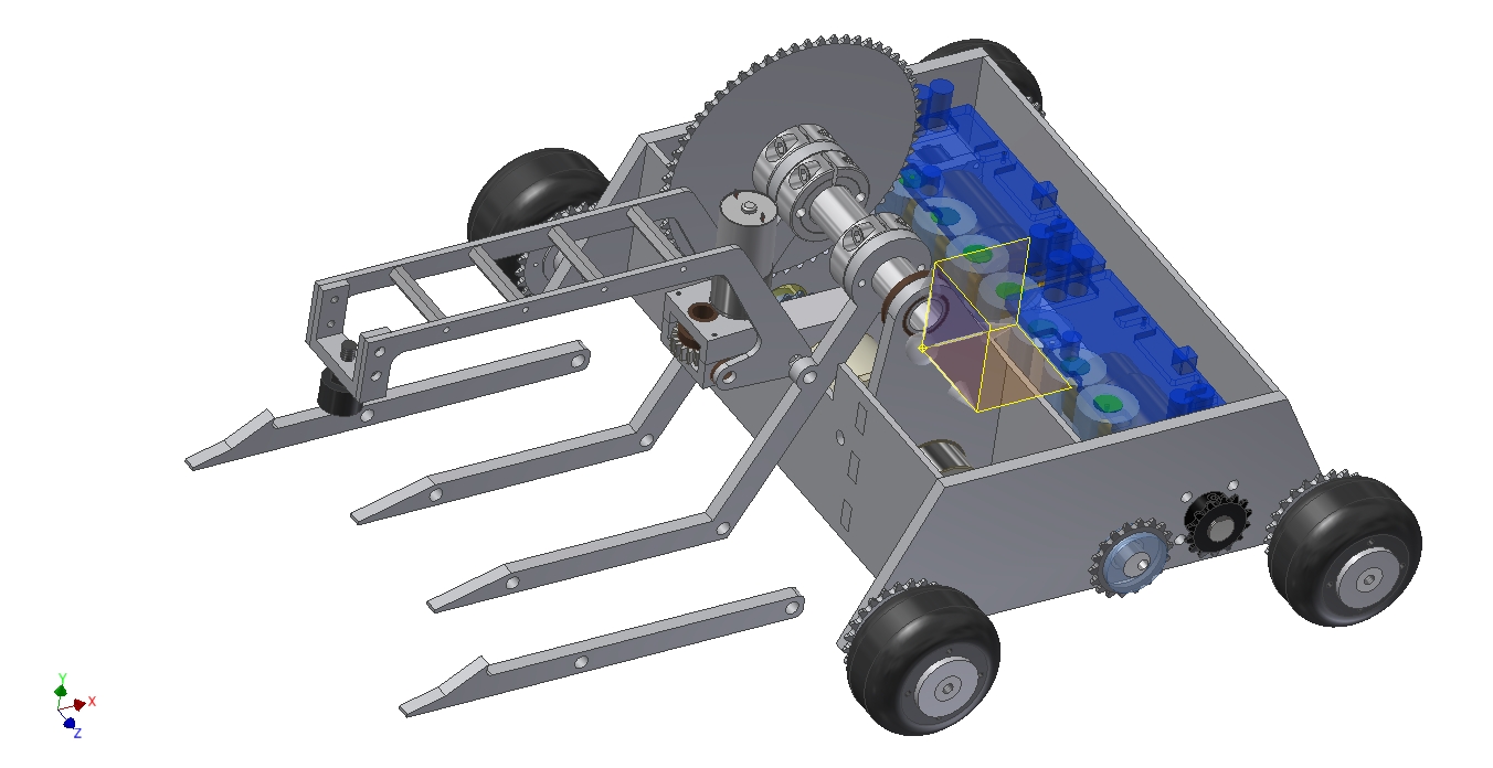
Cathedraling complete, and now with top and bottom covers mounted, including the huge obnoxious 12:00 cutout up top.
Why 12:00? Because it’s 12 o’clocker!
I really want to get a big EL panel kit and put it behind the cutout and have it blink 12:00 like an old VCR or broken alarm clock.
The weight as shown is 10.6 pounds. I’m now within the realm of possibility for making weight after factoring in the rest of the hardware.

The last detail I needed to address was the chain drive. The tensioner I imported straight from 30lb Clocker would work just fine, except the wheel placement would have caused the bottom run of the chain to hang like 1/4″ below the frame bottom! That’s just asking to get snagged on something and broken, leaving me stranded (again).
Not allowing that to happen. I rerouted the chain over two smaller roller tensioners such that for the most part the undercarriage is clear of chain runs. If weight allows, I’ll put a 1/8″ polycarbonate or other lightweight shield over this area to prevent accidental mishaps.

Here’s a better size comparison between 12 o’clocker, Überclocker Advance, and the 2008 version of Test Bot. So I guess 12 o’clocker isn’t really that big – TB was a full 12 x 12″, plus a few more inches of wedge and lifter arm.
Since the kart class caused my updates to run behind schedule a bit, I’ll put out a spoiler: The parts for 12 o’clocker have already been machined, and I can hopefully assemble most of the bot this weekend! Also on deck is a report on 30lb Clocker’s new clamp actuator, and more info on the D*C Robotics Track panels I intend to do this year.