I think I’ve formulated a reasonable list of next steps in order to solve my weird magic bootloader problem for Chibicopter, including trying different computers with the same hardware, messing with other USB-serial adapter settings, and learning how to logic analyzer in order to record the exact transmissions that are going into and coming out of my XBees. But right now, I just don’t want to see the damn thing (despite the demo season starting up again… uh oh). Fortunately, I have something mechanical and not software-involving to distract me, and that’s Chibikart!
Chibikart took its first few steps towards realization in the past few days, going from entirely CAD model to…

…oh boy. So let’s be clear: that steering wheel is ridiculously oversized and impractical. It was 10 bucks on the surplus channel, so I couldn’t resist throwing it in for kicks. Chibikart’s design is intended for a fairly normal 10″ wheel, and a 14″ one would result in leg clearance issues.
The seat, though, was what I was waiting on so I could more confidently finish the design. I didn’t know anything about the slope or layout of the bottom beforehand, and receiving it meant I could finally make its mounting bracket:

There’s 2 80/20 rails running under the seat and two little ‘crossbar’ type things which join them and also together form the bolt pattern on the bottom of the seat. It also conveniently shelters the battery. Not shown is the one-piece bottom plate, to be made from 1/8″ polycarbonate or similar. I’ve also taken the liberty of modeling up some 350W-type Jasontrollers. While the design shows four in the back, I’m probably going to locate two in the front to avoid running a few feet of extra motor wire that would not only add more resistance but also potentially mess with the sensorless position-detecting algorithms…if one exists inside Jasontroller at all. Long leads are just good to avoid overall, however.

I got the generic go-kart pedals in, so the first thing I proceeded to do was knock them apart to inspect just how shady they were. I noticed the pedal itself was a little…. wobbly. It turns out they are very shady indeed, but a degree of it which seems to let it retain full functionality. I guess that’s the hallmark of a well-engineered product? How incredibly cheap and shoddy you can make it without nobody noticing that it doesn’t work?!
That little arc segment magnet has a continuously varying radial field strength along its transverse (theta) dimension, so the linear hall effect sensor at the base will put out a varying voltage depending on how much you step on the pedal. The continously varying shitty glue joint gap, as it turns out, does not contribute much to said varying voltage. I legitimately thought the crazily positioned gap was the only thing generating the output voltage, but it doesn’t make physical sense for that to be the case.
Otherwise the pedal itself is somewhat underconstrained – it can wiggle side to side, but given that this changes the magnet’s position very little relative to the sensor, it is negligible. I’m surprised they even bothered with a tiny PCB to mount the sensor to.
Enough about pedals – how about some motors?

I picked four motors’ worth of parts “from stock” (scary I can say that, right?) and pitched them together. Now, the “stock” wasn’t perfect – remember that I sent off “my” fab drawings with these parts, meaning that the concept of allowance vs. tolerance was not distinguished. If I were to do it again (knowing now that mfg.com is legit), I would have more carefully specified dimensions such that I don’t have to, say, shave off 6 thousandths on a second operation on each endcap like I had to do. My total neglect of adding tolerances to 3-significant-figure dimensions means that using the accepted practice of 3-digits-means-0.005-deviation, my parts could have been 0.01″ out of whack. Clearly if these were actual mass production parts, someone would have lost an asston of money.
So for example, given that the can’s inner diameter is nominally 2.650″ and needs the endcap press-fit into it, a reasonable dimension to use would be 2.650 +0.001/-0.0005 for the can and 2.651 +/-0.0005 for the endcap. Notice the asymmetric deviations – the worst-case interference in this case would be 0.002″, and the other worst case only 0.0005. Yes, there are two worst cases – one too tight, and one too loose.

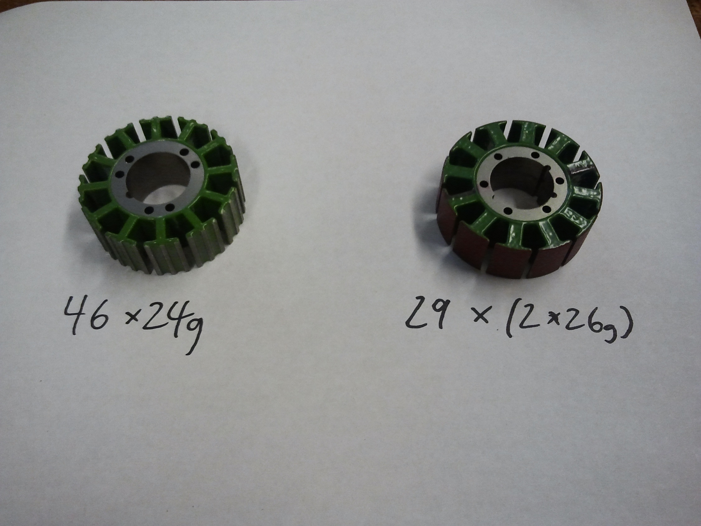
Remember how the other set of magnets in the other can was a perfect fit? The universe lined up for that one, but not for this set! The custom magnets I ordered were made to 0.003″ tolerance in each linear dimension. This means that they could have been 0.003″ too large or too small. The gap is about 0.026 or so, and therefore in this case it’s probably a combination of “slightly too small” and “can was machined with 0.005 allowable deviation in the diameter which resulted in a maximum circumference change of 0.015”.
This is part of the reason why I will move away from whole-circle magnets, actually. If I can’t be guaranteed a perfect closed circle every time, it’s not really worth bothering with. An installation jig wouldn’t take that much more time, and could deal more easily with slight magnet size variations.
Something like half of all mechanical engineering is based on consistently manufacturing parts/products to minimize deviations and rejection/failure rates, and designing systems which can handle manufacturing variations. The takeaway lesson is that making things on a large scale totally sucks ass. I’m not going to be making 3.6 million of these per day any time soon, but if I’m having this much fun with just 4, then there is clearly room for improvement!
And don’t even get me started on the miserable failure of a bearing fit the endcaps all exhibit. Oops.
And now, a change of pace:

Look at the nice thing! I made myself a miniature Hobbykinging rig using laser-cut acrylic. I hereby christen this the “REEL DEAL”.
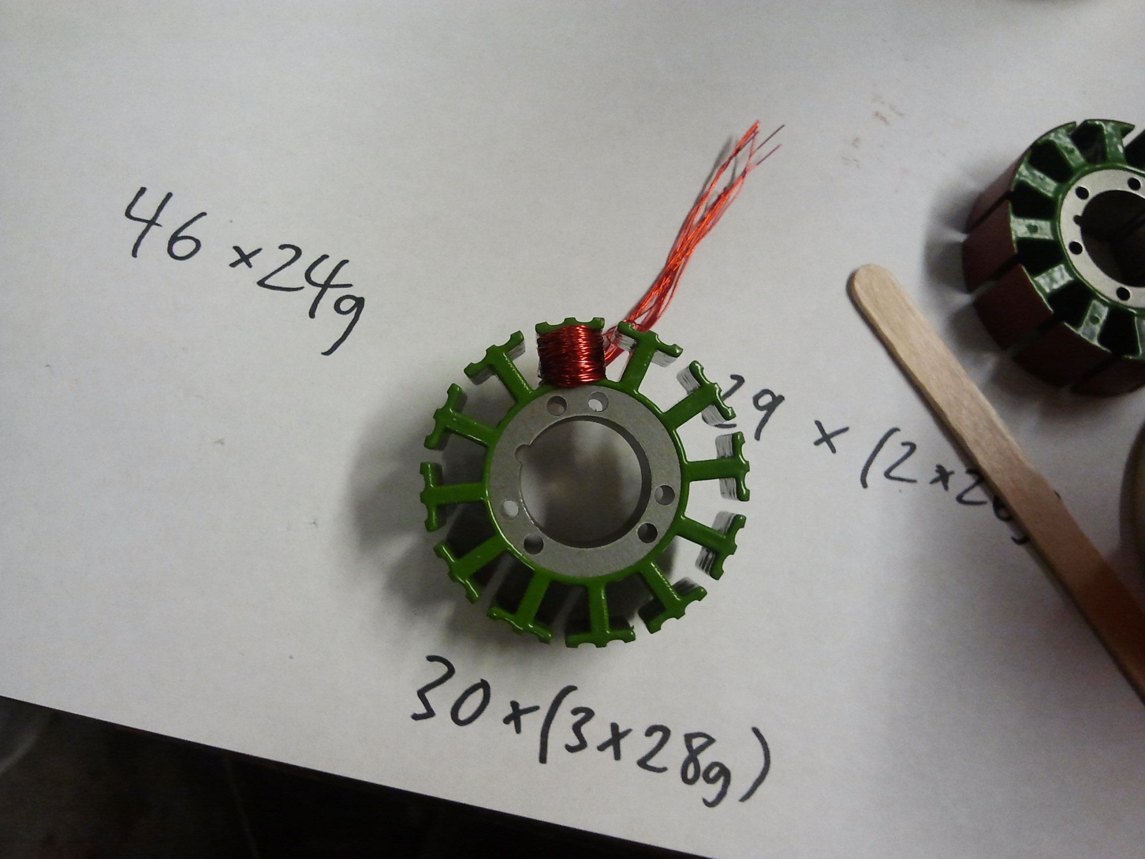
The Reel Deal holds six (or up to 9 in this version) little magnet wire spools from which a string of parallel wire emerges for me to wind the stators with. Some zip ties sandwiched between the black frame and the reels adds a bit of tensioning friction. There wasn’t that much friction, though, so I’m still having a bit of fun with occasionally losing a wire off the side – as the reel is used up, this will become less of an issue.

We now move on to a picture more typical of one of my build updates: infinite waterjet! I think this might actually be the first (possibly second) time I’ve waterjetted something this entire semester. What the hell? Aren’t I supposed to do this every other day?
This batch of parts was made from the pile of metal plate that was going to become Super Make-a-Bot before that project was (effectively) abandoned. There were a multitude of reasons for the death of sMAB, one of which was the lack of any real innovation above the field to justify it being really fucking expensive. I estimate that I dumped about $500 into the project and still had to go $5-600 more, for something which isn’t much better than a Replicator (which my research group bought one of recently anyway – more on that when it gets here!).

I executed one of my tightest packings ever on that plate, mostly because I only had one. This was not done in one shot like I usually do, though. My usual procedure of manually routing each part in sequence takes about an hour or so of just staring at OMAX Layout while clicking buttons. This time, I tried the “other” way of routing one part and then nesting them through OMAX Make, right before I fire it off. This worked pretty well a few times (check the 8-piece array of corner trusses), but then things started going wrong.
Almost inexplicably, I started having head-dragging problems, where the machine would mysteriously carry the whole plate, fixture weights and all, an inch or so, destroying the part coordinate system and ruining that area of the stock. I couldn’t locate the source of the problem at first – it’s usually caused by a part or scrap floating up and catching the nozzle as it traverses, but I had all things which could float tabbed in (Hint: “Create Tab” is awesome). Through frustrating recuts and space hunting, I discovered:
- The aluminum started warping. This plate must have had asymmetric residual stresses from rolling or something, but after the first few parts came off, the whole thing was bending up almost an eighth inch from corner to corner. I’ve actually not encountered this before. This might have caused some head bumping problems, but not as much as…
- …1:1 aspect ratio hole centers. By this, i mean the little donut-hole left over when the machine finishes cutting a circle. If its cross-section diagonal is about the same as the ID of the finished hole, then it could turn sideways and stick up from the surface of the part as the machine blasts the last bit of connecting material away. I only discovered this after picking up a scrapped part and finding such a sideways hole plug sticking up with a huge gouge mark from the head. This is also something which, oddly enough, I have not experienced before.
I’m going to write alot of this off to forgetting little details of machine operation from not doing it in a while, but the end result is that after the next few part sets, I was down to cutting one-by-one in any possible space which would host the part.

After cleanup.
So this plate is actually 5052 alloy, more commonly found on boats and truck-mounted tool boxes than machine parts, but I bought it for sMAB because it was cheaper than 6061 and 3d printers really don’t need that much beef (it’s about 75% as strong as 6061). The perk to it, though, is that it’s shiiiiiiiiiiiiiny. I’m not sure if it’s just a polished finish or if it actually has a pure aluminum (“Alclad”) coating, but damn is it shiny. Looks way better than the typical streaky mill finish of 6061.
The good news is that all the tabs and slots fit (Yes! Haven’t lost that skill yet…). The bad news is that I inch ever closer to having to finally wind all four of those motors…

That’s it for now! I’ve also prepared the shafts for the motors, which also needed a little bit of material shaved off for a reasonably tight but slideable fit. This whole ‘real manufacturing’ thing sucks. Hmph. I was almost better off making the four motor cases from scratch this time.
I’m working on a system for mechanical braking which reuses the fender brakes from standard Razor A scooters. This will be put on the back wheels so I have a backup when the Jasontrollers’ regenerative braking fai….. wait, they don’t have any, that’s right!
Next: Cutting 80/20!