When we last left rEVolution, I was halfway through the process of turning my hands into bloody, tattered stumps. It’s a ritual that occurs with the construction of every hub motor (which means I went through it four times to make the RazErBlades).
And by all that I mean winding the motor. Here’s the end result, terminated for presentation.

I ended up keeping the “split dLRK” winding style – making 6 teeth wound AabBCc and the other 6 aABbcC. They’re terminated in separate non-connected star points on the underside. The leads are grouped by their respective phases – motor 1 is the classic white-red-black, and motor 2 gets yellow-green-brown.
My patience deterioration is very clearly shown in the picture. I wound this motor starting from the Aa side and proceeded counterclockwise. You can see a decay in the quality of windings and the neatness of layers right after the aA phase on the left. Then by the last one, it’s all gone to hell.

To maintain engineering rigor, I took measurements of the DC resistance of each phase. This will pretty much determine how much current the motor can ever pull.
I proceeded to defenestrate engineering rigor (MITERS has very large ceiling-height windows, so this was easy) by scribbling the resistances hastily on the workbench. In dry-erase.
From the picture, you can deduce that the C phase of motor #2 is about 10% short of turns. Yeah, I think I pretty much stopped caring by that point. The other phases should have 39 to 42 TPT, but I’m guessing 35 or less made it onto the last C phase if I’m lucky.

Fit test!
I tried giving the motor a test spin using a sensorless controller (essentially by bootstrapping off Melon-scooter), but neither half-motor exited the “starting” regime. This was concerning. Did I terminate them wrong? Wind something backwards just a little bit?
A few minutes of diagnosis revealed that the motor was technically running smoothly, but the controller just didn’t increase throttle. Applying voltage to each half-motor in each combination of the 3 leads (i.e. A to B, A to C, B to C…) produced 6 identically spaced angular positions each time – which is indicative of correct winding, since that’s pretty much what your controller does anyway, just alot faster and without colliding alligator clips.
I pretty much just declared it to be a fault of shitty sensorless aircraft controllers being unable to deal with inertial loads or high friction systems.
Without a supply of hall sensors, I put the frame and motor away and started thinking about the other parts of the electrical system.

EVs generally have 3 big components – motor, controller, and battery. With the latter two, you can shoehorn anything in as a motor. With motor and battery, you can be a dumbass like me and control the vehicle with a mildly more civilized form of touching 2 wires together. But without a battery, what am I to do – run the whole thing from a bag of lemons?
Luckily for me, people have figured out how to stuff the equivalent of tanker-loads of lemons into lithium nanophosphate cells. Above is the 12S2P A123 DeWalt 36v Lithium pack during mid-assembly.
I managed to find some terrifyingly wide copper braid this time, and I think the cells just look so much better with them instead of the \m/etalpaxxx‘ quadruple braid. The massive interconnects just scream this pack will dump enough amps to destroy you and everything you ever loved.

Another serving of giga-braid later and the pack structure is complete. I decided to split the pack into 2 6S packs again for balancing purposes, but this time the pack isn’t two separate entities. Shane supplied me with Real Legit JST-XH Connectors of Battery Balancing (+14, for pin count), or otherwise I would have probably resorted to 7 pin-header again.

Bottleshrink returns once again, but this pack is so long that I needed the midsections of 3 bottles to completely enclose it. Luckily, it fit 2 liter bottles fine, and I just pulled a few out of the recycling bin.

A quick check of the cell levels revealed that these cells are in fact still quite healthy despite sitting for an unknown period of time.
Of course, that all went to hell on the first charge, and I had to spend an hour manually bringing each cell group up to full.
back to motters
Given that the motor itself seems to be correctly wound, I surmised that all my problems would go away as soon as I added the requisite hall sensors to the slots.

And here they are, temporarily CA’d in place as a soldering fixture. LRK-style motors need a physical 120 degree sensor arrangement, but I’ve always found cross-stator wiring work to be awkward. Therefore, like on the skatemotors, I take the B sensor and flip it around for a 60 degree, every-two-slots layout.

I secured a chunk of 6 pin cable to the access slot in the shaft using epoxy. At the same time, I elected to secure the phase leads to the other side of the motor. The whole epoxy-globbed mess was then introduced to my epoxy curing oven fixture implement hair dryer hanging by its power cord from the ceiling.

After the first round of epoxy set, I finished connecting the sensor wires. Unfortunately, I managed to break off the output pin of the B sensor… and so ended up having to install the opposite one anyway.
Luckily, this design left plenty of space near the edge of the stator, so running the wiring all the way around the motor wasn’t as difficult.

The sensors got their own layer of goop. I kept finding buckets of different epoxy fillers around MITERS – this is “cellulose” filler, which probably just means paper dust.
It claimed to be less cancer-inducing than either the silica or phenolic microspheres, so I gave it a shot.

After another hour or two of watching glue dry, I put the motor together. Here it is – Dual (Non-)Interleaved RazErMotor!
But does it work?

That’s a gooooooooood question.
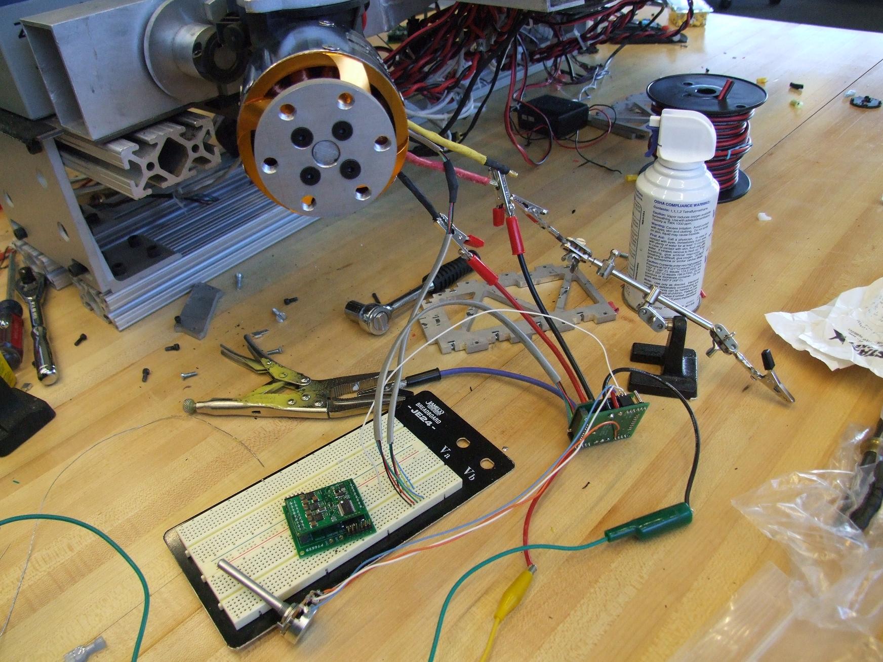
Using the Kelly KBS which sort of miserably failed at running Melon-scooter, I was able to briefly power up and spin the DNIR to full speed. Qualitative observation tells me that at least I didn’t get it that wrong. The fact that it moved at all meant that I got the sensor arrangement correct for the “split dLRK”. Now, for this test, I just paralleled the equivalent phases of each half-motor. Once I put together the RazerDEC board, each motor will be powered by its own controller, but triggered from the same sensors.
The speed was visually in the “correct” range and it started and ran smoothly with no signs of improper winding or termination.
that is, until it started sounding like a moped.
Oscilloscope diagnosis of the sensor outputs showed that every mechanical revolution, all 3 sensors were blanking. This caused confusion for the controller for a split second until the sensors outputted a valid signal again.
Well, this is disappointing. The sensors – which, mind you, I had JUST encased permanently in a cellulose-epoxy matrix – seem to be having power issues once per mechanical revolution. I’m fairly certain it’s power, anyway, because there is no physical way for all 3 sensors to read the same field orientation the way they are set up.
This actually means it shouldn’t be hard to fix – my guess is that somewhere, a bare solder joint is nicking the metal can once per revolution and causing a short between sensor 5 volts and ground. A further test to confirm (or dispel) this would be to look for dips in the 5 volt line during each revolution.
In the mean time, there’s no pics of it running, therefore it didn’t happen.