Since 2002, Dragon*Con in Atlanta has been my principal bot-party every year. The Robot Battles competition has been held there every year since 1991. That makes it one of the oldest combat events around. My first competition year was 2003, and I also went in ’04, ’05, and ’06.
In 2007, other matters forced me to miss the event. Fortunately, in 2008, I am no longer a miserable froshling, and may come and go as I please. This is good. It allows me to return to my fan club, which no doubt has gotten a bit stale from waiting around for two years.
Hehe, fan club. Funny.
Anyways, regardless of the circumstances, I need to make an epic comeback in 2008. I need to kick ass in an epic fashion. So, I need an epic robot. Announcing what will hopefully be my first 30lber build for the Robot Battles competition as well as the NERC/RFL Sportsman’s Class:

Cheesy shoop’d logo included in price of admission. The design incorporates the Doomsday Clock as part of the text, with the minute hand cleverly reflected one minute past midnight. Symbolizing doom… or something. Anyways, onto the bot.
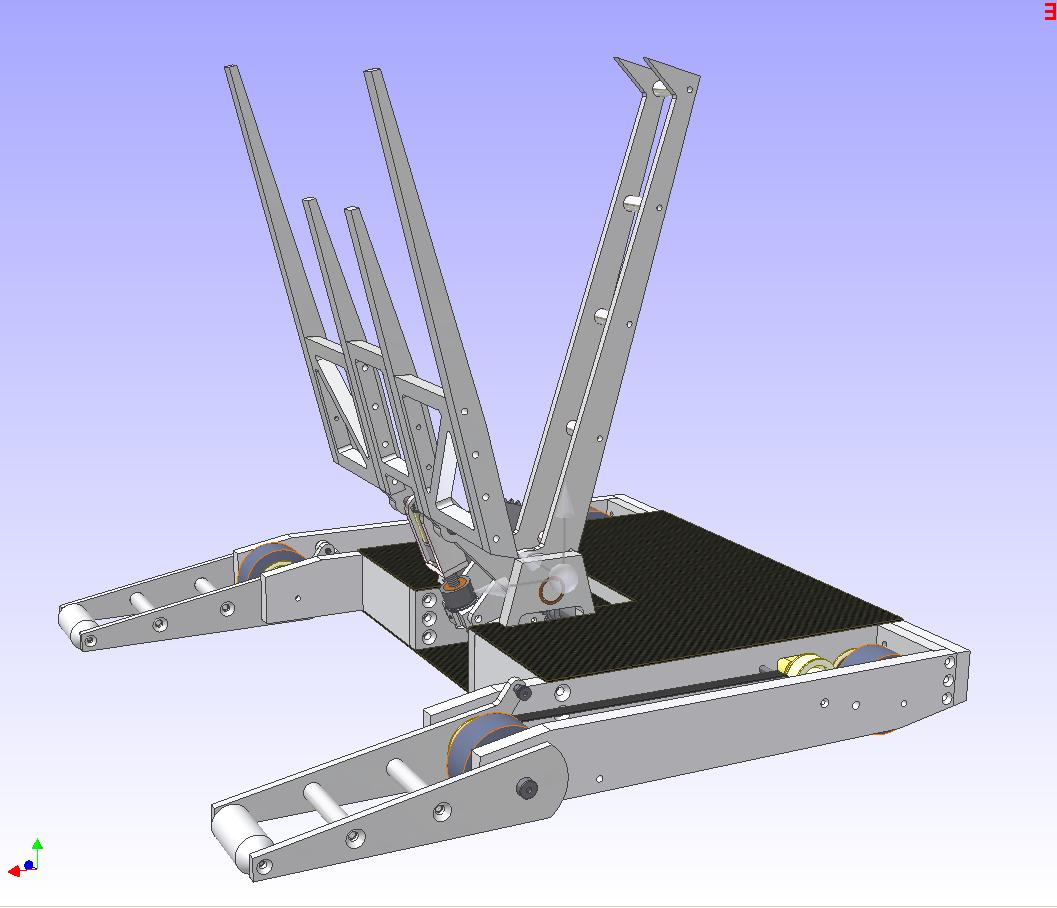
The most prominent feature is, of course, the giant fr0k. I have neither seen nor heard of a clampbot-type design, which a two-part lifting mechanism can entrap the opponent and lift it completely off the arena surface, used at Robot Battles. This is quite strange – the arena surface in question here is an open stage, and if you go over the edge, you lose the round. It seems control-type robots would dominate. But D*C has seen its vast majority of entries fall under the hammer, wedge, plain lifter, flipper, and ramming box-with-pointy-things categories.
Perhaps I’ll set off a bad trend, but at least it’s more interesting than the current spinner-vs-armored-box debacle in the RFL.
So, Ãœberclocker will be a clampbot, with a few kicks thrown in. The main difference I observe compared to other clampbots in various weight classes is the set of idler rollers up front. They are spring-loaded to the floor in normal operation. When the bot has an opponent in the fork and raises it off the ground, its center of gravity will shift to forward, causing the bot to balance on the idler roller arm and the front wheels (the rear wheels being raised off the ground). If I lift the opponent higher, the center of gravity will fall back over all 4 wheels, and normal operation can proceed.

This two-wheeled intermediate, semi-stable condition is what I hope to extract a little fun from. I hope to be able to whirl the bot doublet around at a high rotational speed, then release the clamping force suddenly. This should pitch the opponent a decent distance horizontally. Hopefully right off the stage.
That is not the main strategy, of course, but it’s something to include. I hope it works.
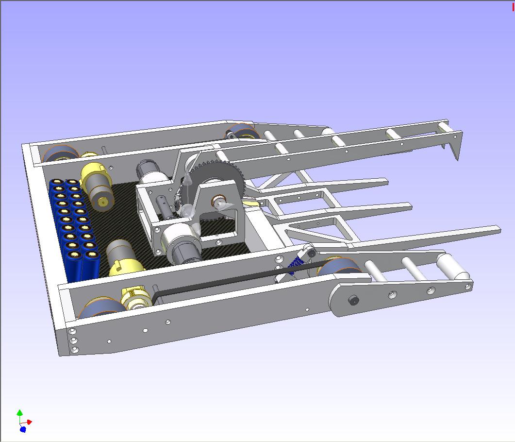
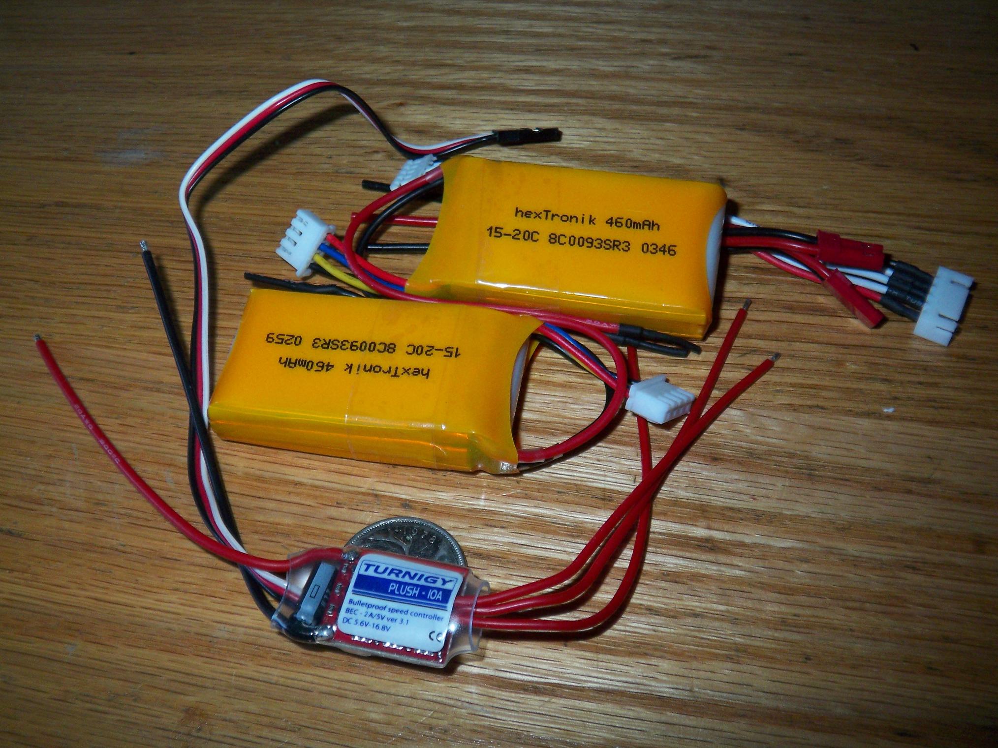
Slightly obsolete drawing, but the basics have not changed. The drive motors will be 18 volt drill units similar to the ones I used to use on Test Bot (before I started choppin’ and screwin’ them). They will indirectly drive all four wheels, since the geometry of the frame makes direct drive impossible. Heavy stuff, of course, is in the back. I might actually stay with giant nickel-chemistry cells since they are great for ballasting….and lithium batteries of this size is going to cost as much as the rest of the bot.
The lifter motor will be a fun work of engineering. I couldn’t find any single motor and gearbox on the commercial channel (within reason) that had the torque necessary to lift and hold a 30lb opponent AND fit in the bot design. The Banebots CIM gearboxen were a good choice, but were too long and wide for the design, and with the motor, would weigh in at 8 pounds. That is not acceptable in a 30 pound robot.
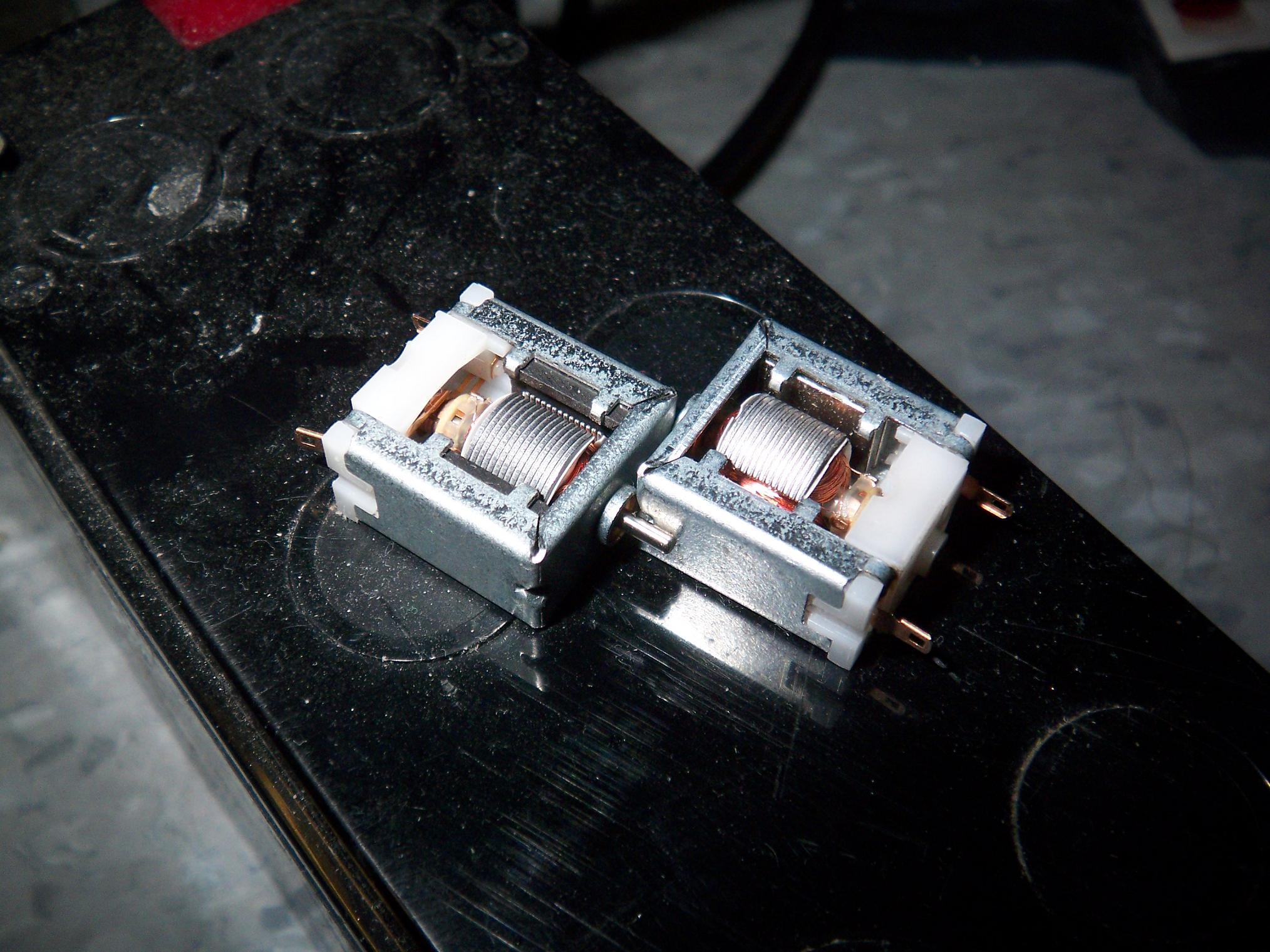
So then plan is, as I termed it, to “ghettofrankenb0x” two more 18 volt drill motors. This involves adding another 6:1 drill gearbox stage on top of the 36:1 stock gearbox, all in a custom housing. Each motor is then reduced 216:1. Two of these are coupled together at the output shaft and then mated to an additional 3:1 chain drive to the lifter axle.
The output speed should result in the lifter swinging (no load) at 120 degrees of rotation per second. 120 degrees is roughly the maximum swing it has, and 1 second is *PLENTY* fast for a lifter like this. This dual motor 400+:1 reduction will have enough torque to dead lift 150 pounds, but I designed it to lift and hold a 60 pound robot at the end of the arm with the motors under power to fight backdrive. So a 30lber should actually be quite trivial.
But the drill gearboxen now suffer from “Banebots Syndrome”, which is the stacking of too many reduction stages with no increase in gear size or width. Chances are, they will not stand a dead stall. However, the point is to not dead-stall them against something solid.
Here’s the gist of it.
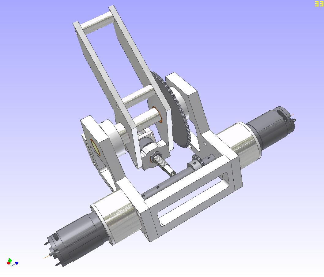
An all-aluminum structure supports both the lifting forks and the clamping arm. The dual ghettofrankenb0x is seen here. A small gearmotor, mounted to a leadscrew assembly, will drive the clamping arm. I currently have a B62 motor that was designed in for this job, but may switch to something of a similar form factor if it proves not up to the task.
The pivot point for the clamping arm is actually mounted in a floating assembly with the leadscrew nut. A series of disc springs hold the two apart. This is a measure to save the motor against hitting a suddenly dead stop in the form of either travel limit or another robot’s top. It also adds in a bit of “preload” to the clamping arm when it bites down on an opponent. This is not designed to save the system if the opponent tries to force its way out – a real indirect drive will make no difference in that case.
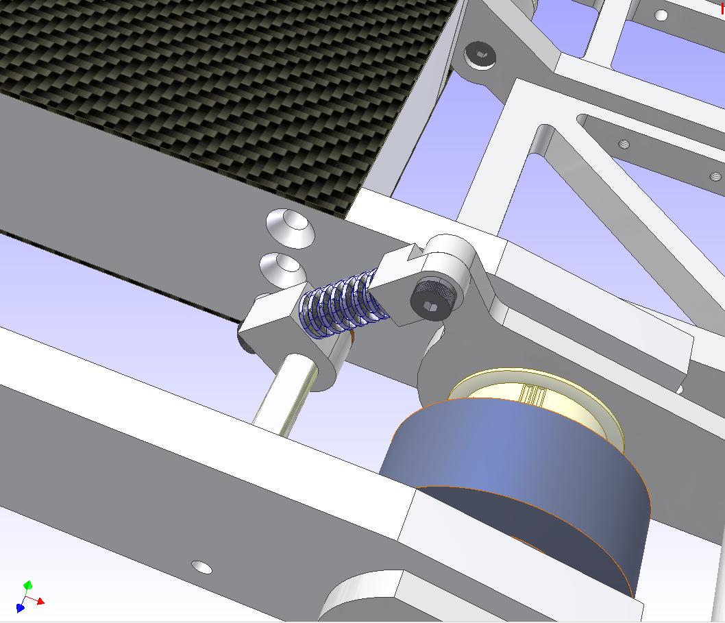
Here’s the spring-loading device for the front support legs. I could have avoided this bit of complexity with a large torsion spring or two, but had trouble locating suitable springs. Torsion springs are supposed to act over a wide range of motion. I only need about 10 degrees of springiness or so, which means a torsion spring will make very little difference unless it’s been massively preloaded. Torsion springs of the size needed to balance the robot were also quite huge to begin with.
So a “shock absorber” type setup was implemented instead. This is just a die spring from McMaster riding on a shoulder screw, which is in a movable mount attached to a drive pod standoff. It should allow the legs to move over small obstacles like the “floor bar” hazards. This is also the travel limiter for the front legs (such that the robot can only tilt forward about 10 degrees) since the spring won’t compress further than its solid length.
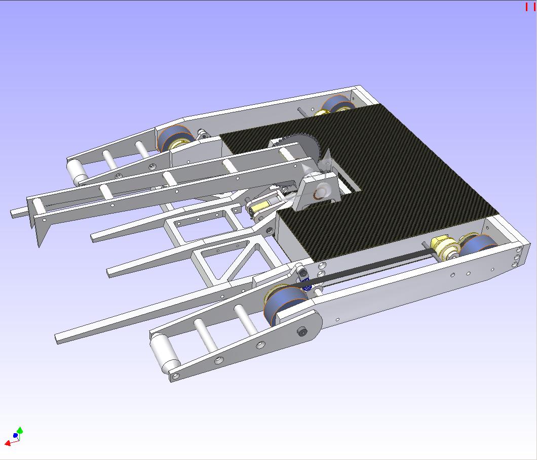
External overhead view. The robot is 20 inches wide and 16 inches long at the end of the chassis. The support legs take it to 22 inches long, and the tip of the fork makes the whole robot 27 inches long. This is huge. The chassis size is very reasonable for a 30lber, though. The height of the frame is 2 inches, and the height at the fork is 5.5 inches.
Top estimated speed of the thing should range between 10 and 12 feet per second. This is very zippy, and I might scale back a bit. However, fast is good for chasing down and grabbing opponents by the collar, and then whirling them around.
How many robots can I throw into the crowd?*
Building this bot will be a test of my machining skills for sure. Since the frame has many 2D flat plates, most of it can actually be pre-fabbed on the waterjet machine. For instance, this is a test layout of all the 1/2″ aluminum parts on a slab of 1/2″ x 12″ x 28″ 2024 aluminum I bought a while back for TB.
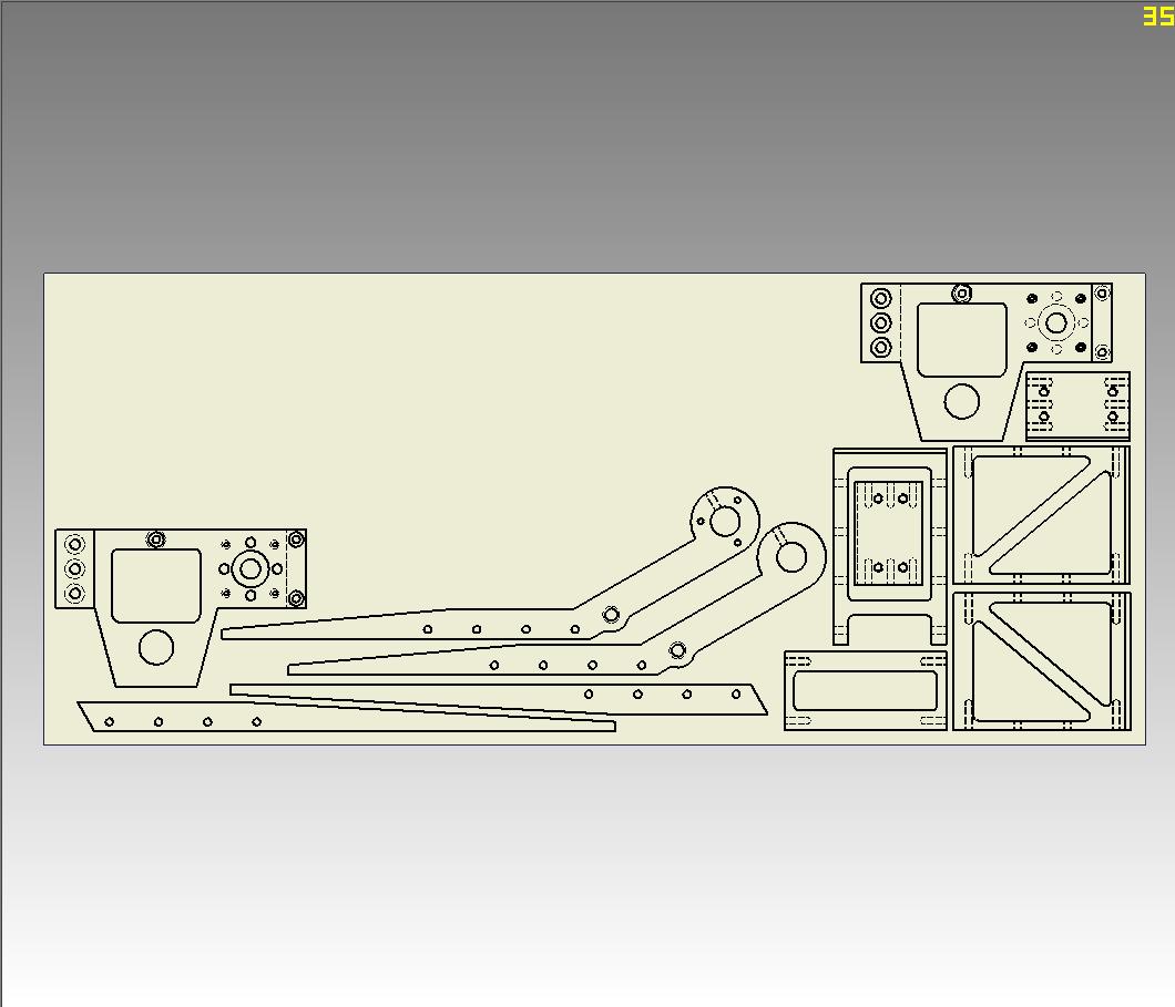
Most of the manual machining will be on the UHMW frame parts (since UHMW waterjets like total shit) and the drivetrain. In other words, pretty standard stuff. All I need is, of course, the time and machinery, both of which are in plentiful supply over the summer.
I also intend to make a closed-loop control for the main lifter arm. I am not going to jiggle both transmitter sticks in perfect synchrony as to clamp, lift, and drive at once. I have yet to find a way to shoehorn in a servo feedback device onto the leadscrew assembly for the clamping arm – perhaps a linear potentiometer or something.
So this is the official unveil of the concept. Staring the week after finals (this week), I should have three months and a week to get this thing done and tested. Can I do it?
Only time money will tell.
*The answer to this is ZERO. The crowd is at least 25 feet away from the stage. Robot Battles also has a spotless safety record because it holds common sense to be the baseline rule. Let’s keep it this way, folks.