The January Bot: Project Cold Arbor

Since the beginning of televised robotic sports history, combat robot builders have been repeatedly asked by fans, enthusiastic onlookers, and bright-eyed newbies, a variant of the following question:

D00D WHY DON’T YOU PUT LIKE A BUZZSAW OR SOMETHING ON YOURE ROBBOT SO YOU CAN LIKE CUT RIGHT THRU THE OTHER GUY AND SHIAT????

Good question. Why haven’t we? Sawbots are conspicuously missing from the combat robot hall of fame. Everybody wants to see them, but there have been comparatively few saw weapons built in all of the history of robot combat, and even fewer ones which actually achieved its end goals. Minion, the most famous saw-wielding Battlebot, replaced that weapon with a kinetic energy disk starting in Season 3.

So why is this the case? Saws need a delicate balance of torque and speed actually cut something. Too much of one or the other, and you either blunt off the teeth or jam it in the opponent. Essentially all saw weapons to date have been directly driven or geared very fast from a (comparatively) low-torque electric motor. That means they can scrape and spark nicely, but actually laying into an opponent will stall the blade.

The other element missing is controllable pressure. It’s difficult to cut consistently in the same place on something that’s flailing around or moving. A saw that sticks out the front of a robot but is otherwise fixed has no control over how quickly it can advance teeth through opposition armor. If it’s simply jammed into the opponent, then the torque required to actually crank the blade teeth through the material becomes phenomenal. Most saw weapons extant today rely on the stored kinetic energy in the saw to deal out damage.

This particular aspect was what inspired me to think about the Sawbot Conundrum when I was watching old episodes of Robot Wars featuring the house robot Dead Metal. Observe how effective the saw is on Dead Metal from the 2 minute mark onwards here. Dead Metal works because it is able to trap the smaller robot in its pincer jaws so they can’t move. The saw also advances on a linkage at a modest pace and has plenty of horsepower to back it up. It can actually cut things.

I immediately wondered if I could replicate the function in a smaller class, say, 30 pounds. Control of the opponent is the dominant trait of Überclocker, but it doesn’t really have a means of doing… well, anything else. I wanted a complementary Überclocker which trades off some of the control for more ownage.
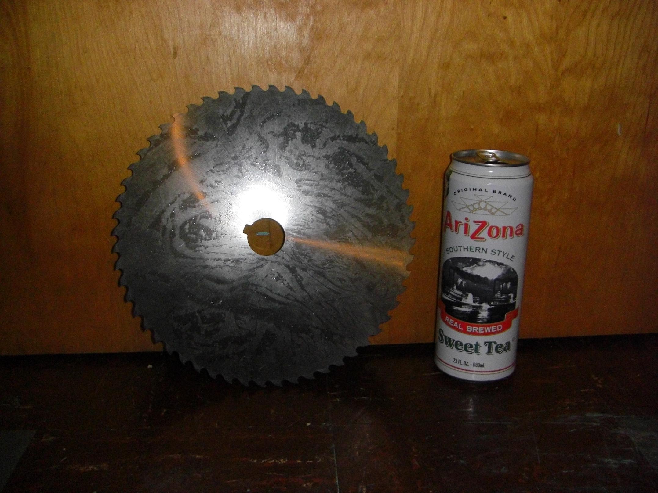
In an alignment of mechanical planets, I was swiping some more slitting saws for MITERS off Ebay when this mutant blade showed up in the listings. I didn’t even know they made “slitting saws” this large. It’s a 10 inch blade, 3/16″ thick, and weighs a solid 4 pounds. The bore is 1.25″ and keyed.

Now I was practically obligated to build a robot around it.

To drive a saw this large would require immense torque. I investigated planetary and spur gear reductions before deciding that neither could satisfy the torque transmission requirement, be minimal in weight (spur gears were totally outclassed here) and also be easy to build or cheap to buy (there go all planetary gearboxes in existence).

Luckily, I remembered that I had…
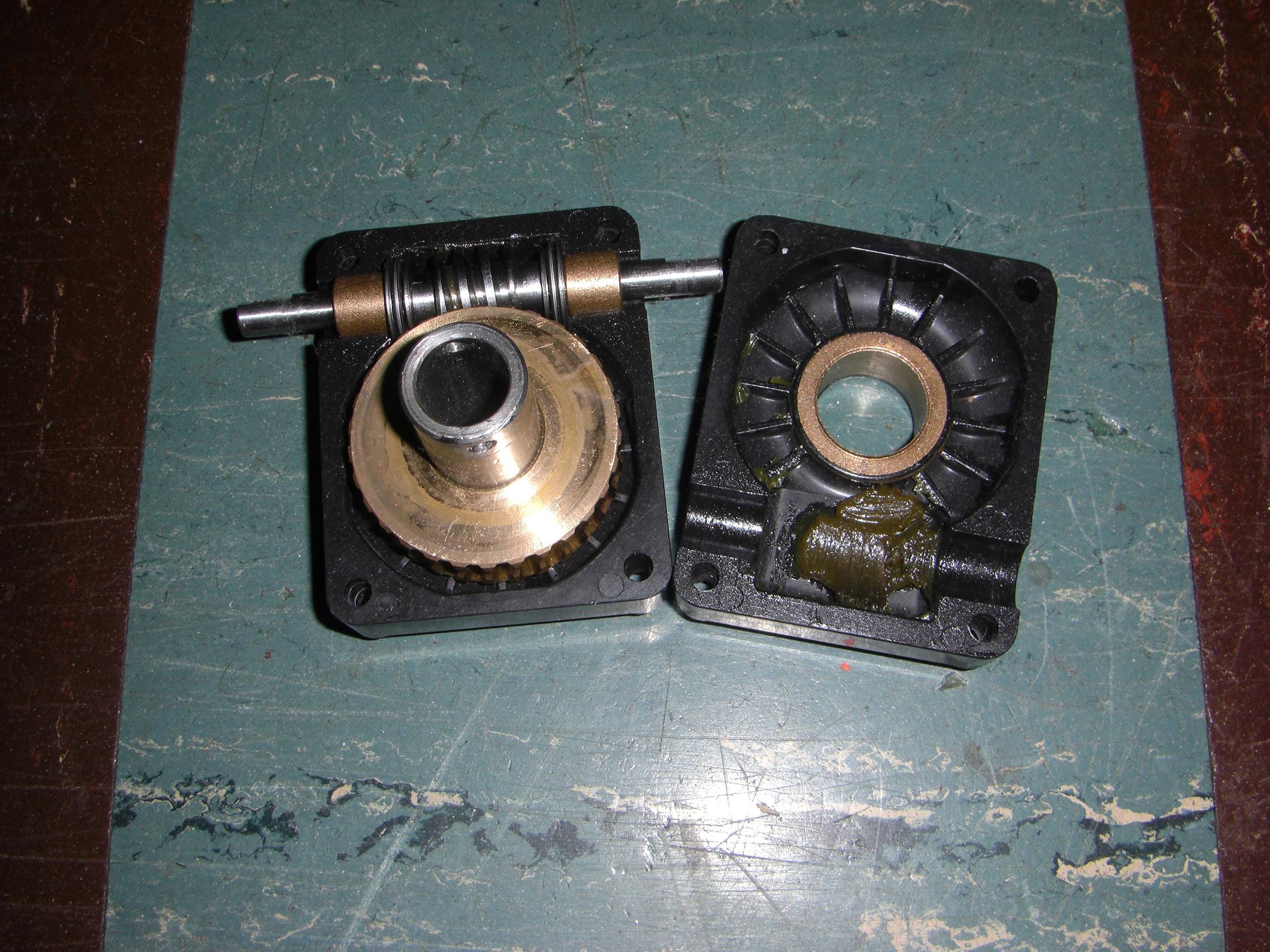
…this worm gearbox that I scrounged out of a pile of discarded lab cleanup materials. It came of the base of a nicely waterjetted and assembled robot arm that looks like something heavy ran into it – or, more likely, it ran into something heavy. Either way – free 30:1, 12 (ish?) pitch single-enveloping worm gear.

While worm gears are notoriously inefficient, it’s much easier (in today’s world of brushless one-upsmanship) to dramatically over-motor a weapon to compensate for that. Worm gearboxes are probably the most common things in industry, also, because of their simplicity, compactness, and durability. If you don’t mind the less-than-peak efficiency – which \m/assive \m/etal generally doesn’t – then why bother with something else?

There do exist machine tools which use worm gear driven circular saw blades to cut metal, generally competing with bandsaws in situations where edge finish and accuracy are important.

They are known as cold saws, named for the fact that they use a toothed steel blade to generate chips of material instead of a disc of abrasive rotating at high speeds. I like them better than bandsaws, because I can hang off the handle on the largest cold saw in the shops and take down a 4″ solid round of steel in under 30 seconds, and that’s just too awesome.

Thus the inspiration for Cold Arbor was complete. The name is both a play on cold saw and the Battle of Cold Harbor, one of the “bloodiest, most lopsided battles” of the American Civil War.

Anyways, I love my found object gearset, but that janky plastic case has to go. Why put such nice gears in a plastic case?

Oh, right – nobody is expecting me to hang a 10 inch sawblade off one. Using the existing mounting dimensions, I designed this preliminary gearbox case, to be made of aluminum. Some 7/8″ bore ball bearings will take the place of the bronze bushings. Since the shaft is hollow, a large bolt running through the center makes for easy blade mounting.
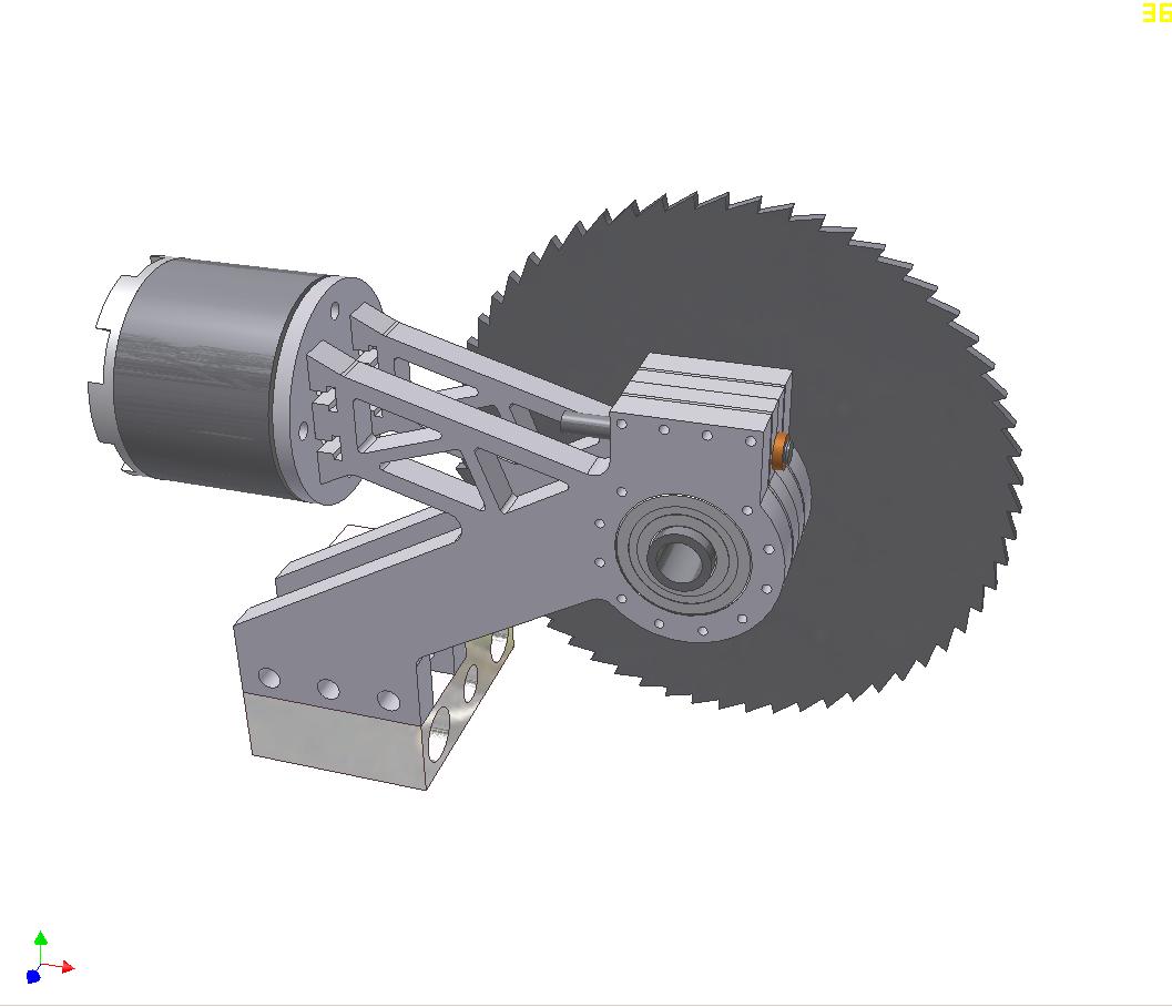
So here’s the first try at the actual blade assembly. This is more inspired by a sliding compound miter saw. The premise here is to reach the blade as far into an opponent as possible. Using a plain swinging saw, the maximum “cut depth”, so to speak, is limited to the saw radius minus the radius of the gearbox. This design was an attempt to remedy that by allowing the saw to “reach” further by sliding.
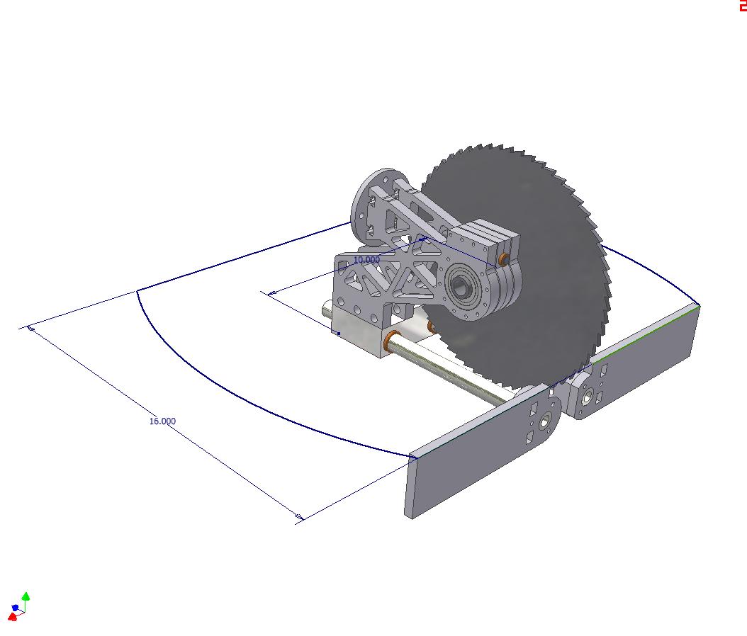
The prelim design more progressed, showing the prospective linear bearing rails. This was about as far as the design ever got before I realized it was going to weigh far too much, and would suffer from stiffness issues. So that was scrapped.

The truncated circle floorplan begins to make a return here.
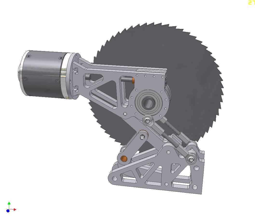
Crazy design number 2 uses a six bar(!) linkage that allows the saw to retract fully into the footprint of the robot, but extend about 6 inches forward. The swinging motion bring the saw over, then down upon the opponent. The whole thing would be moved by 1 actuator, mounted at the bronze bushing and causing that part of the linkage to move about 70 degrees.  The motor would remain parallel to the ground at all time.

A much more practical idea than the sliding design, but ultimately, it also faced some pretty hefty weight issues, especially after I designed in the actuator.
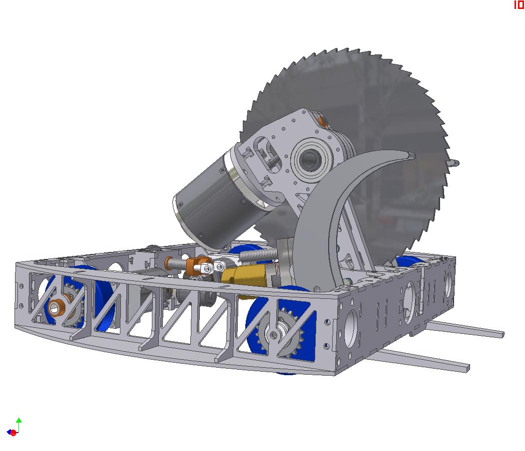
Alright, big leap of faith here. What the crunk is going on?

I decided to give up on a cool swinging linkage and just made  a conventional linear actuated pivoting assembly. This linkage swings through just over 75 degrees of motion to bring the saw all the way to the ground in front of the robot.

The motor mount is integrated into the body of the gearbox to make it easy.

One additional component visible here is the actuator for the clamp. Both clamps are connected to the single linear actuator at the rear, so they should move (sort of) together. They are linked to the actuator nut with a ball-jointed tie rod.
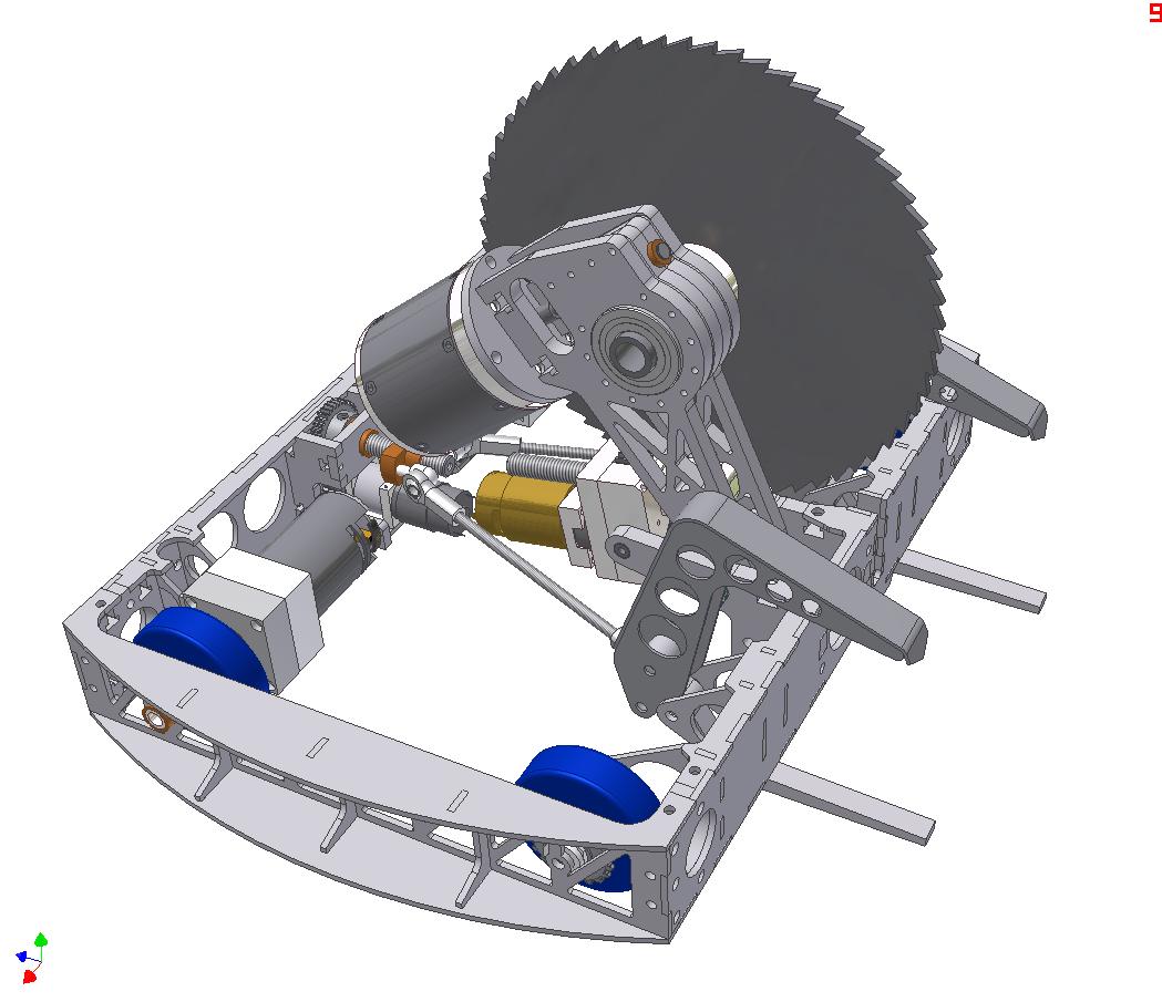
A clearer shot of the clamp actuation. Notice the top claws have been replaced with a fancy to-be-welded structure.

While the claws actuate together, both clamps (top and bottom of each side) are capable of independent swinging motion. This should allow me a bit more flexibility in approaching opponents.
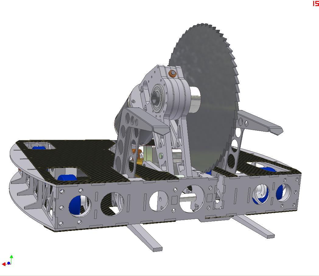
A bit more progressed now. Top and bottom cover plates will be the usual order of 1/16″ Garolite reinforced in select locations.
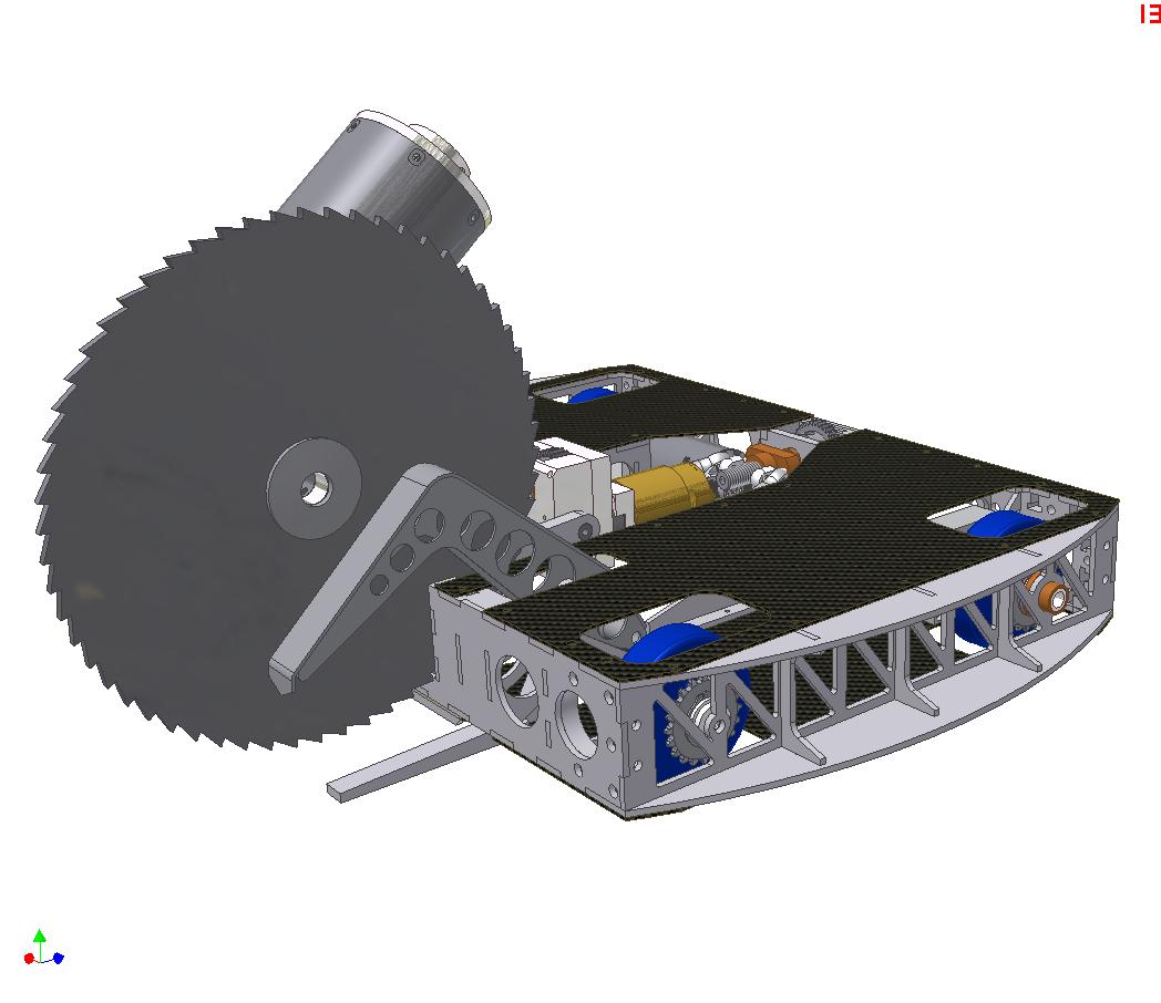
The saw in full deployed position. The bot can actually reach far enough to cut itself. To prevent this from happening, the leadscrew length in the actuator will be tuned appropriately.
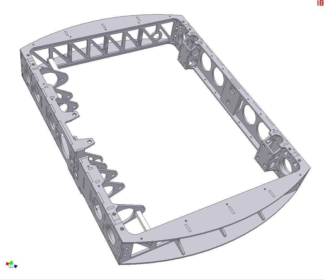
The frame of the bot will be sort of a unique first try for me. It will either be zinc-aluminum brazed or, with luck, be legitimately TIG welded. Either way, my first foray into “permanent joinery”, so to speak. We’ll see how it turns out. The robot just didn’t have the space to put T-nuts int the frame.

The frame is four pieces – front, back, and the two sides.

Filling out the internals a bit using AUTODESK INVENTOR 2010!!!! on my NEW LAPTOP!!!!. The fancy welded flaw is gone – I figured four fancy welded assemblies were enough for a first shot. They have been replaced by a single flat aluminum top claw. Less rigid, but also easier to make and assemble.

I plan to let this bot use the same batteries as Überclocker, since I already have packs made. 7S A123 cells yields about 23 volts nominal and 25 volts peak, which is roughly the tolerance level of the Victor 883 controllers anyway. I have leftover 883s and 884s from Clocker.

Electronics will be mounted on “cards” in the body. Not really for quick access and removal, but there wasn’t a way to mount everything horizontally.
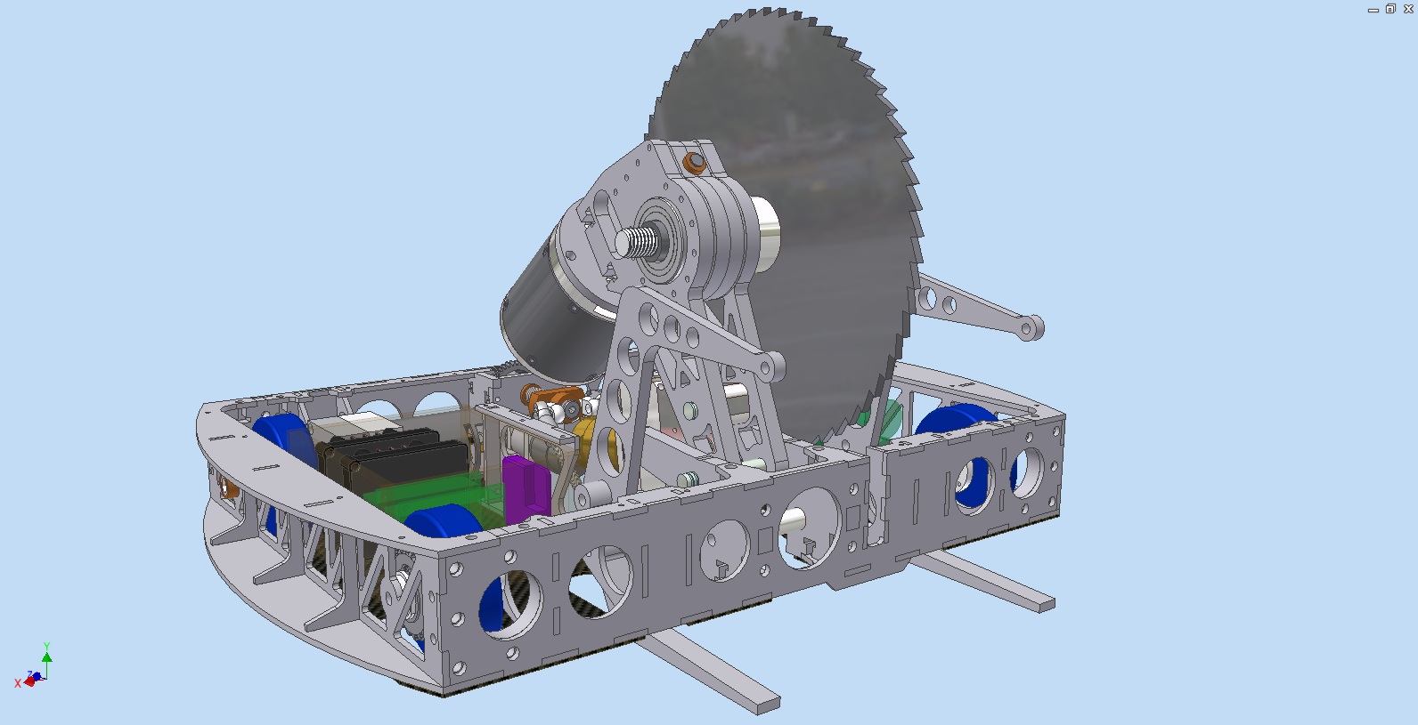
A beauty shot of everything so far.

I discovered the animation module of Inventor and briefly played around with it. Here’s a cool CAD video of the robot mechanisms in action.

The schedule for completion is “ultra fast-track”. I managed to put together most of Clocker in two weeks, so this robot should be no different. Let’s hope I’m right.

HERE WE GOOOOOOOOOOOOOOOOOOOOOOOOOOOOOOOOOOOOOOO

The Fall 2009 Roundup: Überclocker Updates, RazEr Redux, Analog Antics, and the End of the Tragedy of the LOLrioKart

…wins for the longest post title EVER on this site. That’s because it addresses quite a few topics. I can finally characterize the academic term so far as having entered a steady state, which just means I know which nights I can bumble away safely, so it’s time to step up work on the projects. I’ve devised a list of theoretically attainable goals for the next few months, stretching into the coming winter months.

Überclocker Remix

Let’s start with some pictures of epic motor ownage. I cracked open the toasted HTI gumball machine motors out of curiosity after removing them from the bot. What awaited me inside was a scene of utter devastation.

That doesn’t look very healthy. It appears the commutator decided to just melt off the backing material. This motor actually still ran, just throwing blazing white sparks everywhere. The discoloration of the copper next to the crater attests to the extreme heating that occured.

The brush cap from the left side, which simply failed open circuit at the event. Well, now the reason is clear why it failed open. Half of the brush conductor spring just sort of flew off and melted itself into the other side of the plastic brush holder.

The carbon brush itself was bouncing around inside the motor.

Another view. That bit of spring must have been pretty hot to instantly melt itself into the plastic.

And another view of the copper droplet that is the commutator. Oddly enough, the windings themselves seemed for the most part to be just fine.

Here’s Überclocker looking decrepit on a table. Since a robot with no motors is akin to a dog with no legs, or a fish with no fins, I began the quest to search for a… well, more legitimate motor. That’s when I remember that I found these, from Way Back.

DeWalt drills are classic musclebot motors. Sadly enough, these were of different voltages (!?), which not only surprised me as to how on earth their previous user expected their creation to move in a straight line, but saddened me because I… well, want mine to.

It was enough to perform a fit test and draw up plans to modify the gearbox to accept these motors while UPS channels their Brownian Motion to get a matched set of motors to me. They are the “new” DeWalt motors, where “new” is relative to 2003 or so. These drills have 3 speeds and are infinitely more of a bitch to mount. So I will only be using the motors in my custom frakenb0xen.

Fit test. The good news is that these motors are roughly the same length as the 700-size HTI motors, but a little fatter. No issue, considering the gearboxes have plenty of wiggle room.

The gearbox modified to accept a DeWalt motor, with its Alien Technology Motor Pinion of neither metric nor Imperial tooth pitch. Needless to say, this will be removed and the HF motor pinion crammed on in place.

So am I over-motoring the HF drill gearbox parts by putting a real motor on them? Perhaps. However, I think it’s a legitimate move in a 30 pound robot, because the laws of physics dictate that I can only put so much power to the ground. I’m mostly after the “real motor” bit, not so much increased drivetrain power, because the robot doesn’t have the traction to use it.

With motors now on the way, this conversion ought to go quickly since I’ve already drilled the new mounting holes to accommodate them. Überclocker should then be able to attend more events.

The (Possibly?) Final Chapter in the Tragedy of the LOLrioKart

So by now all ya’ll have probably heard of this.

While the details surrounding the citation were totally illegitimate and imply a degree of recklessness that was not present at all, the bottom line is that the kart is not going on any more open road adventures until it’s legit. And by legit, I mean registered and insured and fully street legal.

Whatever measure this takes, it will happen. It will simultaneously the most confusing and most glorious thing on the planet.

But the good news is that through two weeks of intense demos and driving during Orientation, the kart didn’t explode. The motor controller, version 6, is more or less stable. That’s huge. That’s like, me doing something right in electronics for once.

Of course, if I actually run the numbers on the electrical characteristics of the power converter, it would probably make real EEs run away to vomit. But the kart has survived more than twenty power cycles without misbehaving, save for the flakey DC-DC converter that caused the initial failure of version 6. A replacement module with better-designed (read: existent) filtering solved the problem.

So I’m satisfied. There will be little active work on LOLrioKart this term, with most of the fleeting effort concentrating on the battery system. After said weeks of operation, two cells in the battery pack are now just resistors. I regularly saw the voltage dipping under 45 volts on acceleration, which is concerning to say the least. Battery management solutions are condensing around me, so I may make the jump to lithium iron phosphate cells.

Now let’s move onto the new shiat.

This is a Xootr Street push scooter.

Gee, that looks kind of like every other push scooter on the planet. You know, like a Razor scooter. I thought you already had one of those? With like… a motor on it, right? That you built? I heard you built a motor. Can you show me how that works? Can you build me one?

… </average_miters_visitor>

Oh, that’s the difference.

As much as I love RazEr when it works, it’s time for me to realize that it’s too freakin’ small. I’ve managed to hit the tiny-but-functional goal, and at the same time the maximum recommended rider weight a few times. With some more scrupulous design, I could probably fit more batteries in there, but otherwise all the useful space is essentially occupied. And while 5 inch wheels are great for shoving your average copier motor core into, they are not great for shoving into your average pothole.

I need something bigger. More legit™. So thanks to MITERS for coming up with an engineering sample of the Xootr Street. I won’t actually be making any mods to this one, since it’s … not mine, and stuff.

This thing measures a bit over 3 feet long when fully deployed. The wheels are 7 inches in diameter and cast aluminum. It’s the smoothest thing ever on the ground because of the large wheel-to-bearing diameter, which minimized rolling friction. And the deck is absolutely enormous….

… and HOLY MAGNESIUM JESUS ON A STICK. It is in fact CNC machined from billet aluminum. These guys are just like me, except with infinitely more style. A scooter? Made from real metal?

And the 10 center-side pockets are just big enough to comfortable seat two A123 26650 cells apiece! How about that. 20 cells yields almost 150 watthours of battery pack energy.

Ground clearance check. The deck height, oddly enough, is almost the same height of the Razor A3 frame. The wheel line is just an inch and a half or so higher to fit the 7″ wheels. Overall, as can be seen, there is about 1.25″ of “fiddle space” from the bottom of the deck (not including the pockets) to the top of the 1.5″ parallel.

This is good, because hiding all the goodies under the vehicle frame contributes to vehicle aesthetics and the illusion that something which is not supposed to be motorized is moving under the directive of an unknown force.

There are no motor drawings or plans for this yet, but the profile of the wheels and their spacious internal diameter make them amenable to stuffing axial flux coreless motors inside, maybe even one per wheel. I’ve been itching to build a real surface-wound (no iron core) pancake motor for a while, but have been put off by their complexity in manufacturing.

As more details condense from the bot-aether, I’ll give this project its own page, category, and possibly a snappy and witty name. This is not a high priority project, as I don’t even have the vehicle yet, and it might spill over into Spring term.

Spring is a better time to blaze around anyway.

Now Announcing Project SEGFAULT

Segways.

A bad pun on the word segue. A fundamentally unstable faceplant-waiting-to-happen of an inverted pendulum. A cool exercise and great demonstration of basic control theory.

DIY balancing personal transporters have been attempted and perfected many times before. It’s almost passè. There’s even instructions on how to do it and code for your choice of microprocessor. All you need is two fat motors, a rate gyroscope, an accelerometer, and determination.

The whole thing about “microprocessors” is what has been putting me off. I like to think I’m familiar with mechanical engineering principles. I’m shake on electronics and EE. But I’m the last person you want to ask about anything software related. I hate software. With a passion. Even though I use it ALL day, I shudder to see what goes on under the glitzy Web 2.0 interface, or under the ultrasonically-welded sealed cap of an Atmel chip.

…so that’s why I want to do it all in ANALOG ELECTRONICS.

That’s correct. Op amps, comparators, linear components, passives… it’s a 6.002 (or 6.101) paradise. I stochastically arrived upon this idea near the beginning of the term, but it took a few weeks before I took it upon myself to do some research on gyros and accelerometers, and sketch out a rudimentary control network composed primarily of rail-to-rail op amps.

Then I remembered that Dale had built an analog balancing robot, so naturally I read the site and discovered I was doing it totally wrong.

I have a sneaking suspicion that a relatively non-chaotic differential equation like the one that governs inverted pendulums can be pretty easily translated to a continuous time control system (analog, as opposed to a discrete time digital control system). The idea as a whole is to have a purely analog, continuous-time front end controlling a Class D amplifier, also known as a switching amplifier or if the output is bidirectional a locked antiphase amplifier. Basically this just means your transducer wiggles back and forth really quickly… but some times more in one direction than another, so the summation of the movements is a velocity.

But Charles, isn’t a switching amplifier a digital thing?!

Yeah, if I implemented a real linear motor driver, I would have a battery life of 30 seconds and require heat sinks the size of Hannah Montana. Sssshh…. don’t tell anybody.

With the plan now more grounded (HURRRRRRRRRR PUN) than before, I’m moving forward with the mechanical details, as I always tend to do first. Once I have a rolling frame, I could conceivably roll analog or digital, or mixed-signal. As always, this entails a trip to MITERS and a few hours of mining for parts.

Yeah, so it’s nothing much yet. I grunged these 9″ pneumatic tires for the project as they were the only two matching wheels in MITERS that weren’t already on something.

9 inches? Isn’t that a bit small (&thats_what_she_said;) ? It is, but there’s nothing fundamentally wrong with having smaller wheels on such a machine. It just makes obstacle negoatiation tougher. If anything, I can get away with having less torquey motors because of the increased mechanical advantage.

The design work continues! After I get my control theory a bit more in line, I’ll sketch up a schematic of what I think should work. There are endless supplies of linear circuit components at MITERS and kicking around the EE labs for experimentation. I have accelerometers and gyros on the way from Sparkfun for experimentation.

…Oh, that’s the other cheat here. Real, modern MEMS sensors. I’m going for the analogginess here, not period-realism.

SEGFAULT will get its own page and category as it develops. This is my number one goal for the end of the term, and I’m actually going to try to get the controller graded. Here goes… something!