Überclocker: T minus 5

Since the last Überclocker update, a ton of work has been done on the bot. This past weekend, I purposefully trapped myself in the shop for the duration of the Snowmageddon Snowpocalypse Snowlingrad Snolocaust Great Leap Snowward Snowtorious B.I.G. which shut down most of New England for Friday through Sunday, to get as much done on Clocker as possible. I’m proud to say that at this point, the bot is driving (but not yet lifting). This following report will basically summarize the work of the past week or so, including all of this past weekend – otherwise, there’s going to be like 90 pictures!

I began by tackling basically the only menial machining task on the bot: making the Springy Legs. The “raw forms” were waterjet-cut from 3/4″ aluminum with the intention of finish machining.
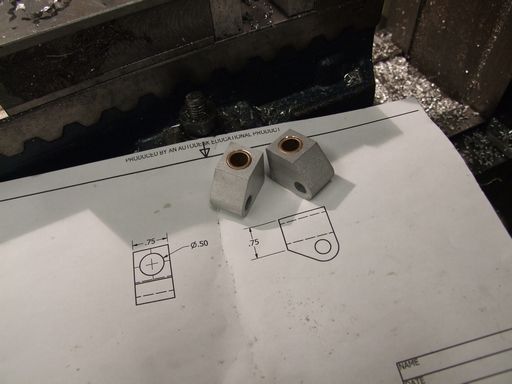
This is the stationary rear portion of my DIY shock absorbers. They just have a hole drilled through to hold a bronze bushing, which will interface with the “rod”, a shoulder screw.
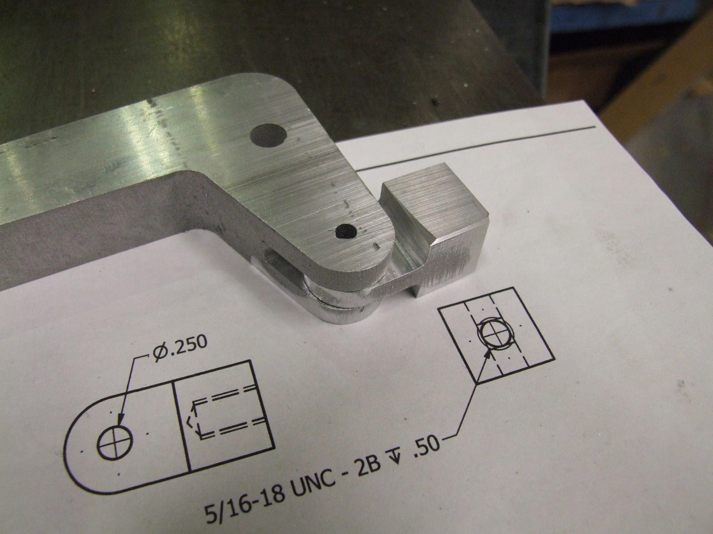
The other two parts were a little more interesting. The trunion end of the shock absorber is doubly supported in the leg itself, so it meant I had to cut a roughly 0.8″ deep slot in the leg. I broke out, fortunately not actually breaking, my long-cut 1/4″ carbide endmill from the days when I collected tooling and carved it in 3 passes.
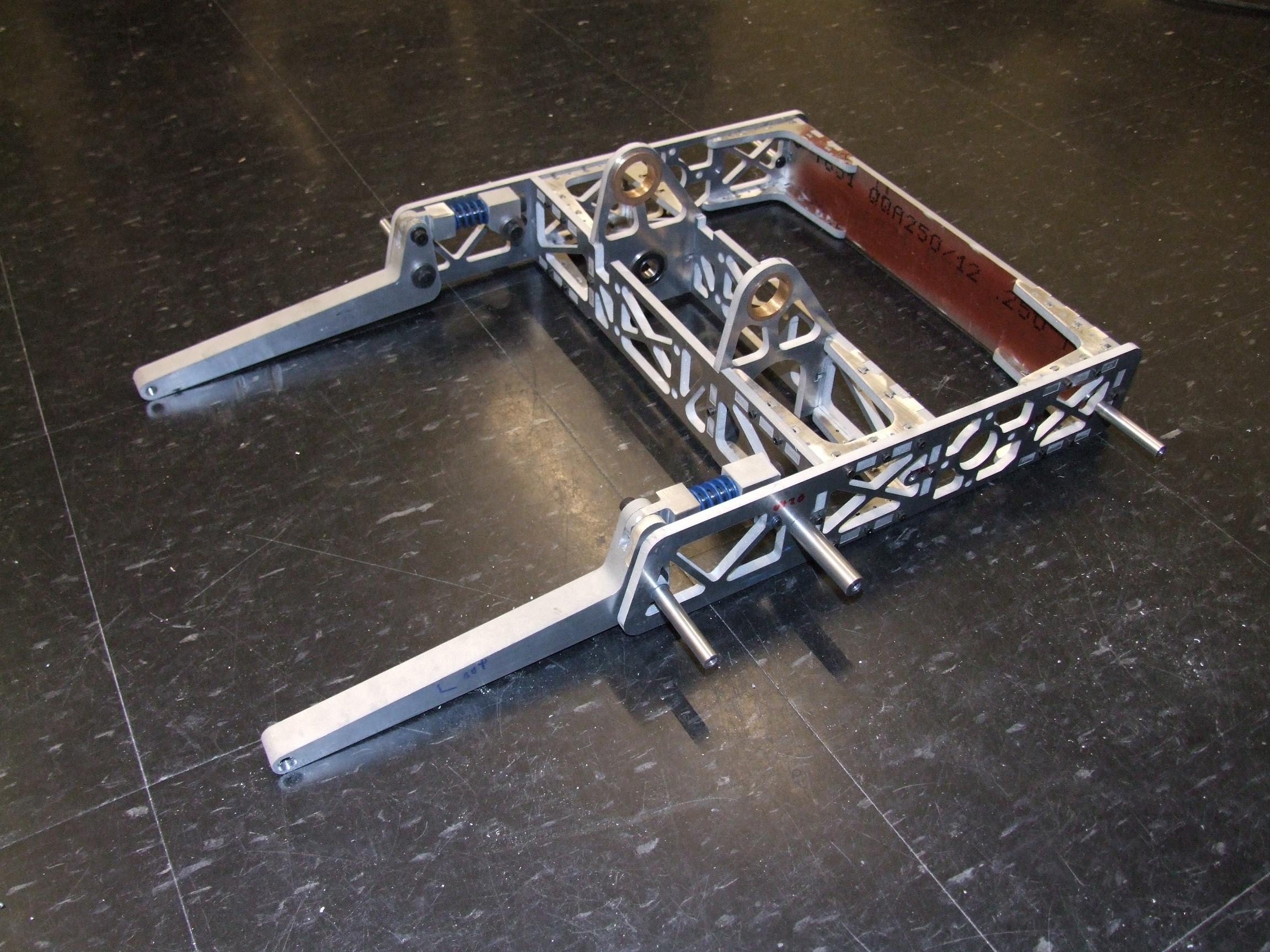
After most of the little menial machining objects were done, this is the state of the frame. I have a set of stiffer springs in case I find these too ‘soft’. If the bot lurches forward too much, it could hinder the lift by just keeling over at the very front of the legs.
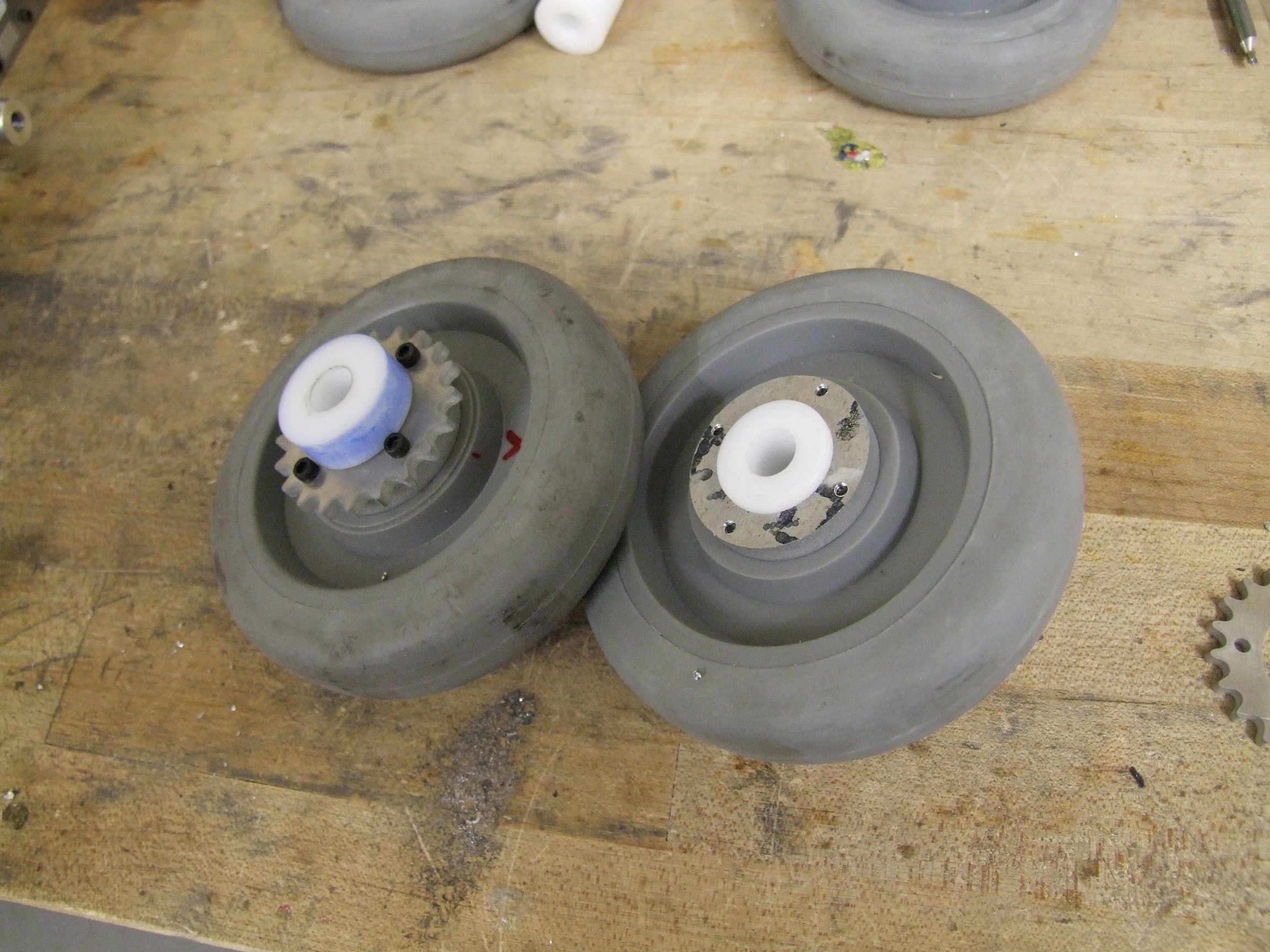
From there, I moved to making the wheel hubs. These are based heavily on my design used in Clocker’s summer Gritty Reboot, but with a bigger Delrin center and larger diameter spacers for the larger sprockets. I started with a 1″ Delrin round and quickly whipped them out on Tinylathe from there.
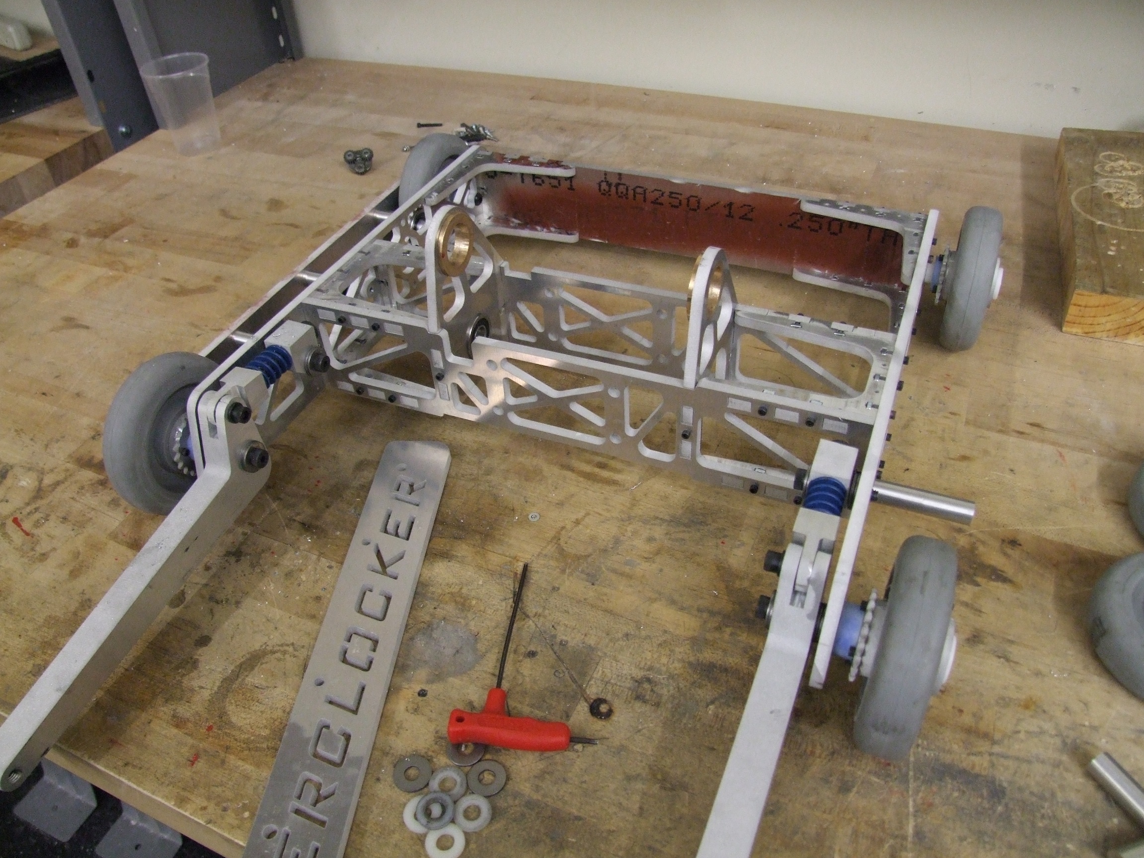
Starting to reach Criticality (where a project can finally support its own weight)… I found a pile of nylon and steel washers to space the legs out properly. From there, plenty of blue Loctite was poured into the standoff-axles, forming the “permanent” side of the attachment. If I ever have to replace the legs, though, I’m kind of boned.
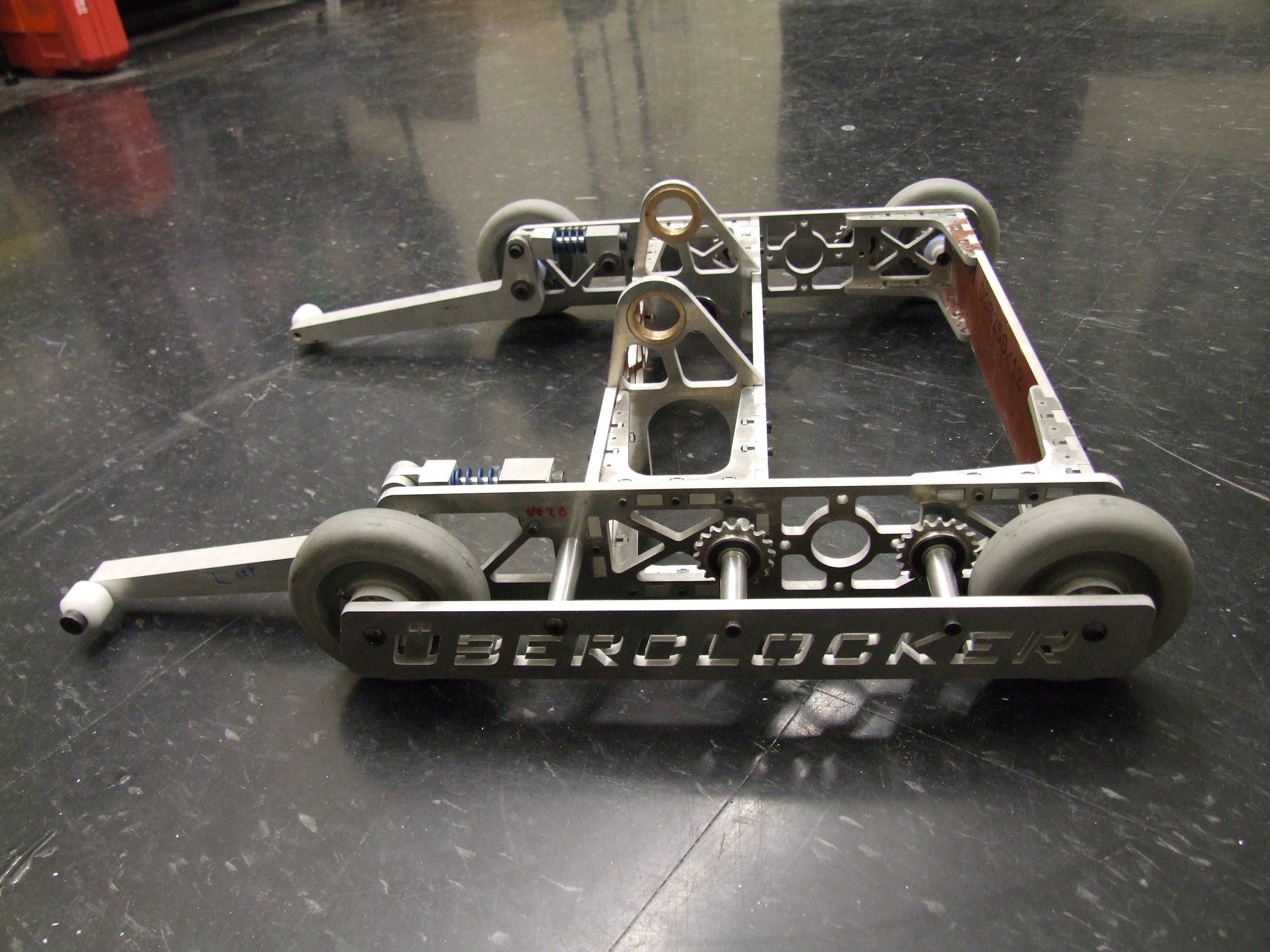
I christened this thing “Clockerboard” since I was riding it like a skateboard for a little while. The frame is extremely rigid, and the precision-ground aluminum standoff axles pair well with the Delrin hubs. The action is so smooth it might as well be on real bearings.
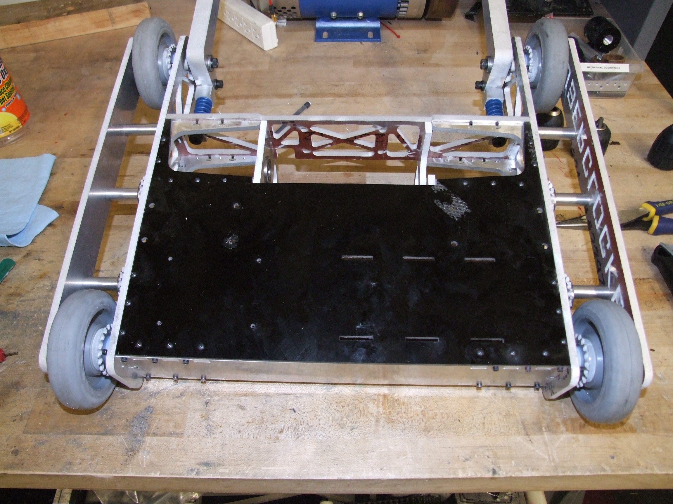
And the bottom plate goes on. I clearance-drilled the pilot holes in the bottom plate and made the attachment with #4 button headed screws. I normally despise buttonheads because of their super small 1/16″ hex key size, but they offer more bearing area (larger head) than the regular cap screws, which is better for the garolite’s structural integrity.
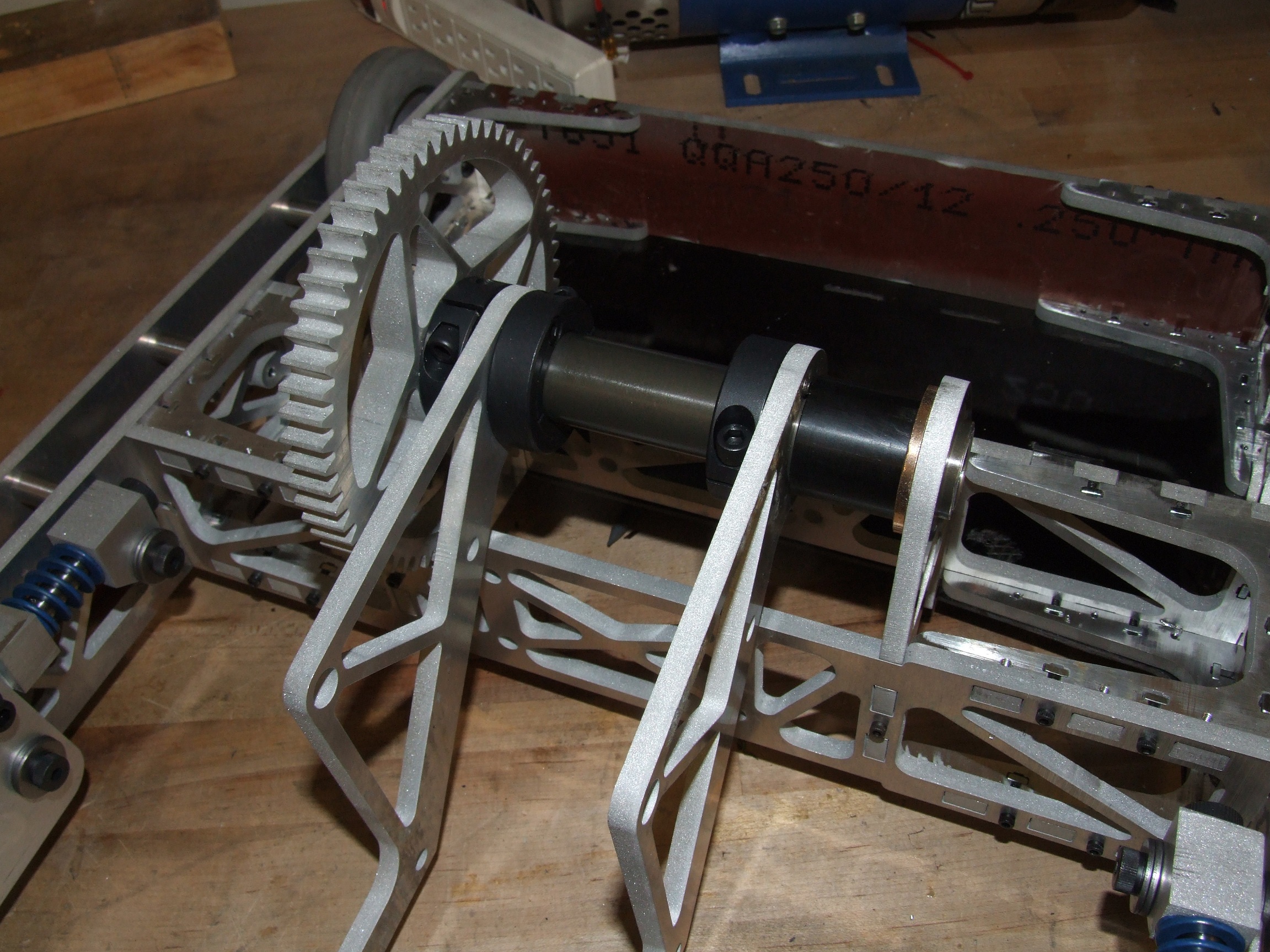
Starting from a 1″ diameter chunk of ceramic-coated (hard anodized, anyway) aluminum shaft, I drilled out the entire center with a long .75″ drill bit to save weight, then started putting the fork asesmbly together. In lieu of using retaining rings on the ends of the shaft, as originally planned, I decided to just machine spacers to span the gaps between forks in order to take up the axial slack. There was already going to be 3 different shaft collars constraining movement axially – a little snap ring wasn’t going to add that much more to the equation, and I could not be buggered to try and find the only grooving tool within 2 miles.
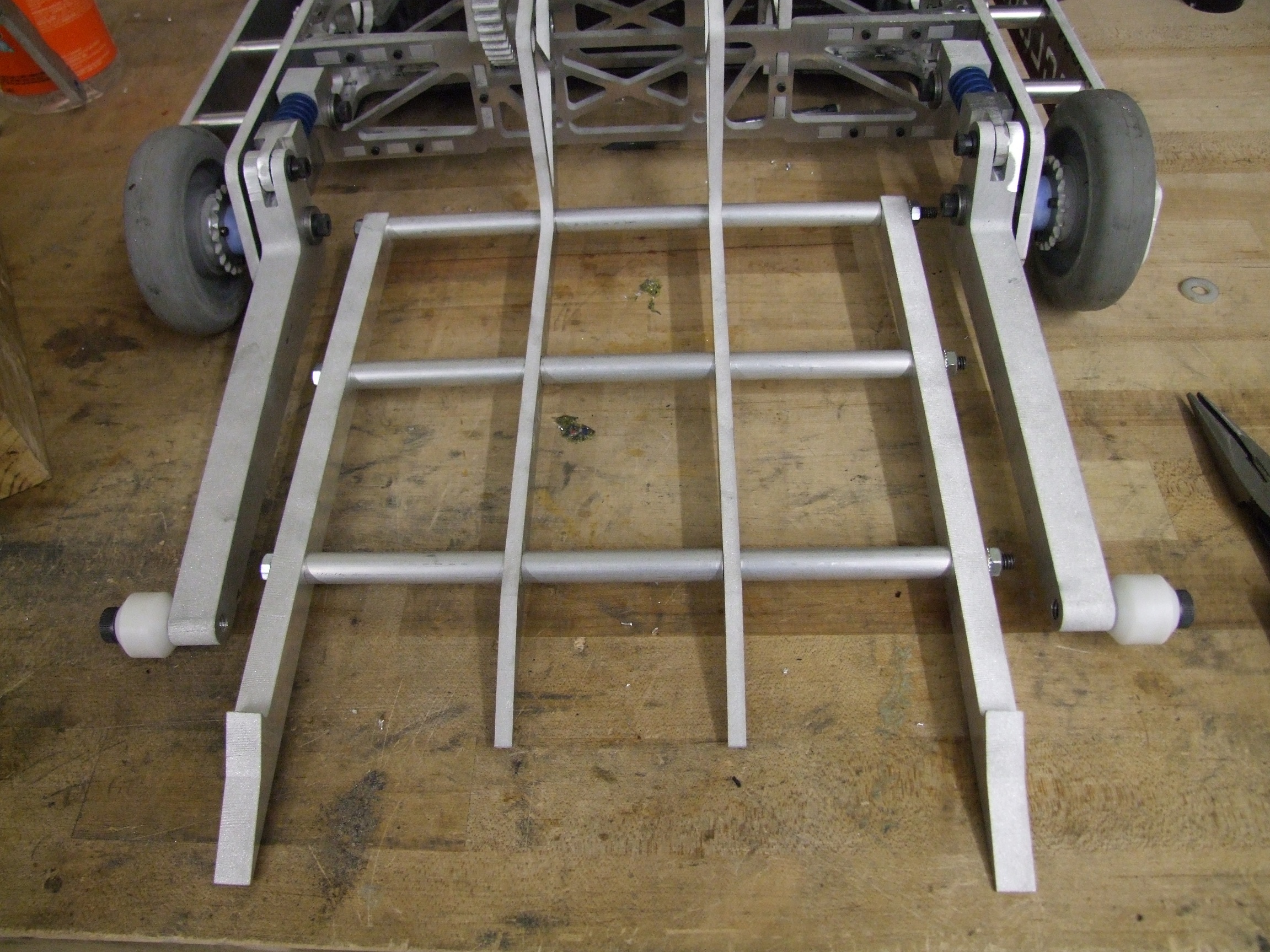
After cutting out some lengths of threaded rod, the fork comes together. This assembly is extremely rigid because of the sheer amount of preload I’ve put into this system through the three alloy steel threaded rods.
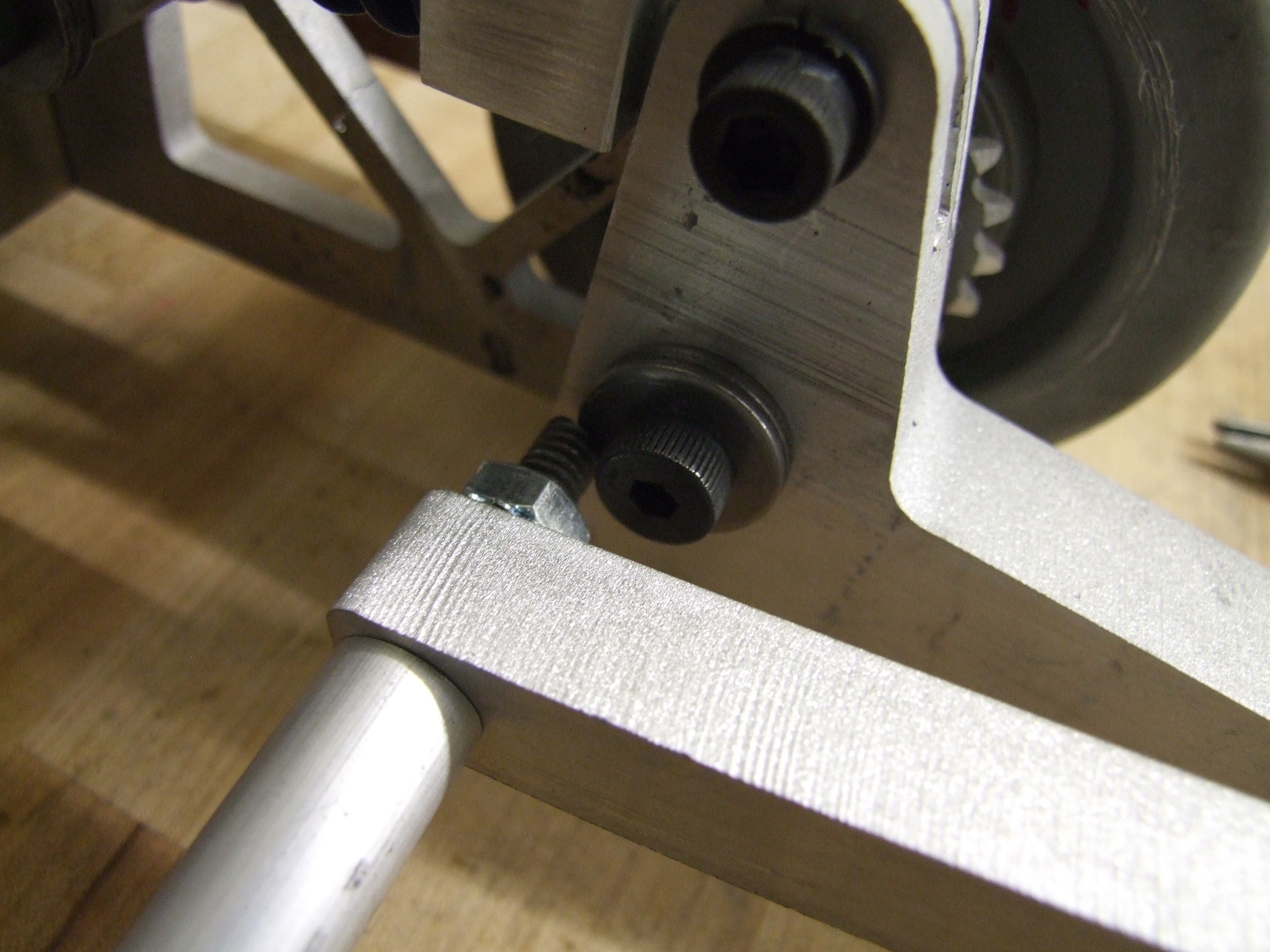
…unfortunately, I forgo that screws have heads.

The real story here is that the shoulder screw holding the leg on sticks out further than in the design because I added the spacing washers to give the leg a wider bearing area. I didn’t account for the extra width of a locknut compared to a regular nut, either. So the result, unfortunately, is just the hardware running into itself.

No problem – cutting the threaded rod exactly to length, and shortening the outer spacers 1/8″ each, gave enough slop room to clear the fork.

The modified clamp actuator goes on with, you guessed it, some more shoulder screws.

Mid last week’s pretend-o-bot, or thereabouts. This was just before the DeWuts showed up, so at this point I was stuck until I had motors. Luckily, Anonymous (…Chinese CNC shop) delivered.
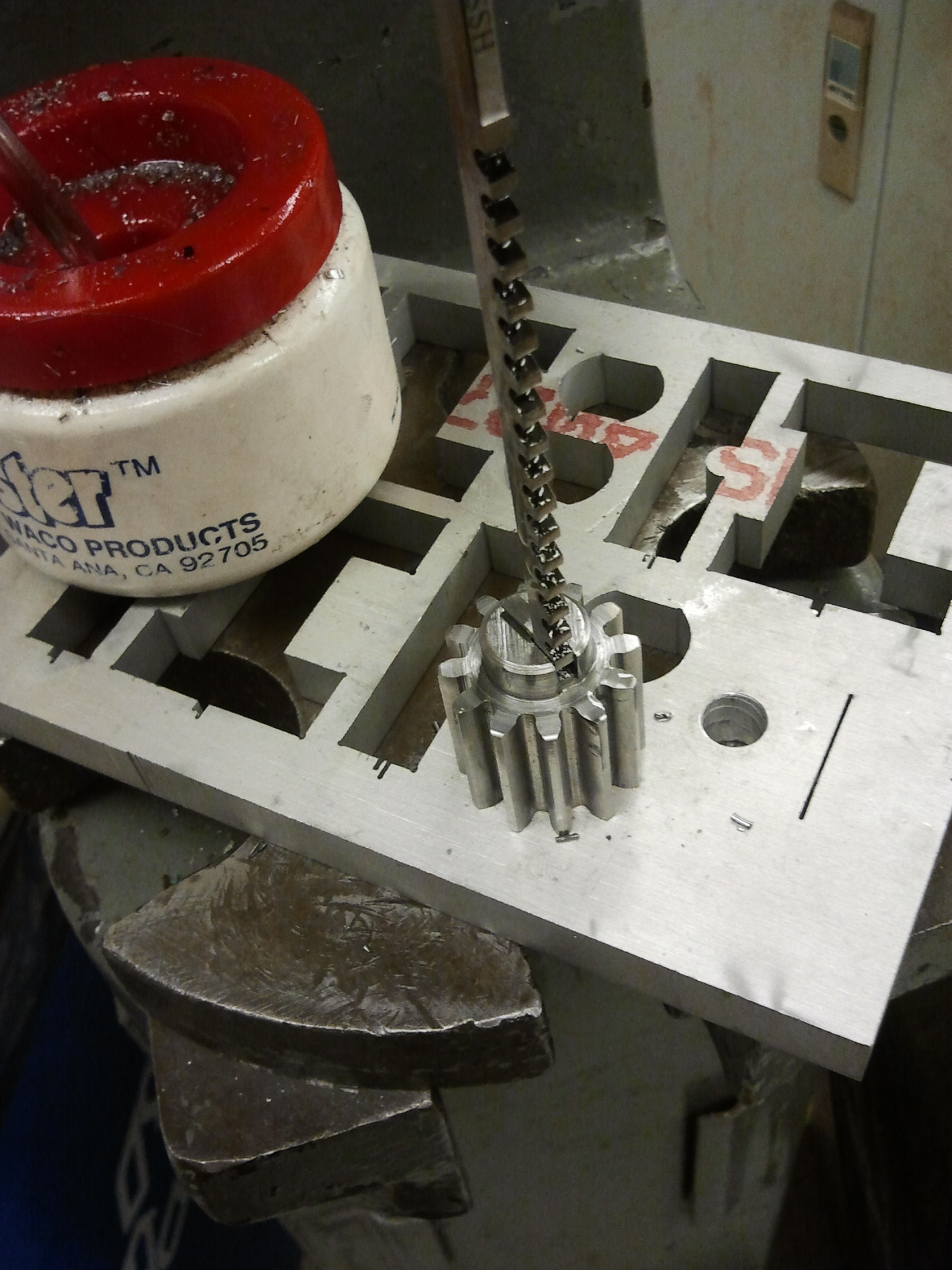
While waiting for the DeWuts, I decided to take care of the rest of the menial machining tasks. I purchased a 1/8″ keyway broach to make the key cuts, and went to the Edgerton Shop to use a long-throw arbor press to cram the thing through the gears and sprockets.

With the DeWuts having finally shown up, here’s one of the first pictures from the mid-snowstorm robot work: one drive motor with shaft trimmed and test mounted. To be honest, I was mostly distracted by finally being able to run Landbearshark in its native habitat to get substantial robot work done…
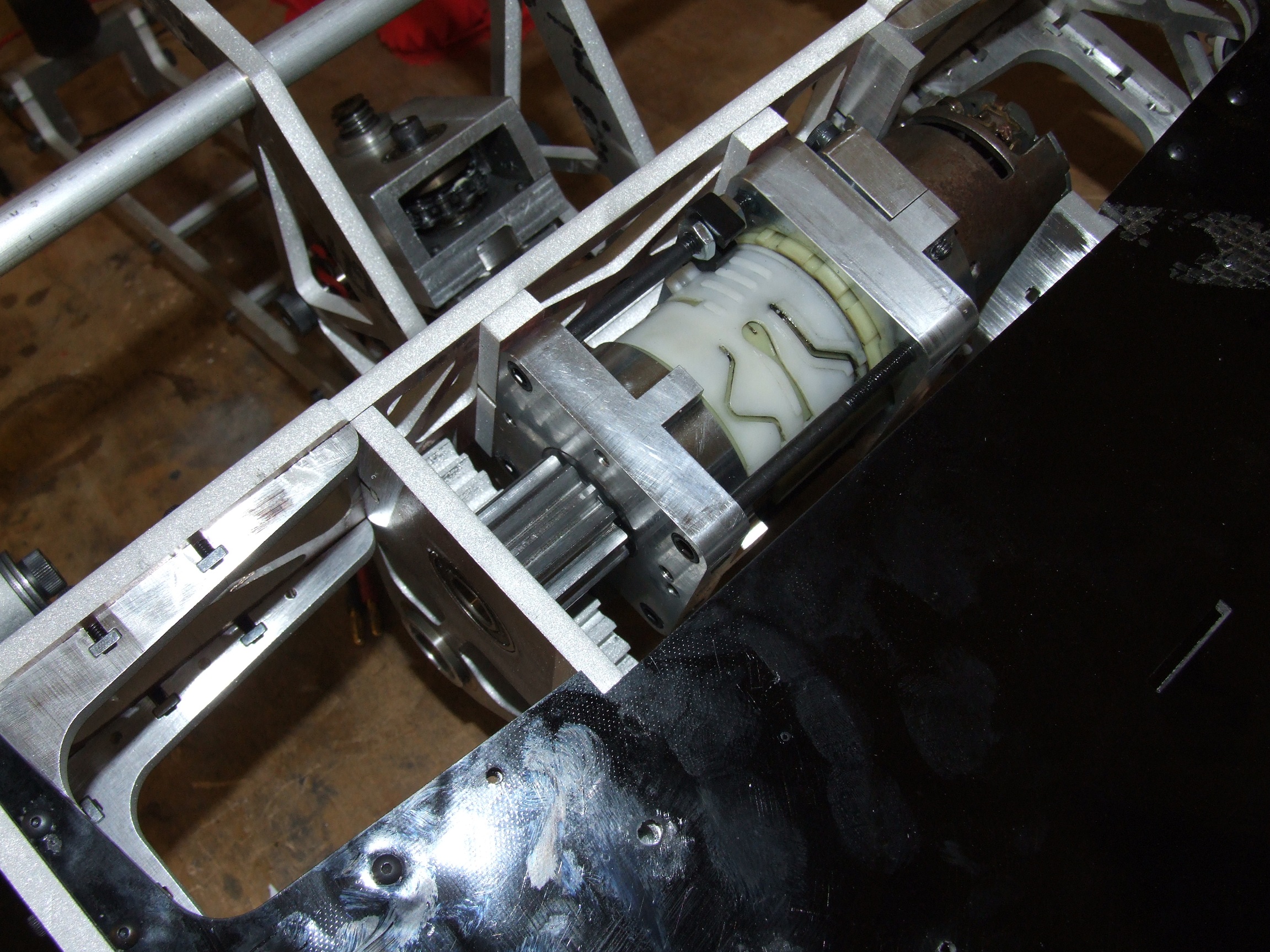
I also went ahead and mounted up the lifter motor. It’s attached to the frame through a big U-bracket which functions as a spacer, the bot cavity being 1/2″ wider than the motor.
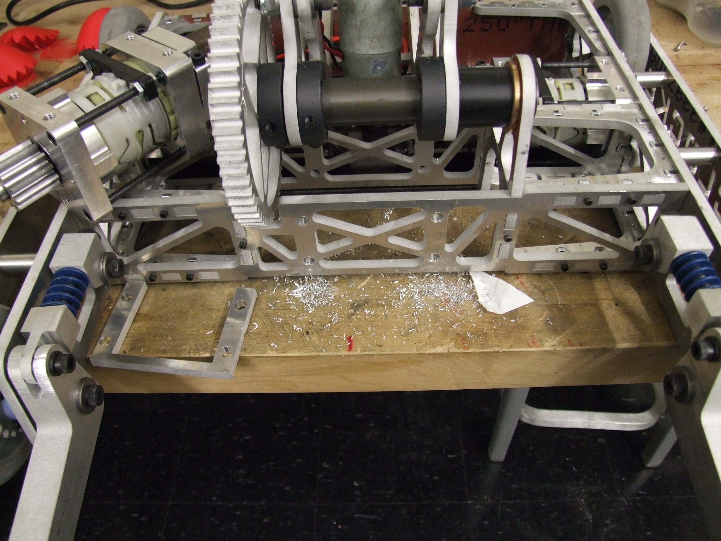
One issue was that the final distance between mounting holes was basically 3.00 instead of 3.05″, the original anticipated design length. I’ll have to take measurements of multiple units in order to confirm the +/- deviation from 3.00″ I should report, but the 3 on Clocker are all pretty close. Either way, much clearance-drilling was required. I basically had to open these holes up to 5/16″ to make that fit.
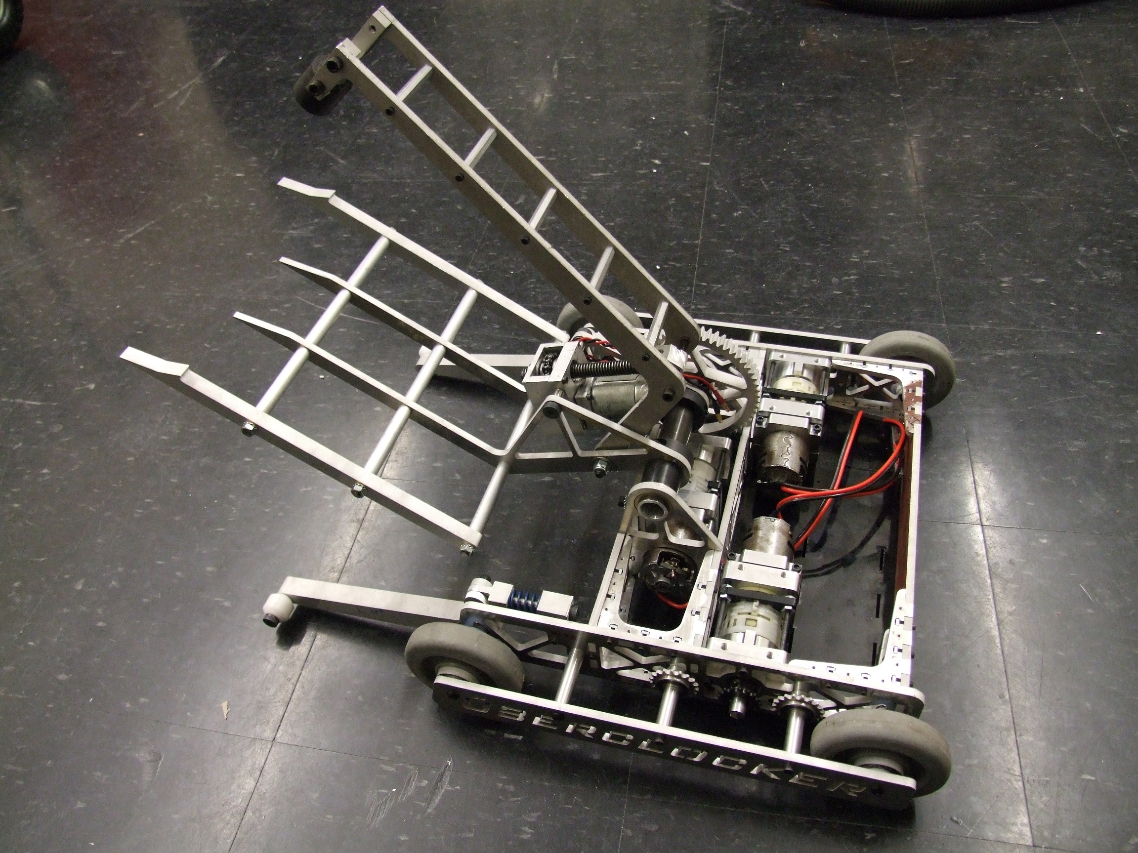
Drive motors mounted. By this point, I think the snow depth was already 18″ and going. The pickup truck plows had given up, and heavy equipment was starting to roll through the streets.
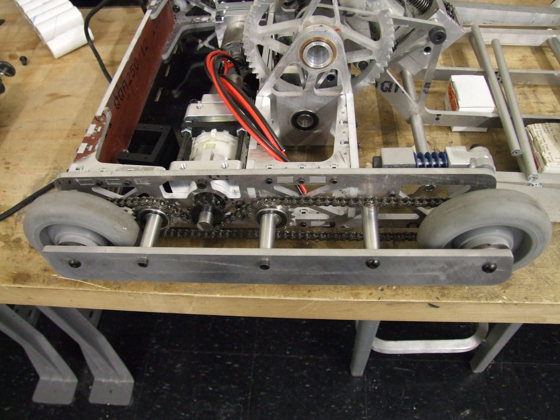
The last task of the night was routing the chains.

The chains on this version of Clocker are routed a little interestingly. On this (right) side of the bot, the chain wraps around the bottom of the sprocket. On the other side, though, the chain wraps over the top of the sprocket (and hence under the tensioner sprockets).

I did the chains up this way on purpose because the DeWalt motors are very heavily timed to favor one direction: the drilling/screwing-in direction, or counterclockwise. You rarely use a drill in reverse, so manufacturers squeeze a bit more forward power out of the motor by optimizing the brush timing for one direction.

In a traditional two-sided drive robot, the motors have to spin opposite directions to effect forward or backward motion since they are mounted mirrored from each other. In the DeWalt’s case, it seems to cause up to a 10% speed difference between sides – that means the robot will just pulll a huge wide turn the entire time you command ‘straight’. Clocker Remix, in fact, does this – it has never ‘driven straight’ in testing.

In practice, combat driving never really sees enough straight line travel for this to matter much, so most people just straight up ignore it.  If I had the opportunity to make the bot more symmetric, though, I was going to take it. So, to power the bot forward, both motors in fact rotate counterclockwise as viewed from their own shafts. This is the favorable timing direction and the difference in speed is both audible (faster spinning, higher pitched) and visible (the bot is definitely slower going backwards).

As for the chains themselves, I incrementally dialed in the tensioners by running the chain for a few minutes, then moving the tensioners to tighter positions. Chains stretch a few % just by virtue of wearing in the first time, so this was critical.

That concludes the first round of work. In the past day, I’ve managed to wire up half of the bot, but that will be reported on shortly. Tomorrow I anticipate being able to start doing shakedown tests and figuring out what to tune before the event.

The Forthcoming RageBridge: Stick Calibration

They’re here!

All of the RageBridges! All of them ever!

Or rather, 100 of them, in neatly packaged panels of two. Here’s what one of the manufactured panels looks like.

Pretty cool.

Okay, so these actually got in last week, but I’ve been doing some background and infrastructural work since then. I’m planning on gathering a few friends and flashing, populating headers, and testing all of these this coming weekend. I decided to leave the chips unflashed because I was not yet satisfied with the firmware (and the flashing was a few hundred extra dollars), and the headers are purposefully left unpopulated because many people prefer soldered-on pigtails or their own wiring configuration. It’s definitely a little more legwork on our end, but for such a small run (100, maybe with a few duds) I think it’s still manageable, and will allow the fine settling into best practices that inevitably accompany any parts business. Time to be a little adventurous.

From a firmware perspective, the only thing RageBridge has been missing since the last board revision is a way to calibrate the servo PWM range. This is generally preferred because not all radios are created equally, and some may have more stick travel & adjustable PWM endpoints than others. For instance, my (nice for 2006) Spektrum radio can hit the full 1000-2000uS servo range if I navigate through the menus and tell it to stretch its range a bit. But my cheesy Hobbyking 6 channel radios can’t do the same unless connected to a computer to program them – the stock range is more like 1200 to 1800us. So, any fixed input range will inevitably be a compromise – for some people, the stock settings will be too twitchy (i.e. stick travel range is greater than the board’s accepted input range), or you might not ever hit full throttle (because the radio stick travel doesn’t go far enough to match the controller input range).

Calibration has always been one of those things that I accepted as working, but never thought about implementing. Depending on how it’s done, it can be relatively simple, or a mess of state machine code.

One of the most common modern calibration paradigms is the “stick-high” method, used by most R/C model controllers, whether air, sea, or ground. This involves powering on the controller with a receiver attached (and generally, already powered and outputting valid pulsewidths) and you commanding full positive travel. If the first thing that the ESC sees, or sees within 1-2 seconds, is a full positive signal, then it waits for a few seconds and checks again. If you are still holding full positive, then it beeps or blinks (accepting the full positive position), and then you back off to full negative and hold for a few seconds, then back to neutral. For single channel ESCs without many other features, it’s pretty much the way to go.

I decided to implement stick-high calibration for RB, except modifying it for both channels at once. This entailed adding a timed loop in the middle where normally you would just check for full positive and full negative signals. The idea is that during the timed loop, the user just swirls the sticks around all at once and the controller will capture both ranges simultaneously. At any point, if the signal returns to neutral for more than 2 seconds, the calibration routine exits and writes the results to EEPROM so it is persistent.

Of course, there’s other little touches to make the system more robust like checking for pulse validity (rejecting malformed or misread pulses) and fail-safe performance if the user bails out in the middle. In all, it took me a few hours of planning and a few hours of beasting Arduino code, and I’m quite pleased with the final result.

So, in a completely out of context brain bump, here’s RageBridge’s stick calibration code. When I ship it through e0designs.com, the full source code will be released along with board files, but I’m putting this early because I’m particularly proud of it.

I subscribe to the Expository Essay school of code commenting – I literally write what every line and every procedure does, in detail, and in natural english. To hardcore and experienced coders this might seem like a waste of characters, but I find it particularly easy to read my way back through old code and decipher what the hell I thought I was doing when I wrote it. So there’s actually plenty of paragraphs in the comments.

As a bit of backstory since I didn’t post all the variable definitions, anything with a _1 or _2 is referring to the channel of RB it is relevant to. The code is written with Arduino 1.0.1 using the PinChangeInt and EEPROM libraries (PCI is not used in this section as the interrupt procedures that capture servo pulsewidths are not shown).

  • RCMAX, et. al. are all declared as signed integers at the beginning of the code (not shown).
  • CALIBRATION_CONSTANT is a fraction of the total stick travel, right now 0.66. In other words, anything ABOVE 66% of the current maximum travel is grounds for entering calibration mode. This is one of the tricks I added to prevent calibrating yourself out of your own radio travel bounds. So, basically what it entails is each time you calibrate you could reduce the range by 1/3rd if you had to.
  • neutral_counter and NEUTRAL_CYCLES_MAX refer to how many iterations of the neutral signal checking routine can run before the calibration procedure is declared to be done.
  • NEUTRAL_DELTA is the pulse width deviation around the current neutral point that can be recognized as a new valid neutral point. For instance, the default neutral pulsewidth for servo PWM is 1500us. If NEUTRAL_DELTA is defined as 100, which it is, then anything from 1400 to 1600 may be set as a new neutral point. This is to make sure you cannot drift the center stick zero throttle point too far, even on purpose. You can, of course, do so by running multiple calibration cycles. But why!?
  //Collect the user calibration endpoints from EEPROM. If the EEPROM values return 255
  //then calibration has never occurred, so use defaults.
  RCMAX_1 = (signed int)EEPROM.read(100);
  RCMAX_1 += (signed int)(EEPROM.read(101) << 8);
  RCMIN_1 = (signed int)EEPROM.read(102);
  RCMIN_1 += (signed int)(EEPROM.read(103) << 8);
  RCCENTER_1 = (signed int)EEPROM.read(104);
  RCCENTER_1 += (signed int)(EEPROM.read(105) << 8);
  RCMAX_2 = (signed int)EEPROM.read(106);
  RCMAX_2 += (signed int)(EEPROM.read(107) << 8);
  RCMIN_2 = (signed int)EEPROM.read(108);
  RCMIN_2 += (signed int)(EEPROM.read(109) << 8);
  RCCENTER_2 = (signed int)EEPROM.read(110);
  RCCENTER_2 += (signed int)(EEPROM.read(111) << 8);

  //Bytes will return 255 if they were never read; full 16 bit result is 65535
  if(RCMAX_1 == 0xffff ) {
    RCMAX_1 = RCMAX_DEFAULT;
  }
  if(RCMIN_1 == 0xffff) {
    RCMIN_1 = RCMIN_DEFAULT;
  } 
  if(RCCENTER_1 == 0xffff) {
    RCCENTER_1 = RCCENTER_DEFAULT;
  }
  if(RCMAX_2 == 0xffff) {
    RCMAX_2 = RCMAX_DEFAULT;
  }
  if(RCMIN_2 == 0xffff ) {
    RCMIN_2 = RCMIN_DEFAULT;
  } 
  if(RCCENTER_2 == 0xffff) {
    RCCENTER_2 = RCCENTER_DEFAULT;
  }  

  delay(1000); //Just chill for a bit to make sure radios have bound and begun sending out good signal.

  //Calibration mode procedure.
  //After initialization, check for good signal on channels 1 and 2
  //If the signal is above the calibration threshold on both channels, keep waiting. If not, enter main program loop.
  //If at the end of 5 seconds the stick has been held, enter calibration mode. If it has not, enter main program loop.
  //Even if there is no good signal, proceed to main loop anyway - the main loop begins in failsafe mode. 
  if(is_pulse_good(vol_ch1_pw,RC_ABS_MAX,RC_ABS_MIN) && is_pulse_good(vol_ch2_pw,RC_ABS_MAX,RC_ABS_MIN)) {
    signed int init_calib_threshold_1 = (signed int)(CALIBRATION_CONSTANT*(RCMAX_1-RCCENTER_1))+RCCENTER_1;
    signed int init_calib_threshold_2 = (signed int)(CALIBRATION_CONSTANT*(RCMAX_2-RCCENTER_2))+RCCENTER_2;

    if(vol_ch1_pw > init_calib_threshold_1 && vol_ch2_pw > init_calib_threshold_2) {

      //To check for stick hold, begin the timer and set a flag that will be cleared if the stick is released
      unsigned long calibration_timer = millis();
      boolean entered_calibration = true;

      //Enter 5 second wait loop, constantly checking for stick release. Invalid signal also constitutes "stick release".
      while(millis() - calibration_timer < 5000) {
        if(is_pulse_good(vol_ch1_pw,RC_ABS_MAX,RC_ABS_MIN) && is_pulse_good(vol_ch2_pw,RC_ABS_MAX,RC_ABS_MIN)) {
          if(vol_ch1_pw < init_calib_threshold_1 || vol_ch2_pw < init_calib_threshold_2) {
            entered_calibration = false;
            break;
          } //End stick release check
        } else {
          entered_calibration = false;
        } //End pulse good check

      } //End wait for 5 seconds to check for stick hold

      //If the flag is still true, then the user has held the stick for > 5 seconds above the threshold
      //Calibration mode description:
      //Resetting the old max and min bounds to a lower threshold (CALIBRATION_CONSTANT * RCMAX_n)
      //If a newly captured value exceeds the thresholds, save it. 
      //If a newly captured value is within a certain % of neutral (NEUTRAL_CONSTANT * RCCENTER_n above or below RCCENTER), start a timer
      //After 3 seconds of this, assume the user has returned stick to desired neutral and take several samples for neutral position
      //If any pulse is invalid, bail out of calibration and retain old values.
      if(entered_calibration) { 

        digitalWrite(BLINK_FURIOUSLY,HIGH); //Set the LED on solid to let the user know that calibration has begun

        //Set initial thresholds to exceed. The thresholds are a certain % of the current set of maxes and mins
        //such that the controller can never be "calibrated out". By only exceeding the threshold very slightly
        //subsequent iterations of calibration can narrow the range of signals too, if it is necessary.
        signed int rcmax_1_temp = (signed int)(CALIBRATION_CONSTANT*(RCMAX_1-RCCENTER_1)) + RCCENTER_1;
        signed int rcmin_1_temp = RCCENTER_1 - (signed int)(CALIBRATION_CONSTANT*(RCCENTER_1-RCMIN_1));
        signed int rcmax_2_temp = (signed int)(CALIBRATION_CONSTANT*(RCMAX_2-RCCENTER_2)) + RCCENTER_2;
        signed int rcmin_2_temp = RCCENTER_2 - (signed int)(CALIBRATION_CONSTANT*(RCCENTER_2-RCMIN_2));
        signed int rccenter_1_temp = RCCENTER_1;
        signed int rccenter_2_temp = RCCENTER_2;

        boolean am_calibrating = true;
        boolean commit_calibration = false;

        byte neutral_counter = 0;

        //Set the main calibration loop going. 
        //First, check for good pulses. If any are bad, the routine is immediately ended and changes are NOT saved.
        //Next, check for pulses near neutral. If any are, increment a counter. If the counter is over a threshold,
        //then the user has returned the stick to netural and calibratoin can exit/changes be saved.
        //If any subsequent pulses are outside of the neutral bound, zero the counter. 
        //Next, expand the pulse range if the new set of pulsewidths are greater in magnitude deviation
        while(am_calibrating) {

          //Sanity check - if any pulses are out of range or invalid, exit.
          if(is_pulse_good(vol_ch1_pw,RC_ABS_MAX,RC_ABS_MIN) && is_pulse_good(vol_ch2_pw,RC_ABS_MAX,RC_ABS_MIN)) {

            //Save a copy of the current "volatile" pulsewidths (which can change randomly due to the interrupt)
            ch1_pw = vol_ch1_pw;
            ch2_pw = vol_ch2_pw;

            //Neutral check. If the signal is within the box of valid neutrals for enough cycles, exit and save changes.
            if(ch1_pw < (RCCENTER_1 + NEUTRAL_DELTA) && ch2_pw < (RCCENTER_2 + NEUTRAL_DELTA)) {
              if(ch1_pw > (RCCENTER_1 - NEUTRAL_DELTA) && ch2_pw > (RCCENTER_2 - NEUTRAL_DELTA)) {
                if(neutral_counter > NEUTRAL_CYCLES_MAX) {
                  am_calibrating = false;
                  commit_calibration = true;

                } else {
                  neutral_counter++; //Within bounds, but not exceeding number of allowed cycles, so increment and move on.
                  rccenter_1_temp = ch1_pw;
                  rccenter_2_temp = ch2_pw;
                }
              } else {
                neutral_counter = 0; //If any of the within-bounds checks fails, reset the counter since the stick has moved.
              }
            } //End neutral check

            //Bounds check; If the new pulses exceeds the current set of temporary calibration bounds in either direction
            //set them as the new bounds.
            if(ch1_pw > rcmax_1_temp) rcmax_1_temp = ch1_pw; else if(ch1_pw < rcmin_1_temp) rcmin_1_temp = ch1_pw;
            if(ch2_pw > rcmax_2_temp) rcmax_2_temp = ch2_pw; else if(ch2_pw < rcmin_2_temp) rcmin_2_temp = ch2_pw;
          } else {
            am_calibrating = false;
            commit_calibration = false; //Something has gone wrong and caused the calibration loop to terminate early...
          } //End sanity check
          delay(20);
        } //End main calibration loop

        //Save changes?
        if(commit_calibration) {

          //First, reassign the constants for this power cycle...
          RCMAX_1 = rcmax_1_temp;
          RCMIN_1 = rcmin_1_temp;
          RCCENTER_1 = rccenter_1_temp;
          RCMAX_2 = rcmax_2_temp;
          RCMIN_2 = rcmin_2_temp;
          RCCENTER_2 = rccenter_2_temp;

          //Next, write these new values to EEPROM!
          byte rcmax_1_lowbyte = (RCMAX_1 & 0x00ff);
          byte rcmax_1_highbyte = ((RCMAX_1 >> 8) & 0x00ff);
          EEPROM.write(100,rcmax_1_lowbyte);
          EEPROM.write(101,rcmax_1_highbyte);

          byte rcmin_1_lowbyte = (RCMIN_1 & 0x00ff);
          byte rcmin_1_highbyte = ((RCMIN_1 >> 8) & 0x00ff);
          EEPROM.write(102,rcmin_1_lowbyte);
          EEPROM.write(103,rcmin_1_highbyte);

          byte rccenter_1_lowbyte = (RCCENTER_1 & 0x00ff);
          byte rccenter_1_highbyte = ((RCCENTER_1 >> 8) & 0x00ff);
          EEPROM.write(104,rccenter_1_lowbyte);
          EEPROM.write(105,rccenter_1_highbyte);

          byte rcmax_2_lowbyte = (RCMAX_2 & 0x00ff);
          byte rcmax_2_highbyte = ((RCMAX_2 >> 8) & 0x00ff);
          EEPROM.write(106,rcmax_2_lowbyte);
          EEPROM.write(107,rcmax_2_highbyte);

          byte rcmin_2_lowbyte = (RCMIN_2 & 0x00ff);
          byte rcmin_2_highbyte = ((RCMIN_2 >> 8) & 0x00ff);
          EEPROM.write(108,rcmin_2_lowbyte);
          EEPROM.write(109,rcmin_2_highbyte);

          byte rccenter_2_lowbyte = (RCCENTER_2 & 0x00ff);
          byte rccenter_2_highbyte = ((RCCENTER_2 >> 8) & 0x00ff);
          EEPROM.write(110,rccenter_2_lowbyte);
          EEPROM.write(111,rccenter_2_highbyte);
        }

        //We're done with calibration! Flash the LED a few times to indicate success.
        for(byte caliblink = 0; caliblink < 10; caliblink++) {
          PORTB |= (1 << 5);
          delay(BLINK_DURATION);
          PORTB &= ~(1 << 5);
          delay(BLINK_DURATION);
        } 
      } //End of master calibration routine

    } //End of check signal over calibration threshold

  } //End of check signal good