Pursuant to my previous discoveries and advances in the field of quadrocopter propulsion using inexpensive generic components, I have commissioned the construction of a tele-operated flying model to demonstrate the practice of the design and construction principles which were discussed in my investigations on the subject I WANT TO BUILD A FUCKING QUADROTOR.
After I evaluated the two flavors of giant Hobbyking ducted fan, I simply couldn’t pass up the opportunity (or resist the temptation) to make a large quadrotor (/quadrocopter) using them. Quadrotors and other flying vehicles have been on my mind for a while, at least since last year; but due to the expense of EDF units, I haven’t ever taken any action on them. The Edgerton Quadrotor, built last year primarily by a group of high school students over the summer, only added to that desire. While I certainly could have built a relatively simple one like that using propellers and cheap outrunners, and it would probably have been more efficient than a ducted fan equivalent, I just don’t like open props. Especially in an application where they have to be horizontally mounted and have the very real possibility of coming straight at my face. Otherwise, as history has shown, I’m just a fan of ……. fans. In other words, I’m embarking on yet another hare-brained engineering adventure that has absolutely no justification for existence. Sounds about on par with everything else I do, right?
I did get to fly the Edgerton quadrotor straight down a flight of stairs, though. And by that I mean it went out of control exactly straight down said flight of stairs… I wasn’t really flying it at the time.
So therefore, I now announce the Emergency Quadrotor Project. The plan: four Hobbyking 102f type EDF units, four of the 600-class helicopter motors, and two giant 37 volt lithium polymer batteries (probably setting a cargo plane on fire as I type), and combine them with a Razor IMU, a set of ultrasonic rangefinders for altitude determination, and …an Arduino or something. The total thrust out of this thing should be on the order of 30 pounds, with the vehicle weight being slightly more than half that, yielding a high thrust reserve for whatever I might end up mounting on it.
Yeah. That‘s where I’ve been for the past week. Designing this thing like a maniac. Twice.
We begin with a ducted fan.

I meticulously modeled the ChangeSun 120mm fan up, including a mockup of the T600 motor. Now, those blades aren’t swept (just a straight loft) and all aerodynamic-like, so I don’t think I could duplicate them and have it work as effectively, but otherwise I like this reverse-engineered model alot.

As usual when I binge project development work, I just sat down and started CADing. I just wanted to put the fan in a sturdy mount which I can also then attach to a frame. In this case, I dynamically settled upon a carbon fiber space frame-like design, using carbon fiber tubes retained in wooden pods. The wood parts are designed to be laser-cut, and the fan is mounted solidly at an angle using 3d printed blocks. As shown, the fan is canted 10 degrees inward. Tilting the thrust inwards (i.e. causing their projected thrust axes to intersect at a point above the vehicle’s center of gravity) will enhance the tilt stability of the vehicle over fans pointed straight up, and most commercial quadrotor toys have this cant to some degree. The vehicle will still need a stability controller, however – this doesn’t automagically make it stable.
Since these fans do not come in a right-hand version, there’s no way for me to cancel the resultant torque from the fans spinning. I planned on adding a set of servo-controlled vanes under each fan, but they haven’t been designed in this picture.
Using birch plywood as a weight benchmark, each corner pod weighed out to about 1.8 pounds.

LEAP OF FAITH!
About 8 hours of CADing (don’t I wish I got paid for this stuff?) later, this is the layout. The size is approximately 33 x 18″, an aspect ratio of about 1.6. I wasn’t interested in having a square quadrotor as much, but the frame tubes can pretty much be arbitrarily long or short. The rectangular design here was more to explore a square payload area.

I’m really proud of these little frame joists that I “dynamically generated” in my CAD trance without really thinking about. This whole thing can be reversibly knocked down for travel and storage, and alot of component spacings are therefore adjustable too. It’s definitely not the stiffest method of connecting things, however. I briefly considered just using the common kevlar thread and epoxy (or CA glue) method of stringing together carbon fiber rod spaceframes, but that would have committed me irreversibly to a design. This first round is more to get a feel for what I do want, since I really have no clue right now. So therefore adjustable is good.
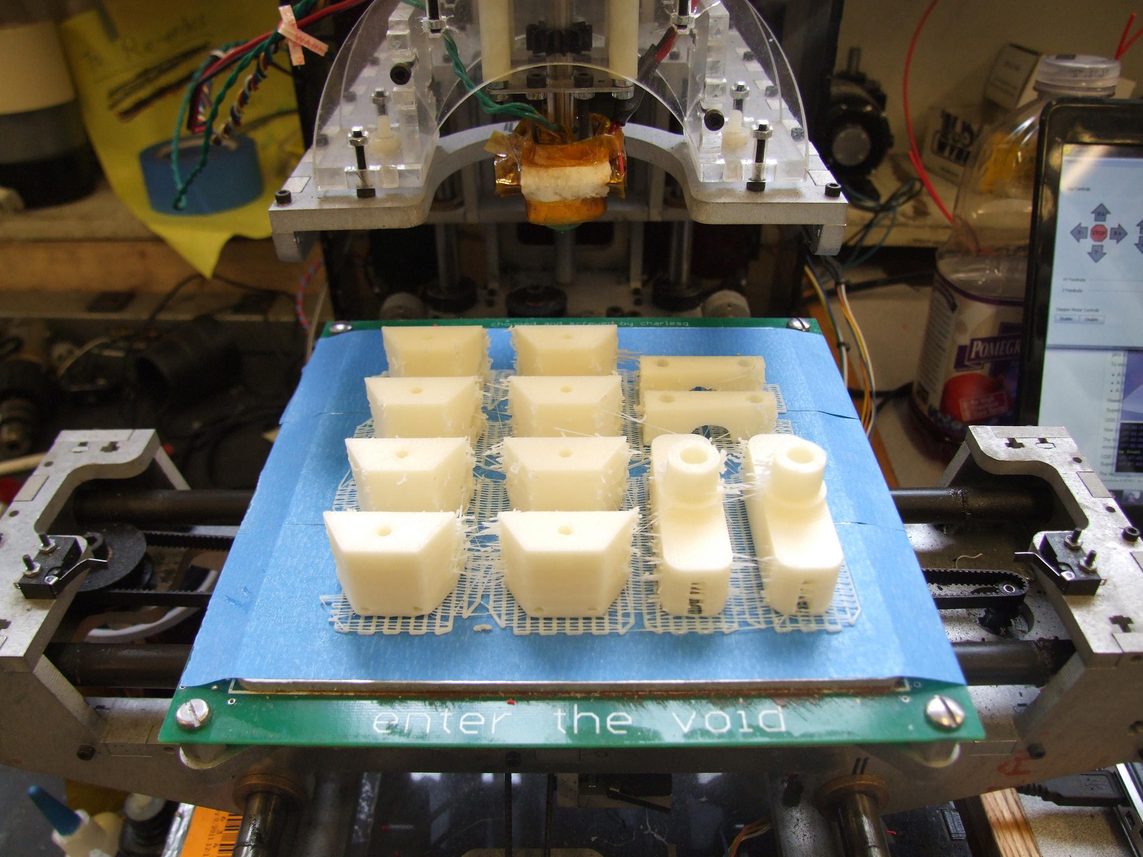
The joists can all be 3d printed Live From MITERS. In fact, I just got a new 5 pound roll of ABS plastic, and if there’s 5 pounds of anything that’s not hauling ass on this, something is wrong.

Here, I’ve positioned the speed controllers of choice – the Turnigy 100 amp HV, which has been my staple EV controller since forever (all the way back to the original Snuffles the First). Could it be that I’m FINALLY using it for a legitimate purpose? The total weight of everything here is about 15.5 pounds, 6 of which are in the ginormous death-lipos of certain fiery annihilation™, and another 6.5 in just the fans themselves. I think the entire rest of the thing only weighing 3 pounds is fantastic, considering if I had made this my way it would all be billet and waterjet-cut aluminum plates. This is not including wiring, switches, electronics, or gaudy lighting, so I expect the final vehicle weight to be closer to 18 pounds or so – still a 40% thrust overhead, which is more than enough.
STOP EVERYTHING.
At the continued peer pressure of A Certain Scientific Course 6 And Controls Guy (you should ask him Arduino questions), I trashed the entire design up there and started over.

That’s right: THRUST VECTORING!!!
The compelling argument was that as long as I was inserting servos into the pods to move vanes, I could just as well mount the entire fan on a pivot and move that instead. The overall part count is actually less, and it would definitely be more mechanically robust than some scrawny wooden flap pieces. This isn’t true thrust vectoring as found in fighter jets and rockets – I really only have control over 1 degree of freedom, i.e. the tangential component of the thrust as seen by the vehicle.
However, this is the essential direction for cancelling torque from the spinning rotors and controlling yaw movement directly. Furthermore, there is the potential to direct the thrust from each fan in orthogonal directions to emulate a midair omniwheel drive. It would allow decoupling of translation and rotation requirements from the fan speed, letting them only handle vehicle roll, pitch, and yaw stability. All of this amounts to a massive but still relatively simple controls problem. The inputs to the vehicle are desired planar motions (X, Y, altitude) and one rotation (about Z), and the outputs are eight commands – four fan speeds and four servo positions.
OH GOD THE SOFTWARE

The model’s a little more sophisticated now. Two things have changed: The inward cant is built into the 3d-printable trunnions, and I’ve moved the servo to the other side. No particular reason for that one…
I ran into a huge geometric headache trying to adapt inward canted fan pods to straight frame rails. So I took the cheater’s way out and superposed the translation and rotations into the fan mount itself. So now each fan is canted towards the vehicle center by 5 degrees, but the pod itself can be perpendicularly mounted.
There’s also alot less wood in this mounting scheme.

And again with the little frame connectors. This thing is starting to look like a flying Reprap or something – so many 3d printed joists! I should actually knock a few out on MaB to see if this is even sane.

I’ve extended the upper plate of the fan pod so it mounts a Turnigy controller. The controllers are spaced very closely to eachother, so hopefully that means I can keep the wiring runs short. The system should be drawing 50 amps or so per fan normally. Putting the controllers like this in the intake airstream path should contribute to their cooling – there’s not really space underneath to put them in the exhaust stream.
The total vehicle weight for this design seems to be about 4 ounces lighter than the first, mostly due to less wood. I hope this is big enough that +/- 4 ounces isn’t gonna matter.
I anticipate sticking the electronics, like the IMU, right in the center of the X, with altimeters at the long ends to take differential measurements such that the vehicle’s tilt can be factored in.

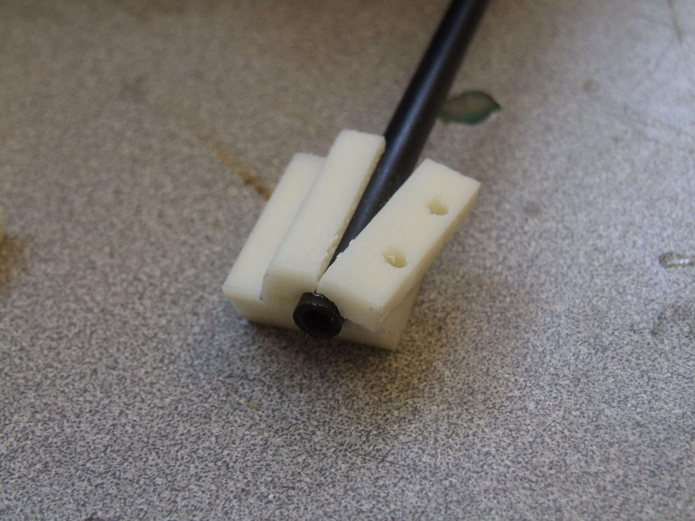
I’m confident enough in this design such that I’ve went ahead and laser-cut the structure one fan pod. It will be put together to review whether or not I have Impossible Screws, or if the 3d printed parts are going to be nontrivial. I actually caught one very important error beforehand – there was actually no way to put the fan in the pod, nor take it out afterwards. These joints are designed to be glued, and if I glue the pod together beforehand, no dimension allows admission of the fan’s flanges. And if I put the fan in first and then glue the seams… well, that’s kind of permanent. The solution was to insert little square cutouts at the edge of the hole so the fan’s flanges can be passed through.
The material is poplar plywood, commonly called “Lite ply”. The stuff’s very cheap and very flexible. And really light. It’s not quite balsa, but it’s close. It also laser cuts very quickly – I tested up to three times as fast as 1/8″ birch plywood (common material for aircraft modeling) and still had positive cuts. In fact, normal 1/8″ woodcutting speeds left a massive charred kerf. With this test fanpod as the lesson, I’ll probably cut all the rest much faster.
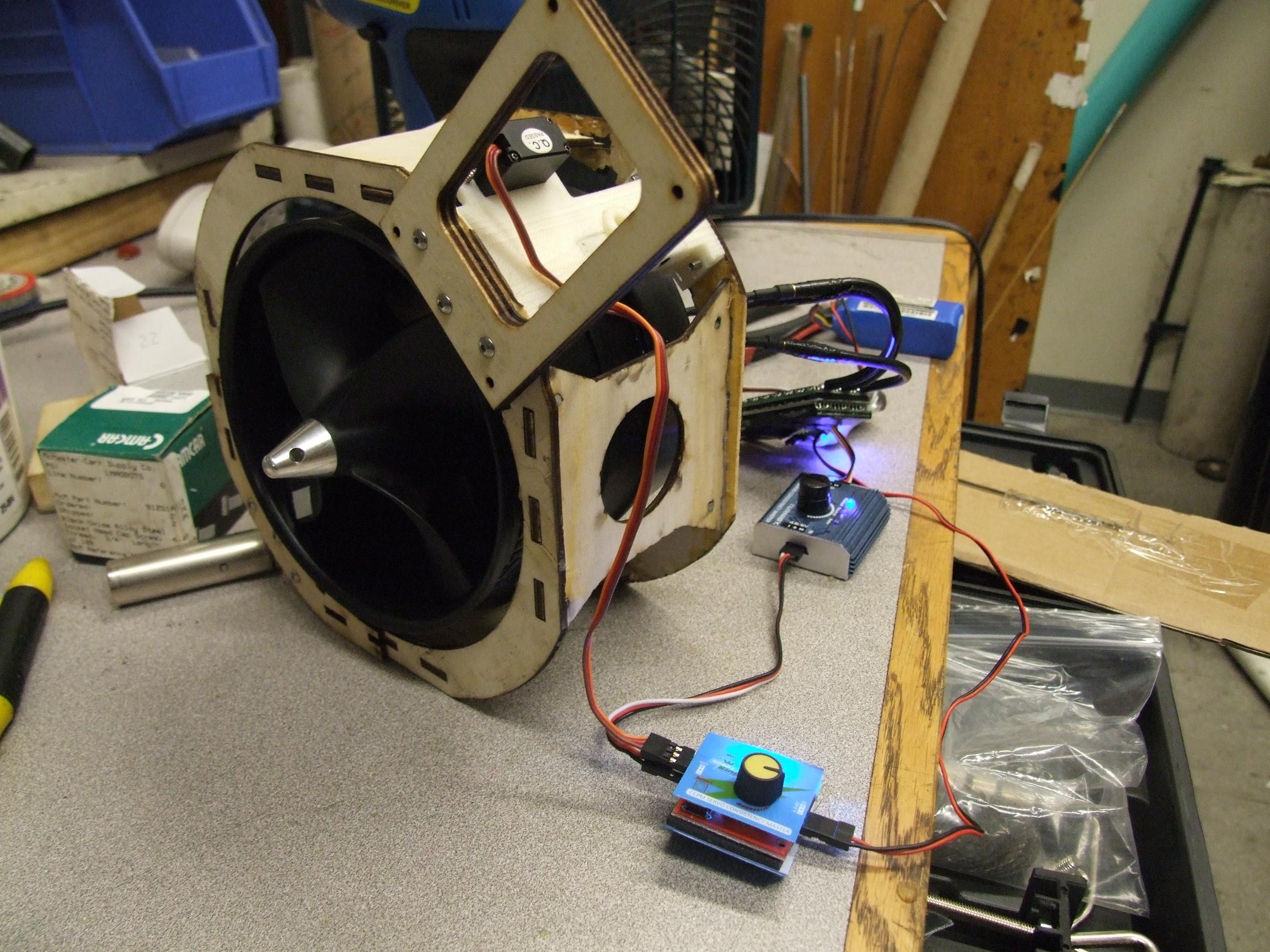
Next is to 3d print one set of fan pivots and throw together a thrust vectoring rig using Chuckranoplan‘s servos. I should be able to thrust test this thing soon.

did someone say flying reprap?