The thrust vectoring module seen in the previous update has become a working object. So what I have now can potentially be turned into a midair single axis Segway, but I don’t think it quite works like that. This module has been a physical refinement of the construction process – I’ve already made several changes and additions to the design which will be reflected in the rest of the modules. This one probably won’t make it onto the vehicle itself given its role as the guinea pig of the experiment.

The loose cage has now been assembled. Because the gaps here are so large from experimenting with laser cutter kerf, I used massive puddles of wood flour filled epoxy to assemble the joints. Most of them are filleted in addition to have epoxy between surfaces, and I clamped the entire thing down for a day (read: pile a large lead acid battery on top of) so it could set properly. The result is quite stiff, except at the corners where there is only 1/8″ lite plywood. It’s quite flexible there, and in the interest of not making a quadrotor with the torsional rigidity of thin sheets of plywood, I made an additional “corner thickener” for the outer corner which will bear the load of the frame tubes through those sidewalls. It’s attached through thick CA glue.
Next, notice that I’ve made a new controller mount. That flange is simply too floppy for me to want to mount anything to it, so that part will be “supplemented” with the 1/4″ thick part behind the cage. It will bolt through the 1/8″ wood and into the trunions below.
The rest of the modules will be built with the extra corner thickener and the bigger controller mount.
Those little plastic blocks to the left were made by my ever hard-working but rarely mentioned 3d printer:
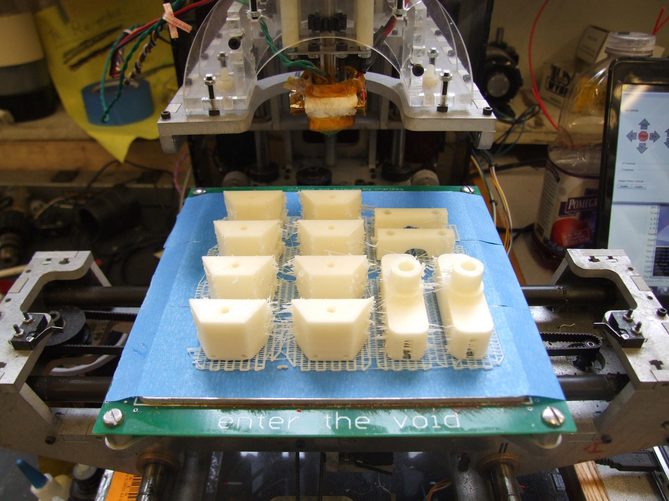
Pictured are all the frame joiners, the pivot for the EDFs, and the smaller half of each trunion. MaB is sort of my unsung hero project – making alot of things easier, but always just kind of working so I never write anything about it. Unlike my other crap which breaks every time I think about staring at it wrong.

After cleaning the little nubs off with some selective sanding and knifing, the parts are ready for use.
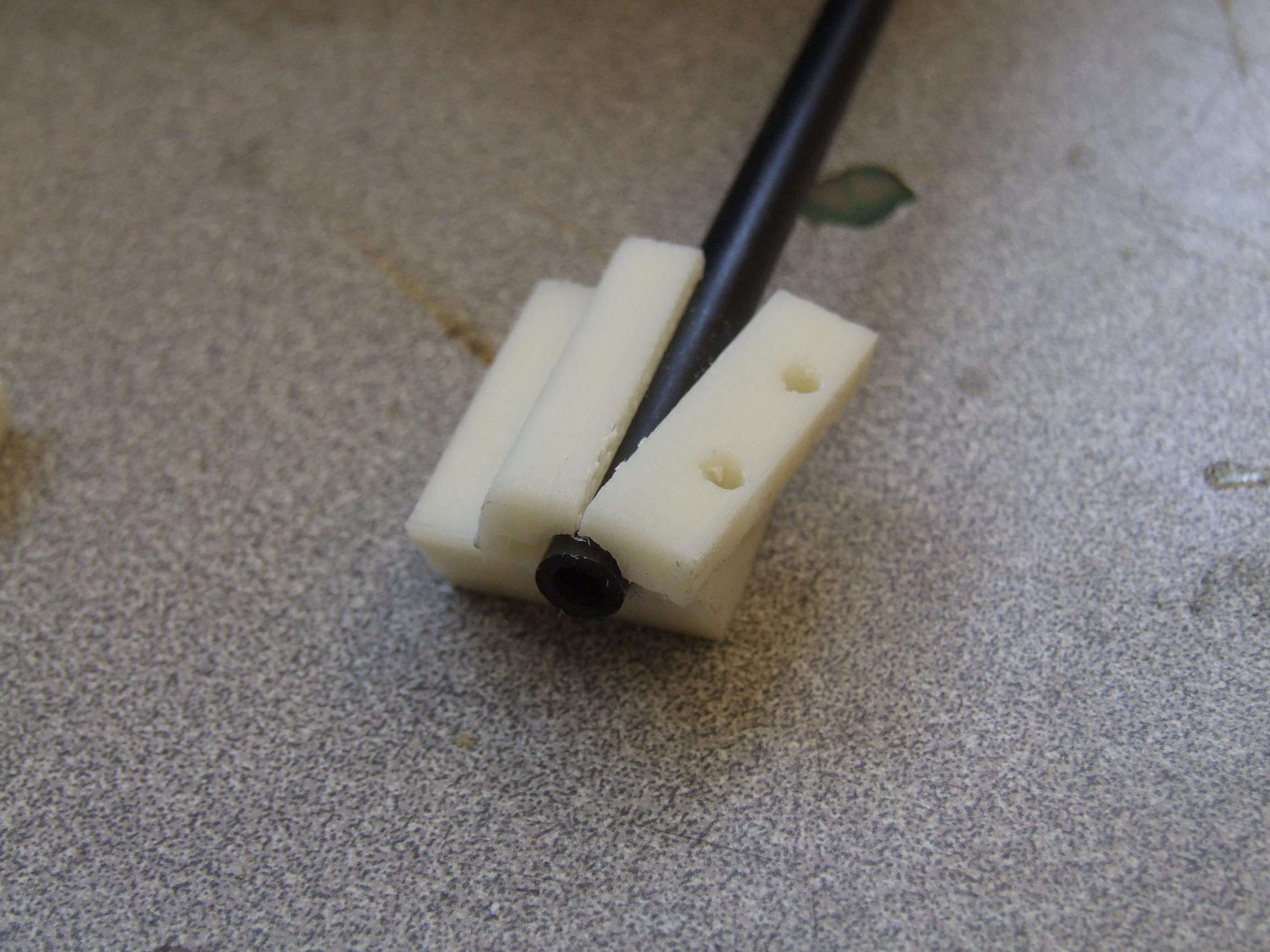
Now, I don’t trust a 1/2″ nub of plastic with holding back 28,000 RPMs of ducted fan, so those nubs have center holes that reach almost all the way to the fan flange so I can glue something in which has meaningful shear strength – like chunks of the carbon fiber frame tubes.

I also printed off this cute little tailcone for the motor. It has 1mm walls and is vented so the motor can still flow cooling air through the center. Not having a blunt edge at the back will probably gain me back another ounce of thrust or something.

Here’s the servo linkage all hooked up. I actually reprinted one of the pivots to have a built in servo horn of sorts so I could use my stock of ball links. This arrangement worked well. The 2-56 threaded rod link allows me to fine tune the angle of the fan with respect to servo neutral.
(You know you’re in the future when you can say “I reprinted it and…”)
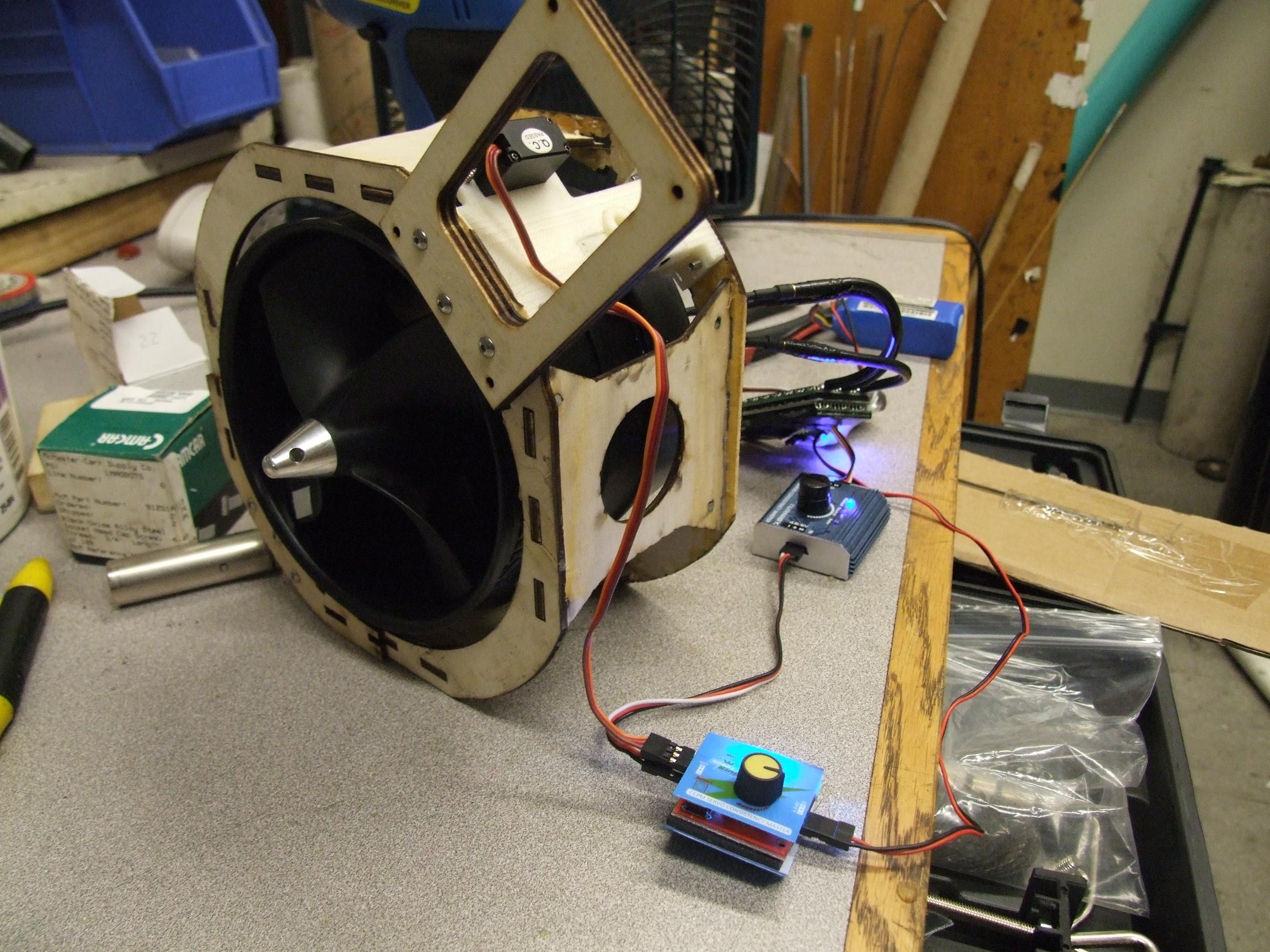
Here’s the rig readied for testing with the Controller Mounting Extension attached. The board bolting into the fan trunions is much stiffer than a chunk of wood hanging off of the main structure, and it also makes for more economical laser cutting since a huge tab like that doesn’t tesselate well at all.
Downside of printing with light fill to make things print quickly: They’re not structural really, at all. I think this was on 25% fill or something, but it exploded as soon as I applied meaningful bolt tension. I’ll clearly be doing these small parts in near-solid.
Here’s a short test video with me running the fan on 3S lipos…and a very discharged lipo at that. So there were maybe 10 volts going into this thing, period. It was still enough to shuffle the thing across a table with a 20AH lead acid battery on top of it.
There you have it. I have yet to do a full power test on 10S lipos, but that needs to happen in order for me to see if the cage is structural enough…and if the servo can even wrestle the fan around at those speeds.
Oh yeah, here’s the biggest lipo I’ve ever seen. Seriously, how did this not set the plane on fire again?

I really dig the thrust vectoring.
Nice, it seems to have a relatively fast response time considering the inertia of that EDF unit. Also, I was looking through a couple past posts and i noticed that you had plans for LOLriokart’s differential lying on the table in a few pictures. I was wondering if you could share those plans in a PDF or if you could point me to where i might get them.
That’s because it’s running at most 25% speed in the video. I am really curious as to how it will behave when the fans are going full bore.
Not to be pushy or anything but if you could respond to my inquiry about the differential i would be grateful. I’m working on building an electric goKart myself and I would like to avoid a fixed rear axle. I’m glad that as a freshman my highschool has a metal shop. It’s ok if you don’t feel like giving out the diagrams but if you could say yes or no that would be great.