The January Bot: Project Cold Arbor

Since the beginning of televised robotic sports history, combat robot builders have been repeatedly asked by fans, enthusiastic onlookers, and bright-eyed newbies, a variant of the following question:

D00D WHY DON’T YOU PUT LIKE A BUZZSAW OR SOMETHING ON YOURE ROBBOT SO YOU CAN LIKE CUT RIGHT THRU THE OTHER GUY AND SHIAT????

Good question. Why haven’t we? Sawbots are conspicuously missing from the combat robot hall of fame. Everybody wants to see them, but there have been comparatively few saw weapons built in all of the history of robot combat, and even fewer ones which actually achieved its end goals. Minion, the most famous saw-wielding Battlebot, replaced that weapon with a kinetic energy disk starting in Season 3.

So why is this the case? Saws need a delicate balance of torque and speed actually cut something. Too much of one or the other, and you either blunt off the teeth or jam it in the opponent. Essentially all saw weapons to date have been directly driven or geared very fast from a (comparatively) low-torque electric motor. That means they can scrape and spark nicely, but actually laying into an opponent will stall the blade.

The other element missing is controllable pressure. It’s difficult to cut consistently in the same place on something that’s flailing around or moving. A saw that sticks out the front of a robot but is otherwise fixed has no control over how quickly it can advance teeth through opposition armor. If it’s simply jammed into the opponent, then the torque required to actually crank the blade teeth through the material becomes phenomenal. Most saw weapons extant today rely on the stored kinetic energy in the saw to deal out damage.

This particular aspect was what inspired me to think about the Sawbot Conundrum when I was watching old episodes of Robot Wars featuring the house robot Dead Metal. Observe how effective the saw is on Dead Metal from the 2 minute mark onwards here. Dead Metal works because it is able to trap the smaller robot in its pincer jaws so they can’t move. The saw also advances on a linkage at a modest pace and has plenty of horsepower to back it up. It can actually cut things.

I immediately wondered if I could replicate the function in a smaller class, say, 30 pounds. Control of the opponent is the dominant trait of Überclocker, but it doesn’t really have a means of doing… well, anything else. I wanted a complementary Überclocker which trades off some of the control for more ownage.
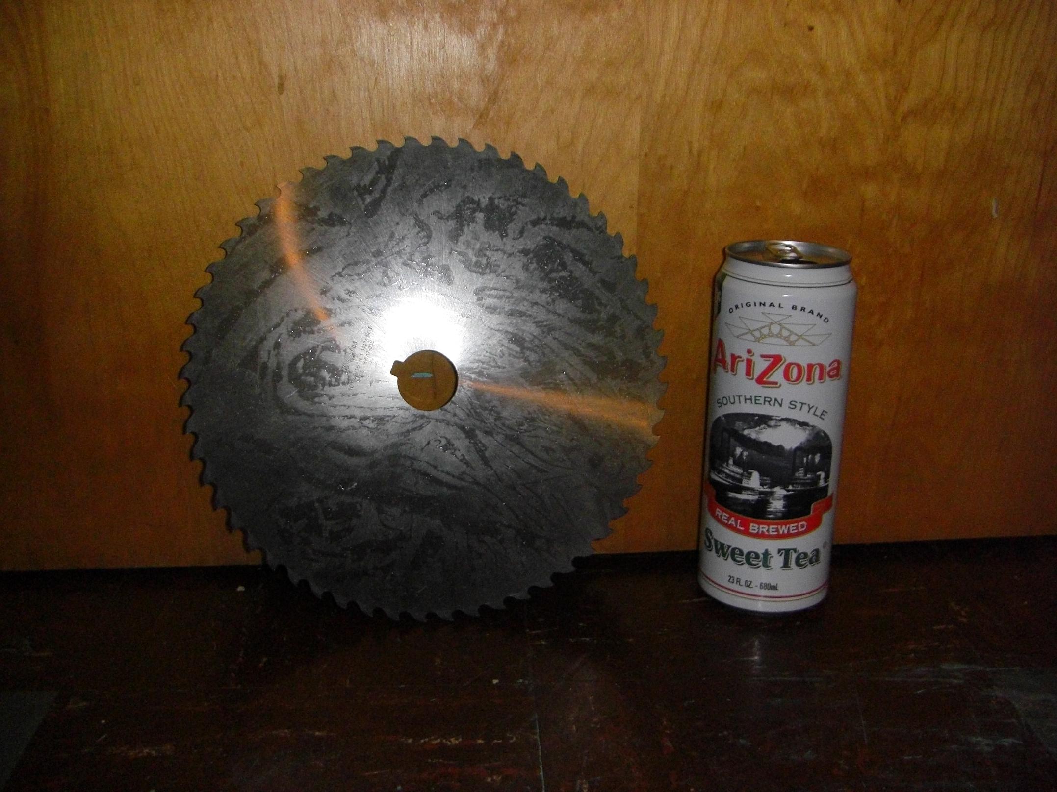
In an alignment of mechanical planets, I was swiping some more slitting saws for MITERS off Ebay when this mutant blade showed up in the listings. I didn’t even know they made “slitting saws” this large. It’s a 10 inch blade, 3/16″ thick, and weighs a solid 4 pounds. The bore is 1.25″ and keyed.

Now I was practically obligated to build a robot around it.

To drive a saw this large would require immense torque. I investigated planetary and spur gear reductions before deciding that neither could satisfy the torque transmission requirement, be minimal in weight (spur gears were totally outclassed here) and also be easy to build or cheap to buy (there go all planetary gearboxes in existence).

Luckily, I remembered that I had…
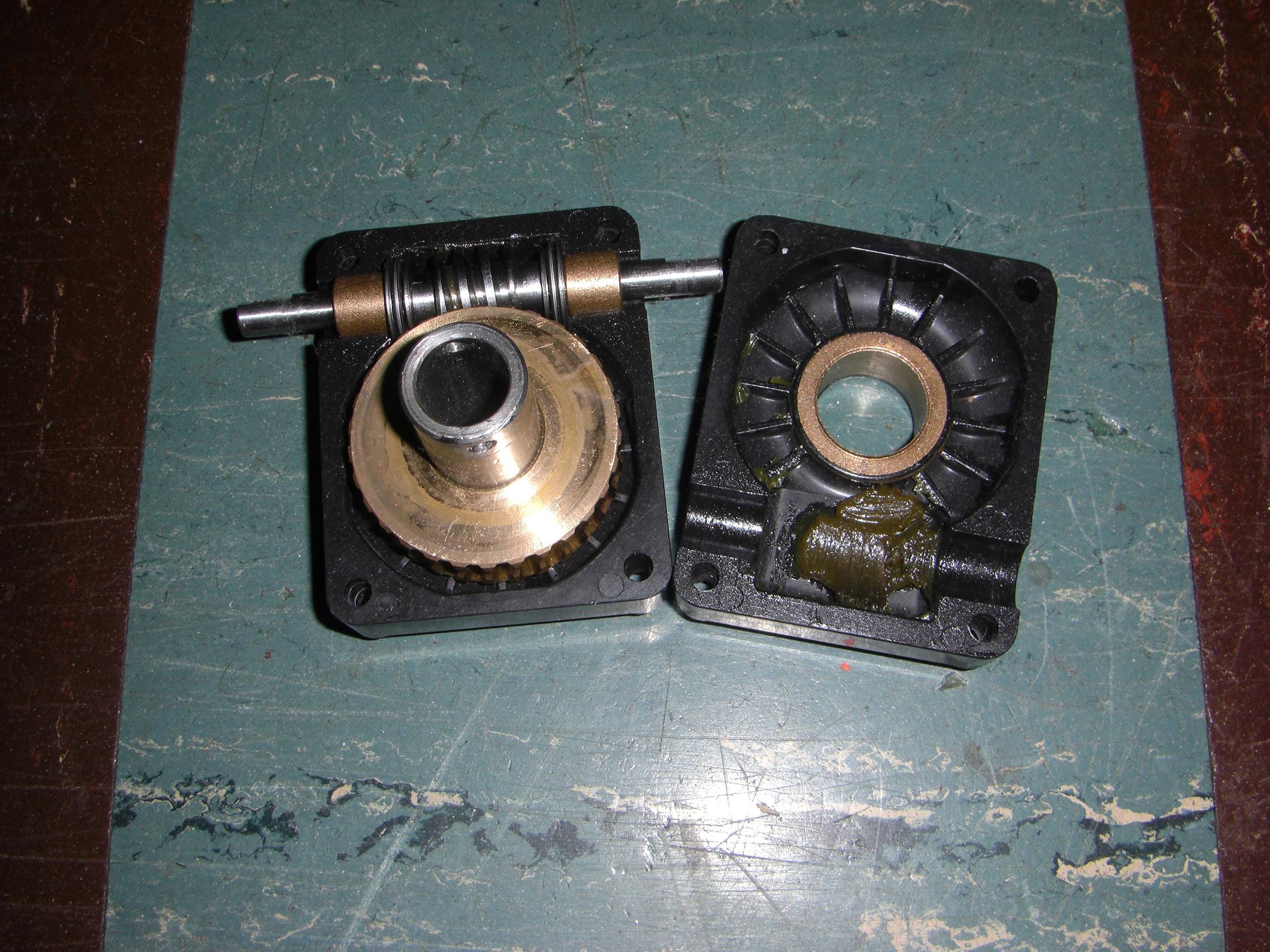
…this worm gearbox that I scrounged out of a pile of discarded lab cleanup materials. It came of the base of a nicely waterjetted and assembled robot arm that looks like something heavy ran into it – or, more likely, it ran into something heavy. Either way – free 30:1, 12 (ish?) pitch single-enveloping worm gear.

While worm gears are notoriously inefficient, it’s much easier (in today’s world of brushless one-upsmanship) to dramatically over-motor a weapon to compensate for that. Worm gearboxes are probably the most common things in industry, also, because of their simplicity, compactness, and durability. If you don’t mind the less-than-peak efficiency – which \m/assive \m/etal generally doesn’t – then why bother with something else?

There do exist machine tools which use worm gear driven circular saw blades to cut metal, generally competing with bandsaws in situations where edge finish and accuracy are important.

They are known as cold saws, named for the fact that they use a toothed steel blade to generate chips of material instead of a disc of abrasive rotating at high speeds. I like them better than bandsaws, because I can hang off the handle on the largest cold saw in the shops and take down a 4″ solid round of steel in under 30 seconds, and that’s just too awesome.

Thus the inspiration for Cold Arbor was complete. The name is both a play on cold saw and the Battle of Cold Harbor, one of the “bloodiest, most lopsided battles” of the American Civil War.

Anyways, I love my found object gearset, but that janky plastic case has to go. Why put such nice gears in a plastic case?

Oh, right – nobody is expecting me to hang a 10 inch sawblade off one. Using the existing mounting dimensions, I designed this preliminary gearbox case, to be made of aluminum. Some 7/8″ bore ball bearings will take the place of the bronze bushings. Since the shaft is hollow, a large bolt running through the center makes for easy blade mounting.
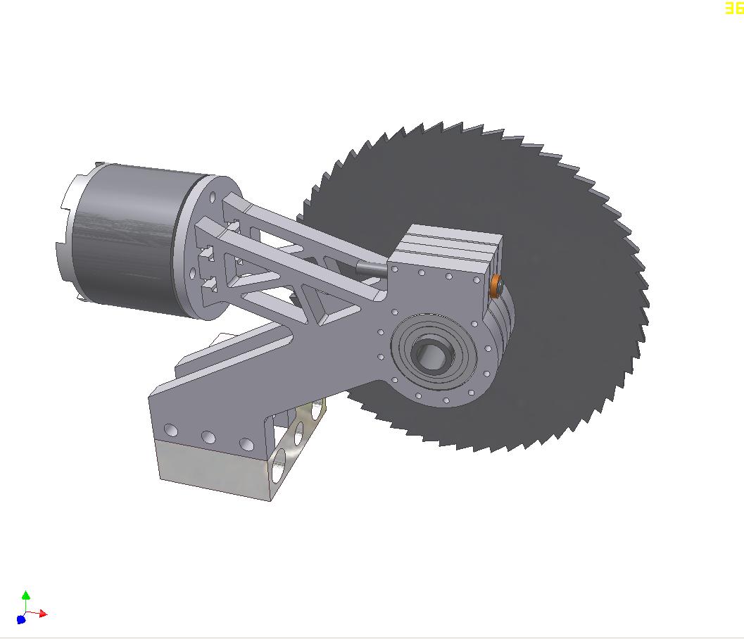
So here’s the first try at the actual blade assembly. This is more inspired by a sliding compound miter saw. The premise here is to reach the blade as far into an opponent as possible. Using a plain swinging saw, the maximum “cut depth”, so to speak, is limited to the saw radius minus the radius of the gearbox. This design was an attempt to remedy that by allowing the saw to “reach” further by sliding.
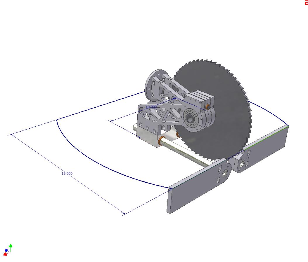
The prelim design more progressed, showing the prospective linear bearing rails. This was about as far as the design ever got before I realized it was going to weigh far too much, and would suffer from stiffness issues. So that was scrapped.

The truncated circle floorplan begins to make a return here.
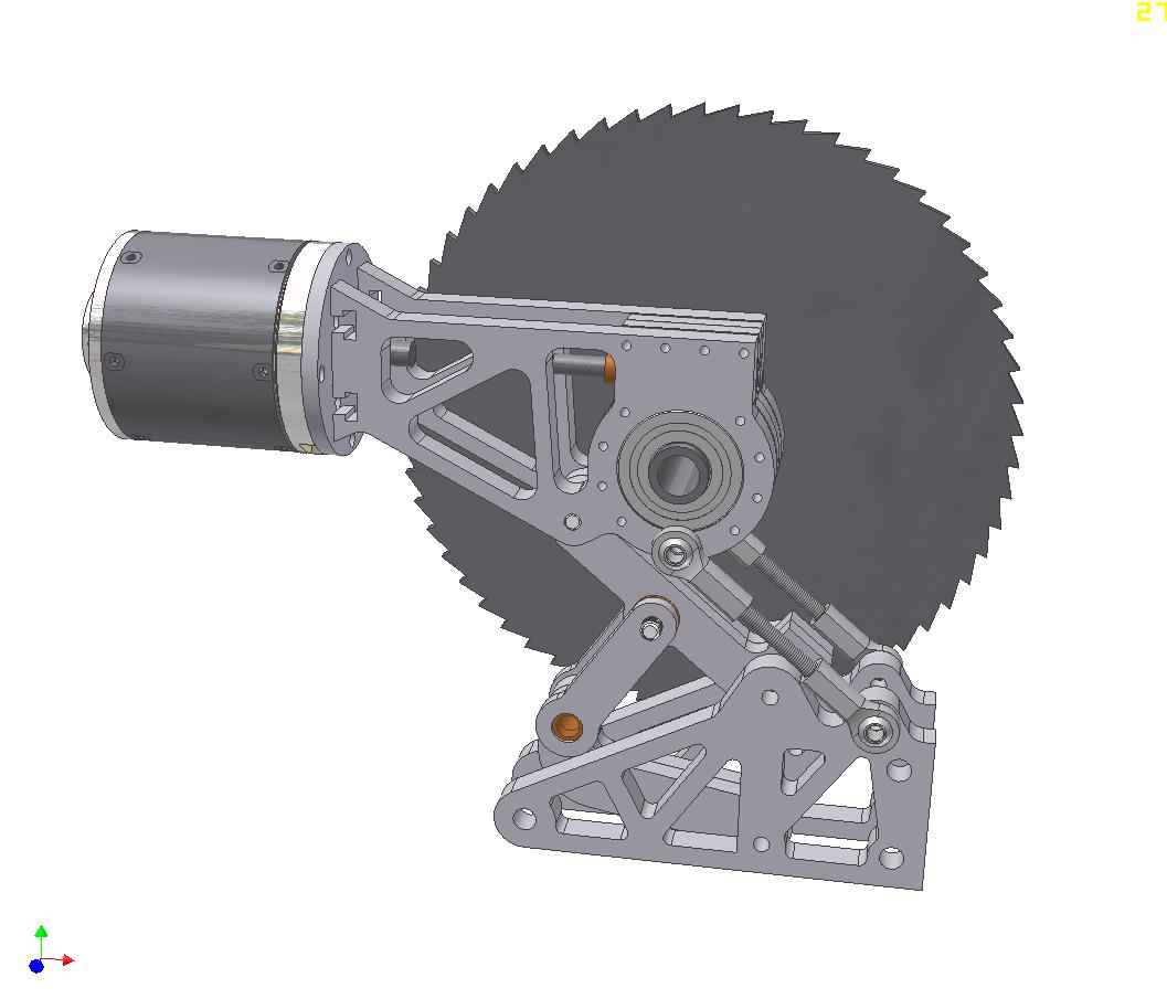
Crazy design number 2 uses a six bar(!) linkage that allows the saw to retract fully into the footprint of the robot, but extend about 6 inches forward. The swinging motion bring the saw over, then down upon the opponent. The whole thing would be moved by 1 actuator, mounted at the bronze bushing and causing that part of the linkage to move about 70 degrees.  The motor would remain parallel to the ground at all time.

A much more practical idea than the sliding design, but ultimately, it also faced some pretty hefty weight issues, especially after I designed in the actuator.
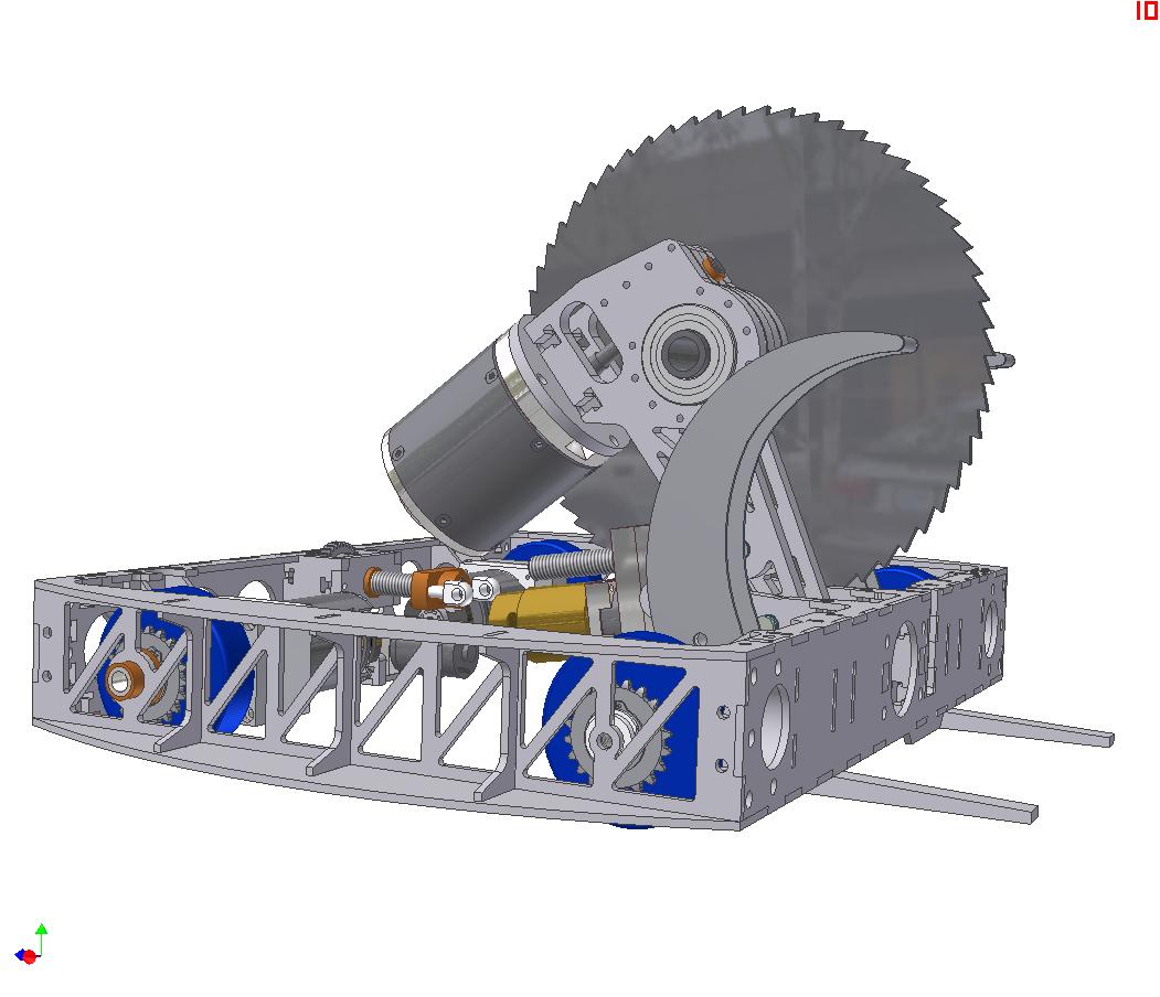
Alright, big leap of faith here. What the crunk is going on?

I decided to give up on a cool swinging linkage and just made  a conventional linear actuated pivoting assembly. This linkage swings through just over 75 degrees of motion to bring the saw all the way to the ground in front of the robot.

The motor mount is integrated into the body of the gearbox to make it easy.

One additional component visible here is the actuator for the clamp. Both clamps are connected to the single linear actuator at the rear, so they should move (sort of) together. They are linked to the actuator nut with a ball-jointed tie rod.
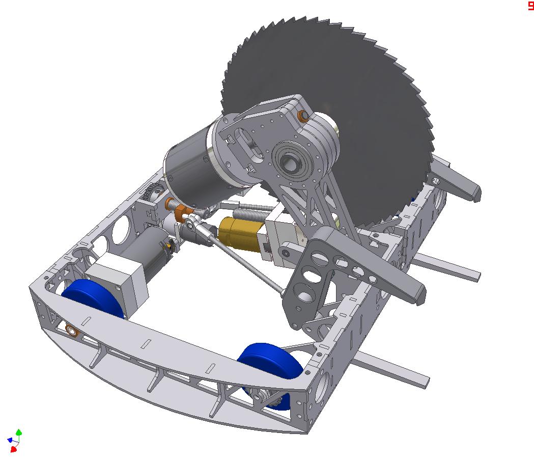
A clearer shot of the clamp actuation. Notice the top claws have been replaced with a fancy to-be-welded structure.

While the claws actuate together, both clamps (top and bottom of each side) are capable of independent swinging motion. This should allow me a bit more flexibility in approaching opponents.
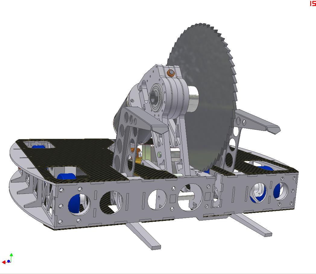
A bit more progressed now. Top and bottom cover plates will be the usual order of 1/16″ Garolite reinforced in select locations.
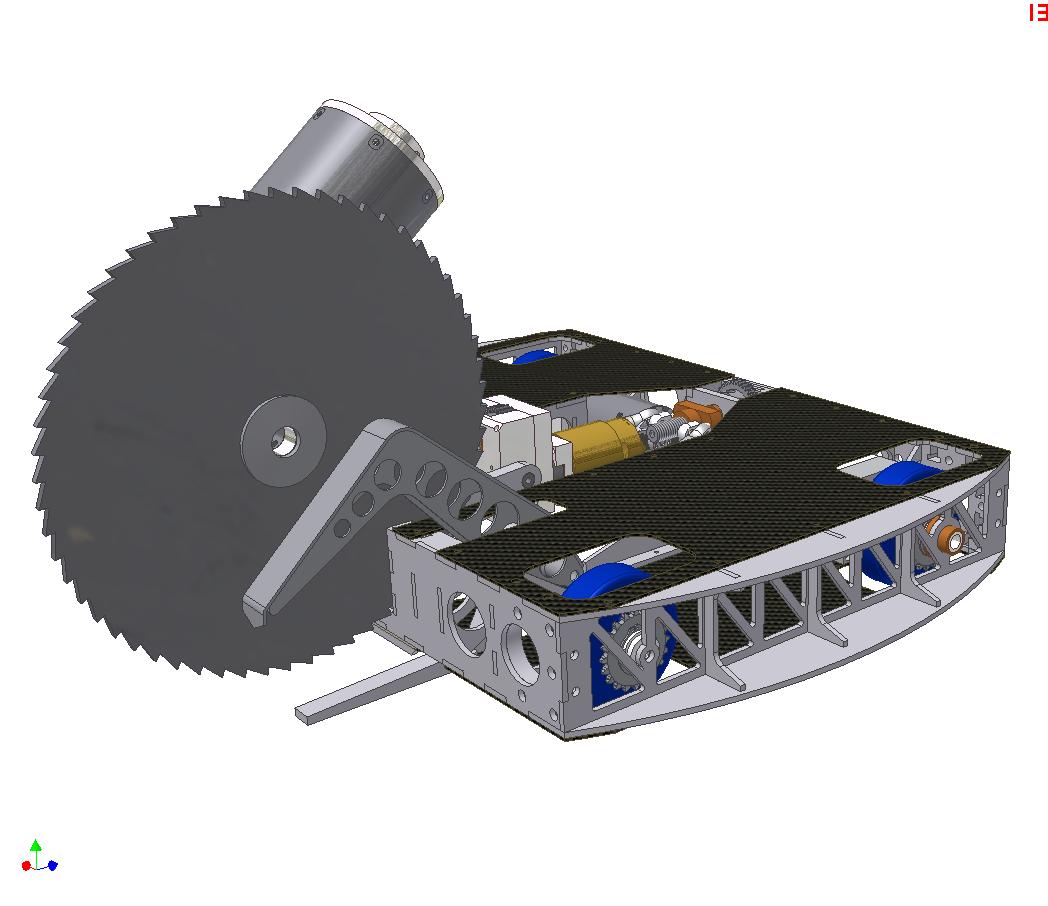
The saw in full deployed position. The bot can actually reach far enough to cut itself. To prevent this from happening, the leadscrew length in the actuator will be tuned appropriately.
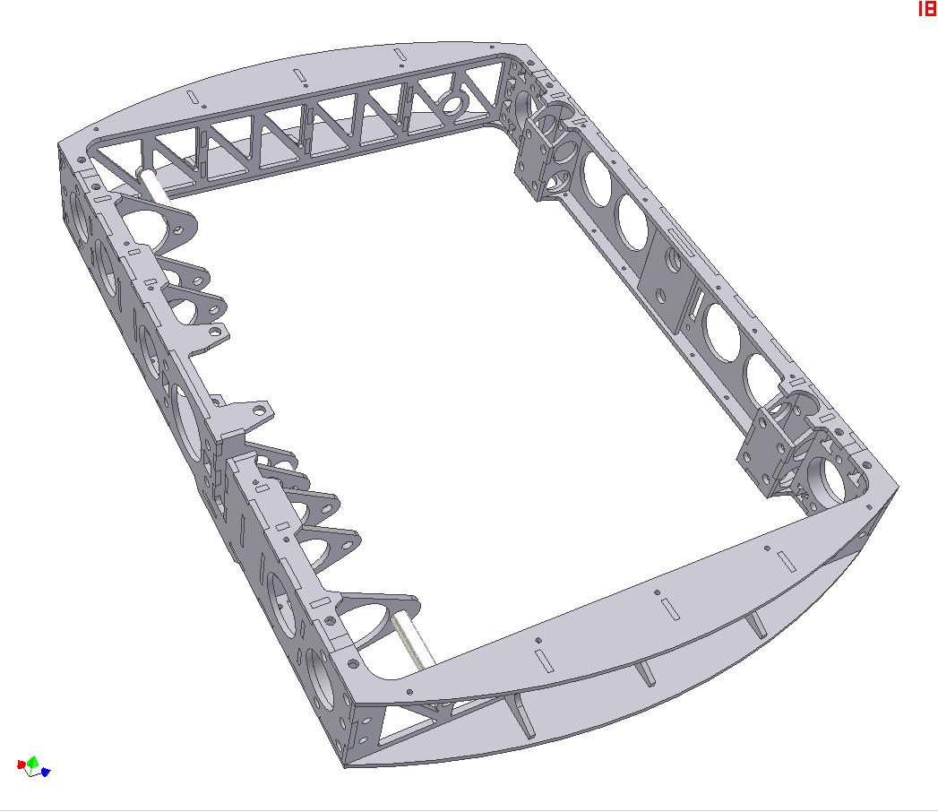
The frame of the bot will be sort of a unique first try for me. It will either be zinc-aluminum brazed or, with luck, be legitimately TIG welded. Either way, my first foray into “permanent joinery”, so to speak. We’ll see how it turns out. The robot just didn’t have the space to put T-nuts int the frame.

The frame is four pieces – front, back, and the two sides.

Filling out the internals a bit using AUTODESK INVENTOR 2010!!!! on my NEW LAPTOP!!!!. The fancy welded flaw is gone – I figured four fancy welded assemblies were enough for a first shot. They have been replaced by a single flat aluminum top claw. Less rigid, but also easier to make and assemble.

I plan to let this bot use the same batteries as Überclocker, since I already have packs made. 7S A123 cells yields about 23 volts nominal and 25 volts peak, which is roughly the tolerance level of the Victor 883 controllers anyway. I have leftover 883s and 884s from Clocker.

Electronics will be mounted on “cards” in the body. Not really for quick access and removal, but there wasn’t a way to mount everything horizontally.
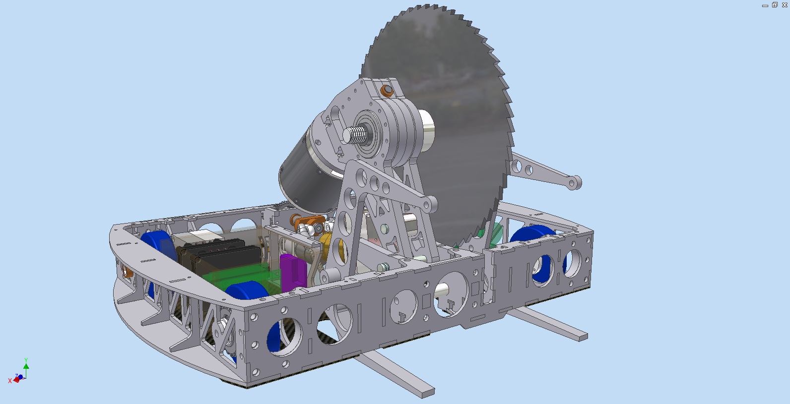
A beauty shot of everything so far.

I discovered the animation module of Inventor and briefly played around with it. Here’s a cool CAD video of the robot mechanisms in action.

The schedule for completion is “ultra fast-track”. I managed to put together most of Clocker in two weeks, so this robot should be no different. Let’s hope I’m right.

HERE WE GOOOOOOOOOOOOOOOOOOOOOOOOOOOOOOOOOOOOOOO

Übercløcker RЭmiχ RЭvived, and SEGFAULT Update 2

In the last Überclocker-related post, I said

this conversion ought to go quickly since I’ve already drilled the new mounting holes to accommodate them.

By this I meant ”

this conversion ought to go quickly since I’ve already drilled the new mounting holes but am swamped with classes, other duties, and a lack of motivation to do anything robot-related so Überclocker has been sitting on a table at MITERS taking up work space for two months

But that’s over now. I charged the Mental Capacitor of Project Motivating (+1) enough to go take apart the drivetrain to stuff the DeWalt motors in. The whole operation actually took about 30 minutes total, by the way, it’s just that the time constant of the MCPM is a semester or so.

Here’s a picture of the robot.

I excavated the carcass of Test Bot SP1 to use as a chew toy for testing ‘clocker. There’s no test video, unfortunately.

I can’t exactly describe the new drivetrain as “Fast”. In fact, I think the HTI motors resulted in an overall higher speed, but not by much. Calculations put the anticipated top speed around 8 to 9 miles per hour. The bot isn’t slow by any means, but it was almost too controllable. I like a bit of unpredictability in robot handling.

For future events, I might consider recutting the intermediate drive gears to act as a speed increaser. 8MPH is nice for small arenas and stages like Dragon*Con, but in a larger arena it is a handicap.

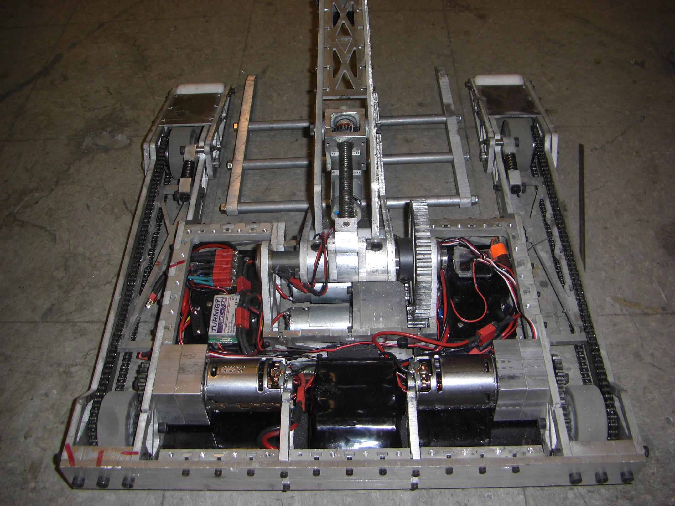
Here’s an overall picture of the robot internals, now featuring DeWalt drill motors mated to undoubtedly overdriven Harbor Freight drill gearbox parts.

Segfault

Alright, so I’m pretty damn sure the project is moving forward now, considering I just dropped big Benjamins on aluminum plates. The project has actually been limbo for a while because I’ve been slammed with everything else that does not pertain to building. As the assignments-and-papers season winds down and OH-GOD-EXAMS-AND-FINAL-PROJECTS season begins, there’s an occasional moment where I can… you know, do other stuff.

I’m also in luck because I have no classes this term which have final exams.

In the last SEGFAULT episode, we left off with a picture of two wheels.

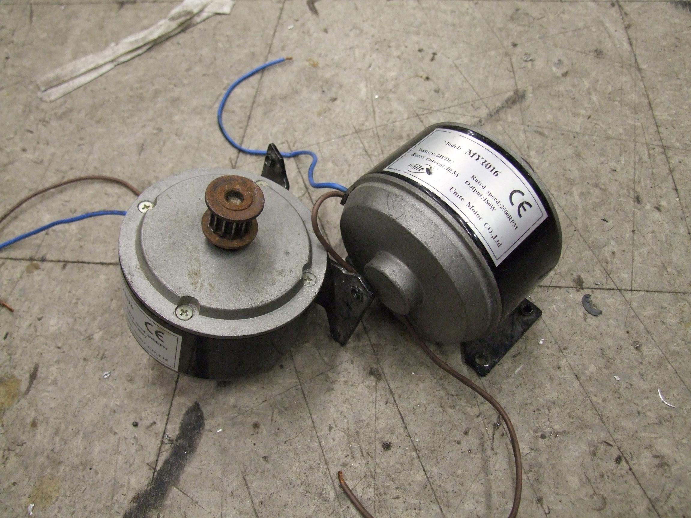
Like before, not exciting at all. Through some more excavation of the archaeological site that is MITERS, I sequestered these 180 watt DC scooter motors, which seemed to have been paired with the wheels at one point in time. They have matching pulley pitches.

The pulleys gave a speed reduction of roughly 6 to 1. Through some crafty mathematics, I backsolved the specs of the motors so I can actually play some numbers games.

The manufacturer, Unite Motor, was kind enough to give some measurements of torque and current for these motors. Real measured numbers are better than theoretical ones, and leaps better than bullshit such as “TURNS” and “WINDS”.  The rated torque (Tr) and rated current (Ir) were 0.7 N-m and 10.6 A, respectively.

This was nice because if you have torque and amps, you can immediately get a critical constant of the DC motor, the torque constant (Kt). The Kt of this motor , Tr/Ir,  is 0.66 Nm / A.

This alone doesn’t tell me much, because I don’t know what the maximum torque of the motor is if I don’t know how many amps it can ultimately pull if stalled. This is not provided by Unite Motor, shame on them.

But fortunately, they also gave a rated speed specification, which occurs (I hope to Robot Jesus on a stick, anyway) at the same point they rated Tr and Ir. This rotational velocity ω at the rated input voltage Vin of 24 volts is 2,600 RPM, or 272.3 radians (rad) per second.

In an ideal motor, power in equals power out. Power is torque (T) * speed(ω) AND also volts (V)* amps(I). Therefore, the crafty relation T/I = ω/V occurs.

Hey, this is convenient, because what it’s saying is that in SI units, torque per amp IS speed per volt. The motor back-EMF constant, Kv, is equal to Kt. So this motor as an ideal model gets 0.66V / rad / s. This is to say that if you turned the motor at 1 radian per second, it would generate 0.66 volts for you. Conversely, running the motor at 0.66 volts will make it turn 1 radian per second. Kv = Kt only works in metricland, by the way.

But real motors aren’t ideal transducers. They have resistance in the windings that turns input power into heat. A real motor can be modeled as a resistor in series with the ideal motor. The resistor drops some voltage across it while the motor is under load, so the ideal motor sees some value below your input voltage.

Luckily, I know that the motor is rated for 24 volts Vin while turning 2,600 RPM or 272.3 rad/s and having a BEMF contstant of 0.66 V/rad/s. This means the voltage the motor is generating by virtue of turning, Vbemf = 272.3 rad/s * 0.66 V/rad/s = 17.97v.

Even better is that this is known to happen while Ir amps are flowing through the windings.  When you have the differential voltage across a resistance and the current flowing through it, you know the resistance R through Ohm’s Law.

So the motor resistance Rm is simple (Vin – Vbemf) / Ir = 0.56Ω.

Now the stall characteristics of the motor can be calculated. When the motor is stalled balls to the wall, Vbemf = 0 because there is no rotation. Rm dissipates all the power you put into the motor, and the only current flowing is therefore Istall.  Through Istall = Vin/Rm I know that the motor will pull a maximum of 42 amps. Then smoke. At 42 amps, the motor can make about 2.75 N-m of torque.

The no-load speed of the motor ideally occurs when the input current approaches 0. In practice this never happens because of Rm, but the NL speed is something that has to be measured. I can only conjecture on how fast the motor will turn with no load by ωnl = Vin * Kv, and assume the motor current to be something small. This usually gets you within 10% or something. The guessed no load speed of these motors is around 345 rad/s, or about 3300 RPM.

Okay, enough DC motor theory.  So now I wanted to find out what the limit is in terms of speed and tilt angle if I used these motors and their matching wheels.

Here’s a (really, really) rough model of me on a balancing vehicle. Segway-type vehicles are a variant of the inverted pendulum, a classical problem in control theory and physics. The actual equations of motion for such a system are a bit convoluted, though rest assured I have been forced at chalkpoint to derive them step by step.

I just want a ballpark number for how fast I can go, so I can gauge the type of helmet I need to prevent too much brain splatter when I fall over. This can be easily approximated in the above system, where you have a point mass approximation of me, tilted out in front of the vehicle by an angle Φ, and away from the center of rotation by a distance d. d is the distance that my center of mass is above the vehicle platform. In a typical human, the CoM / CoG occurs a bit above the hips. I assumed this was 1 meter for sake of argument, since I’m not that tall and this is not very scientific. The vehicle itself is assumed to have no mass yet. This is a very bad thing to assume, and strictly limits this to guessing “steady state” characteristics – i.e. no acceleration of any kind is allowed.

In classic 8.01 fashion, the goal is to keep me-in-a-black-hole from acclerating. That means all forces and torques have to be balanced.

Φ is referenced from the vertical, so the Condensed Matter Charles Equivalent Force Diagram™ is thus. N is provided by the ground – we are assuming I’m on solid ground here, not flying, so the vehicle doesn’t have to generate lift. This may also be bad assumption.

That leaves just F and mg sin Φ to fight it out.  The latter is provided by me existing and also tilting the vehicle forward or backwards. F comes from the torque of the motor and the radius of the wheels: F = T/r. Therefore, mg sin Φ = T/r.

The uber-ballparked approximate steady state model of the vehicle is then given by Φ = arcsin ( T / mgr ). If I have a torque figure, I can estimate the maximum angle of tilt that the motors can sustain while moving at constant velocity. That means if I run over a pebble, it’s all over.

To avoid this scenario, I want to size T to be under half the stall torque of the motors. The reason is that Tω = VI maxes out at one half of any of the input variables. This is the point which the motors make maximum power. If I’m crusing at maximum power, there is no recovery if the unstable system deviates further from the vertical because the motors can’t exert any more torque without slowing down. Which of course will only make the situation worse.

I decided that 33% peak torque was the “safe point”. This gives me some leeway such that the motors can exert a momentary, more powerful shove to counteract my attempts at crossing the critical Φ. The real Segway does something like this – if you try to go too fast, it will start tilting back to save your ass (/face).

33% of stall torque for my two motors driving a 6:1 reduction  on 4″ radius ( 0.1m) wheels is  (2 * 2.75 N-m * 0.33 * 6) = 10.89 N-m. So that gives Φ = arcsin ( T / mgr ) of 9.6 degrees or so.

Decently smooth. 10 degrees is pretty steep for a lean angle during travel, but I was concerned with the peak torque (/force) limiting how quickly the platform could react to a sudden input like me jumping on it. If this is limited, then the whole vehicle will feel sloshy and risk not being able to recover from a sudden disturbance, like hitting a small child.

Okay, so I’m not designing to target small children (honestly!), but things like bumps in the ground, terrain changes, sidewalk seams, door and hallway thresholds, etc. all represent sources of external disturbances.

Having these numbers, I put the motors into the parts bin (i.e. LOLrioKart) and began working on vehicle design.

This is a kewl motor.

I wasn’t able to design for too long before another intrepid MITERer mentioned that he crufted some motors out of a lab cleanup.

The deal with lab cleaups here is that the proper response as an engineering student is, as soon as you receive an email containing the words “LAB CLEANUP” or similar, drop everything you are doing and immediately report to the scene to claim cool stuff. Sadly, I don’t make it to many of them, but a surprising majority of cool Reuse stuff goes to MITERS because there are so many of us that at least one person is on guard.

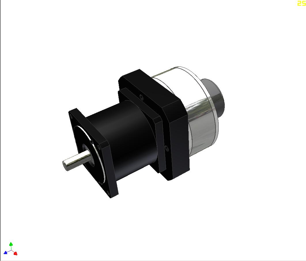
These are Kollmorgen Servodisc motors, renowned in the industry for being flat and pancakey…as well as being extremely power-dense. They are coreless motors. That means there is no big iron thing in the rotor to accelerate, and such motors can reach extremely high angular accelerations. That means they respond to commands fast.

Fast is good. Also, Kollmorgen, being a legit motor manufacturer for legit industries, completely chracterized their motors in the datasheet. Even handily providing me with armature inertia if I care to include that in the system dynamics (hint: No.)

These type U9D-E motors are attached to 10:1 precision spur gearboxen. Convenience in motor form – so I borrowed them on good faith that they won’t be baked or damaged. I sincerely hope this will remain true, because I sure as hell can’t possibly afford these motors in real life.

Running the numbers, I got that the vehicle could achieve almost 30 degrees of forward tilt. This just shot the error margin into low earth orbit, so the ‘morgs win the motor race. When the vehicle is 30 degrees off kilter, shit has gone down anyway. Or is about to go down. Hard.

With these, even if I was completely wrong on the physical modeling, I’d have enough torque capacity to tune the final system to taste.

What to do with kewl moters? Digitize them!

I like motors that are flat colors and prismatic.

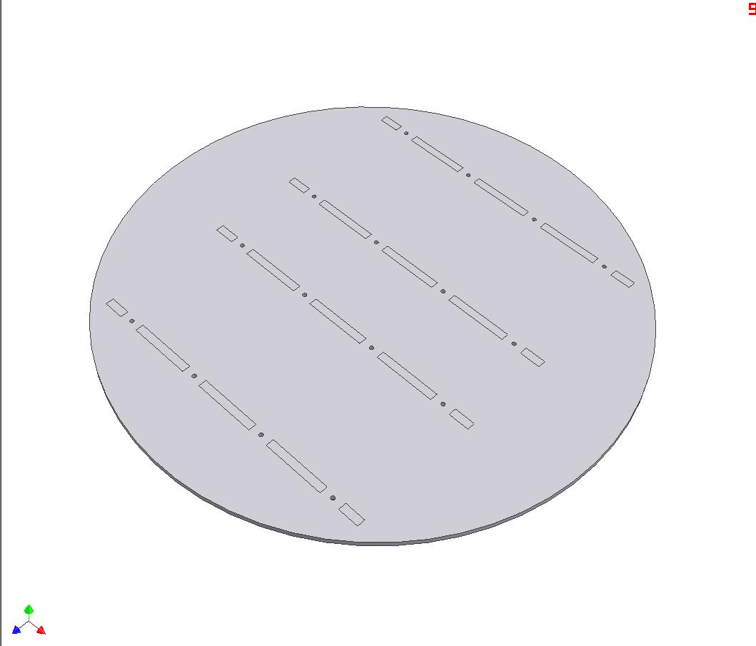
Hey, it’s a circle.

I’ve recently taken a liking to the truncated circle profile. This is clearly visible on my 2.007 robot. It’s alot less boring than just plain square sides.

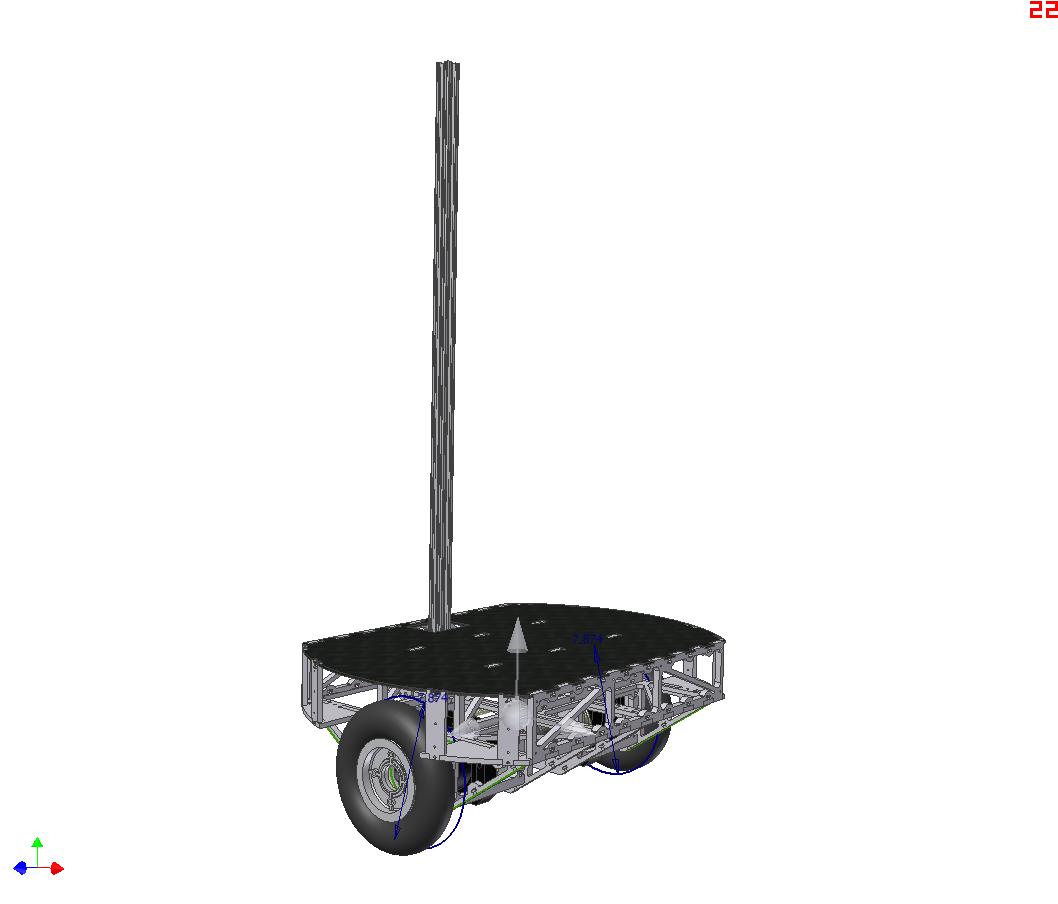
SEGFAULT is built around a 24 inch diameter circle. Having an actual 2 foot circle as a baseplate is excessive, so the ends will be clipped off.

Underside, showing the motor carriers.

The circle is cut where the motor modules end. The overall length is now around 17 inches.

…Okay, just a LITTLE LEAP OF FAITH THERE.  What the hell is that?

I skipped over more screenshots of the CAD work because it was essentially done in one night. That means it sucks and is riddled with flaws. I’m putting this here because it will probably represent the overall shape of the thing, even if details change.

The frame is all 1/4″ and 3/8″ aluminum appropriately waterjetted and T-nutted together. I’m currently on a mission to reduce the sheer amount of metal used in construction. While the whole thing (including stick AND both drive motors!) only weighs 36 pounds, it needs alot of metal. And it’s a waste of the metal, because the plates are totally trussed out and hollow.

What was that I said about it sucking and being done in one night?

The difference between this frame and essentially all the other DIY balancing vehicles is that it has tiny-ass wheels. I mostly chose this route because i already had said wheels. In order to fit components, then, I had to make an “middle deck” above the motors, where most DIYers will just put parts between the motors and under the top platform. A bit convoluted, but I don’t want to go back and redesign everything. Batteries go in the middle deck, along with most controls.

There’s nothing on the stick yet, because I haven’t gotten around to it. At most, there will be a simple panel dashboard showing battery voltage and probably speed, along with a main power switch. And handlebars.

Steering will be performed by tilting the stick left and right, so there’s no conventional grip throttle like on the first generation Segways.

Alright, enough is enough. Time to start on something – pay attention to this space. And I promise that SEGFAULT will get its own page soon!

ω