I realized I’ve accumulated almost 40 pictures over the past week or so. That’s quite a bit too long for just one build report, so I’m splitting the more recent work into two halves. The bottom line is that the robot is done.
… no, not really, but it’s close! You know, just like the last 4 or so build reports where it was “close”.
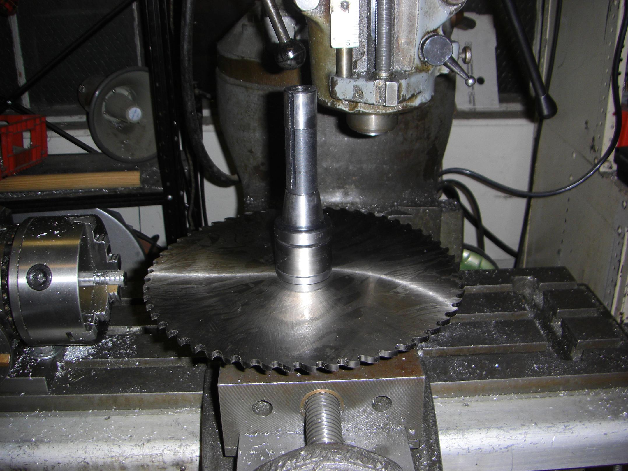
Let’s start with a picture of machine abuse.
Actually, this is just a picture of possible machine abuse. The big 10″ milling saw I bought can in fact fit on two arbors: one Cold Arbor, the other an R8 arbor for the mill.
…so, if I ever wanted to slit something serious, or just blow up the Bridgeport spindle, then I have the tool to do it with!
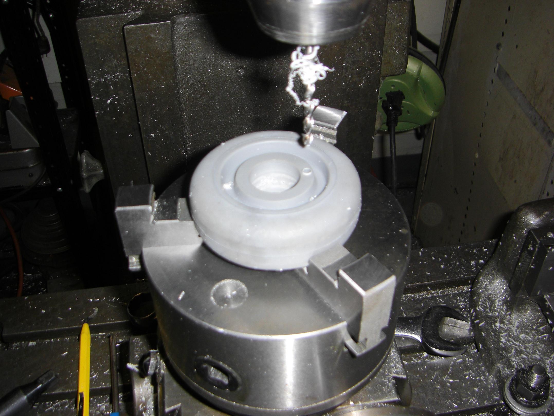
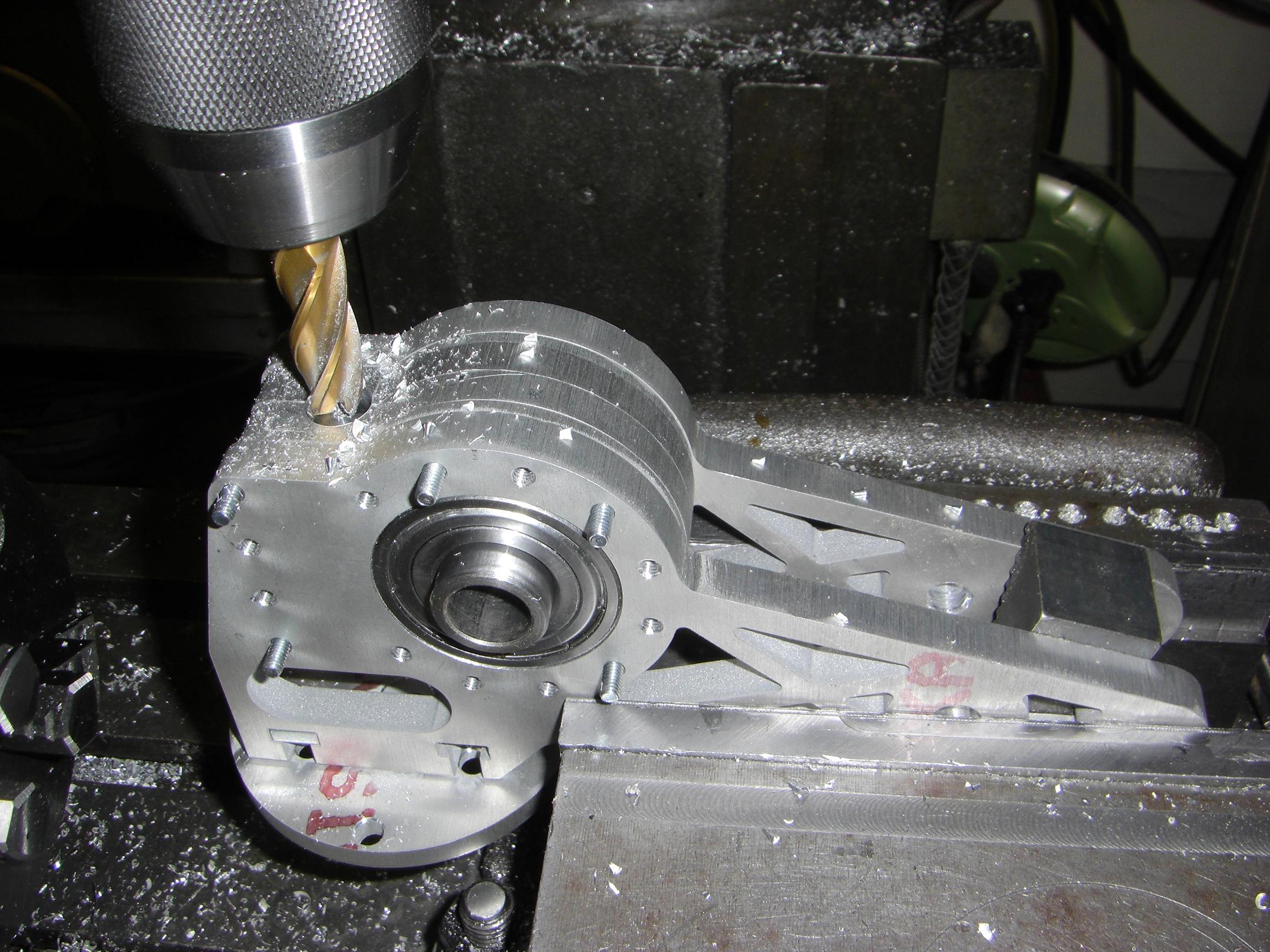
All kidding aside, let’s drill the wheels out. These have a bolt circle so they can be fastened to the hub.
I was concerned that fixturing to half of a gumball-hardness rubber wheel was going to result in it flying across the room after ricocheting off my face. But, since polypropylene machines like air, the drill did not seize or twist the wheel out of the fixture. All four wheels were done In A Jiffy.
I turned my attention to assembling some of the clamp actuator parts. The actuator is quasi-integral to the frame, so I had to perform some interesting sanding and grinding maneuvers to get the assembled structure to slip into the back frame rail.
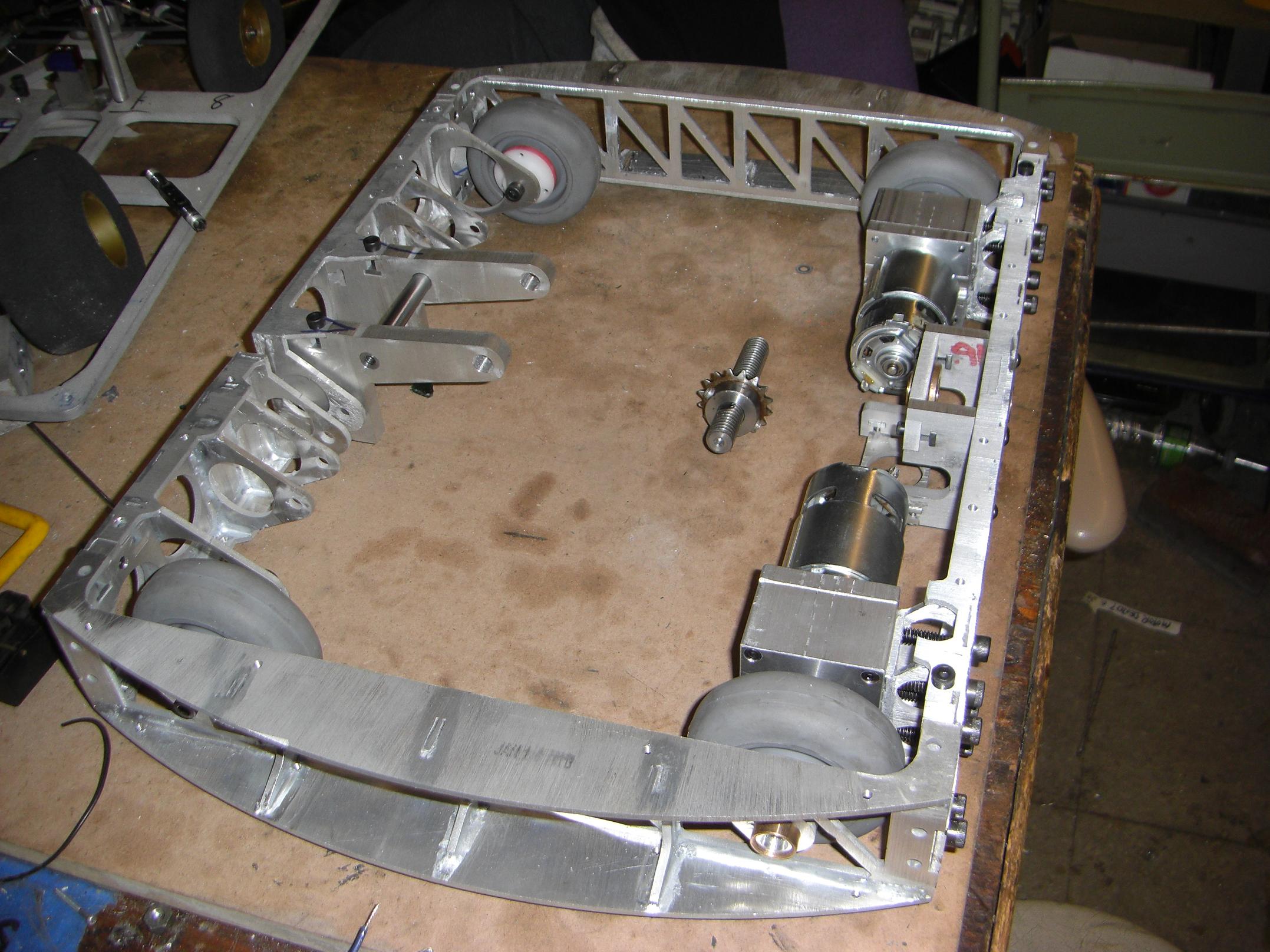
A little bit of frame assembly, now with clamp actuator bracket and all four wheels.
…and now with both actuators.
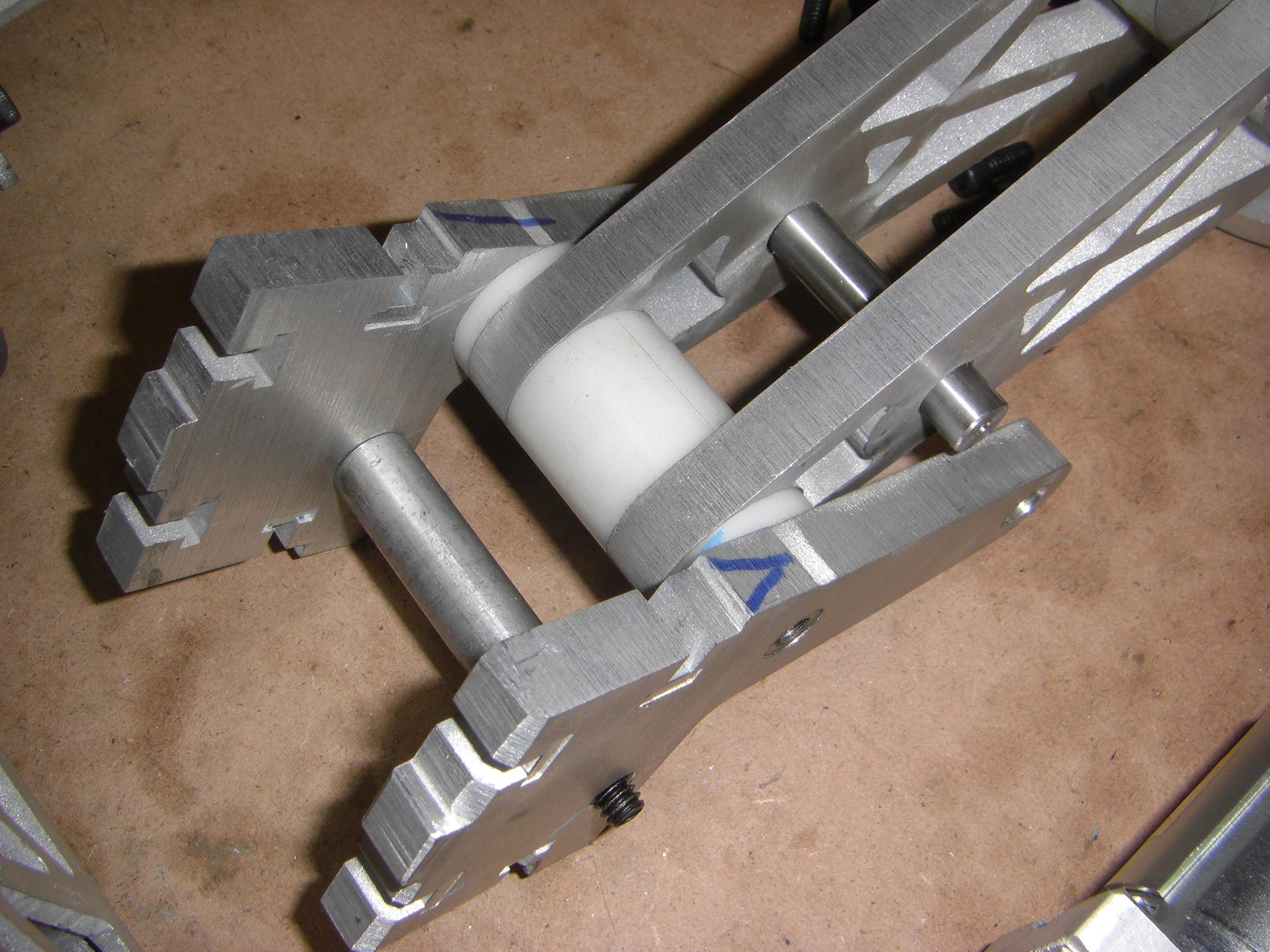
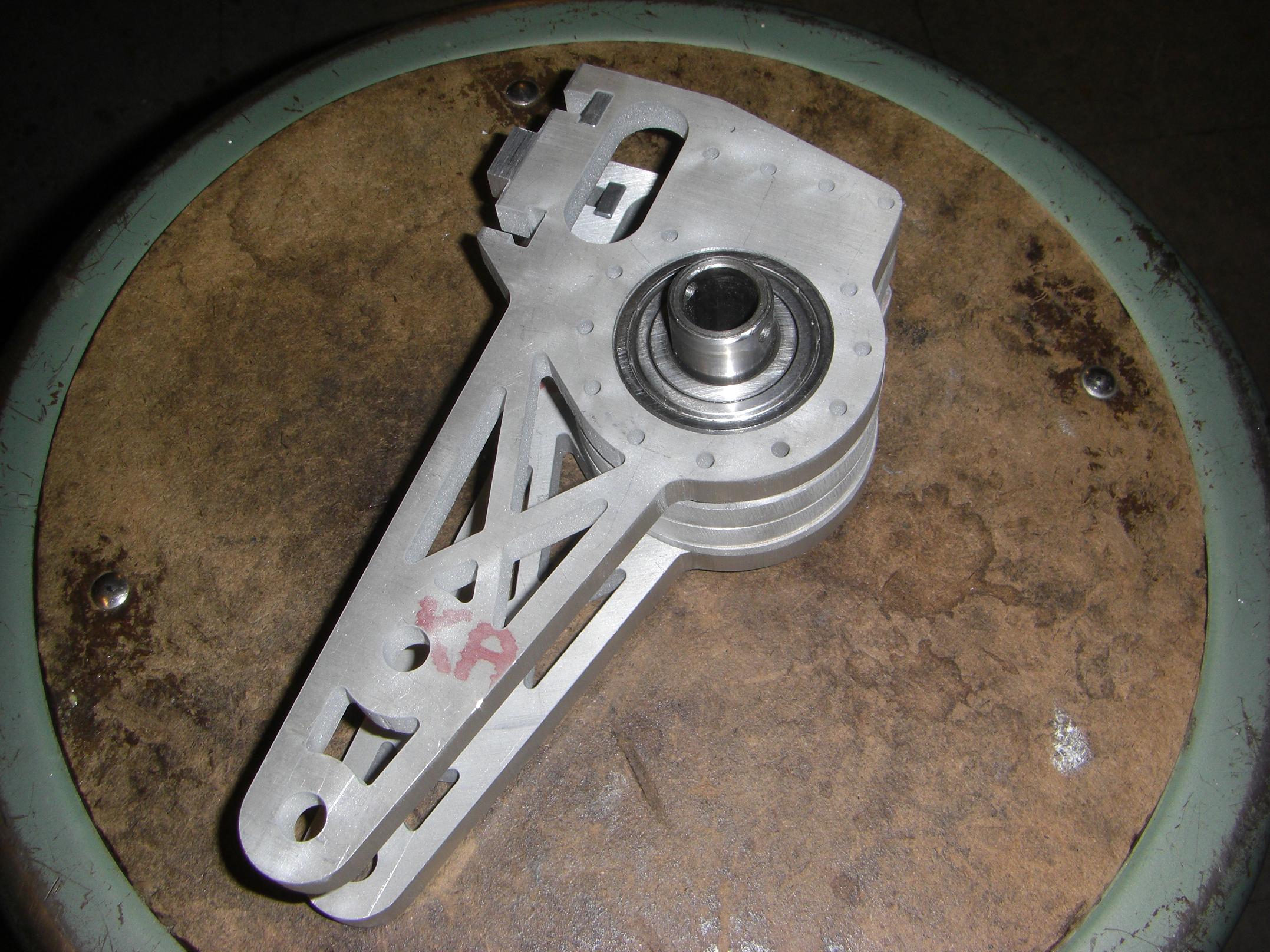
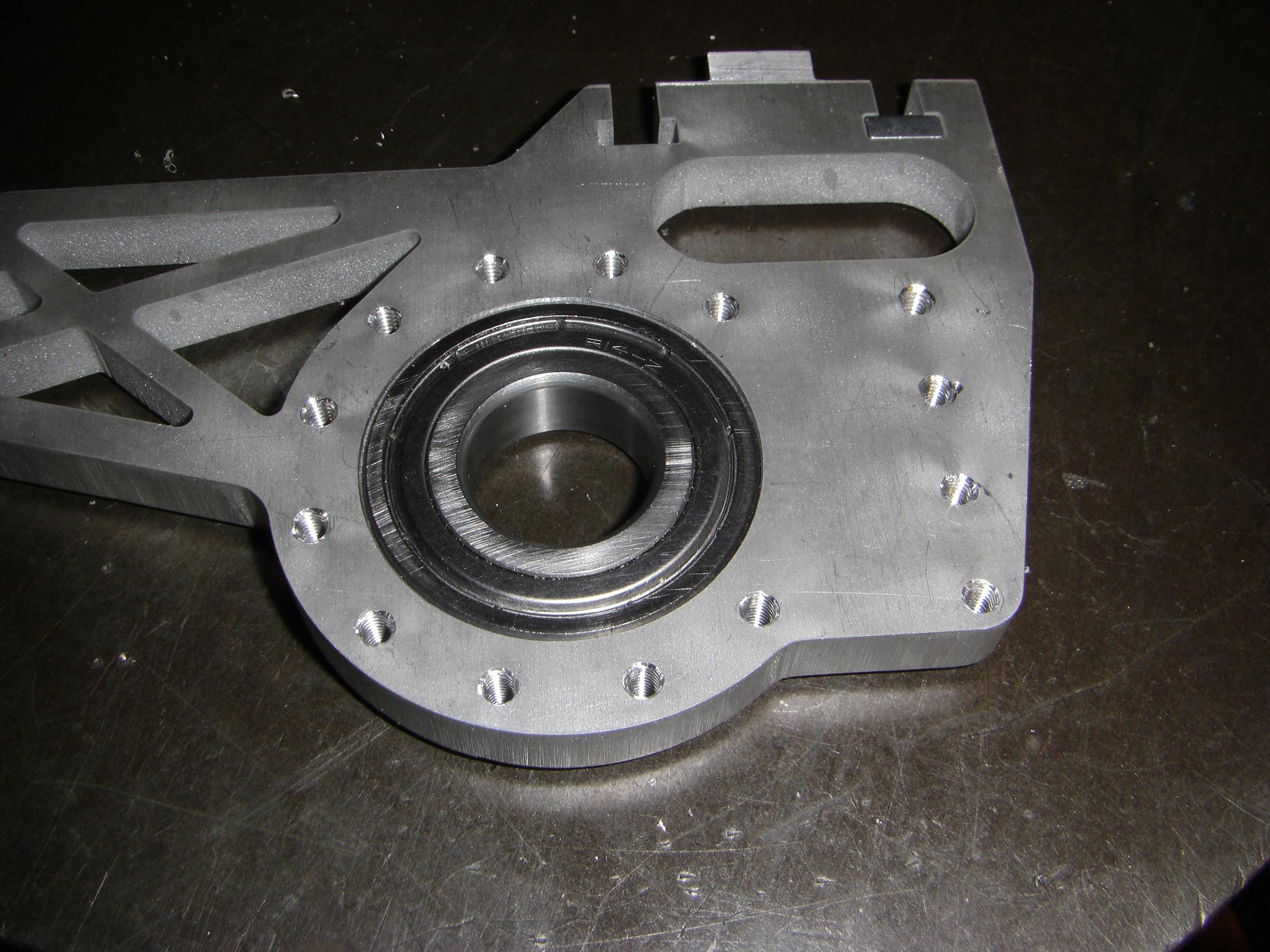
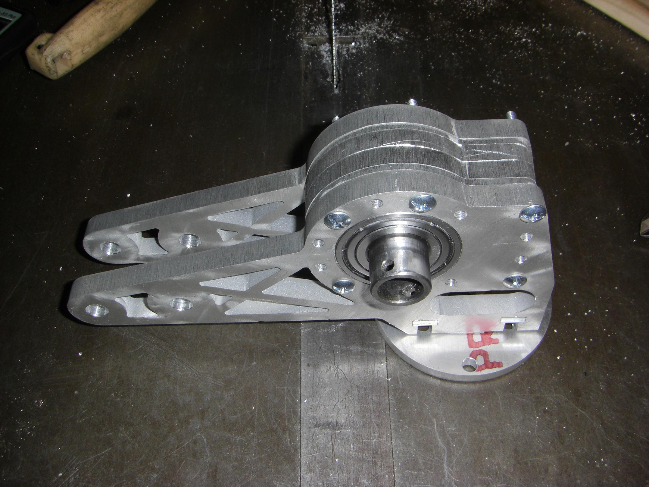
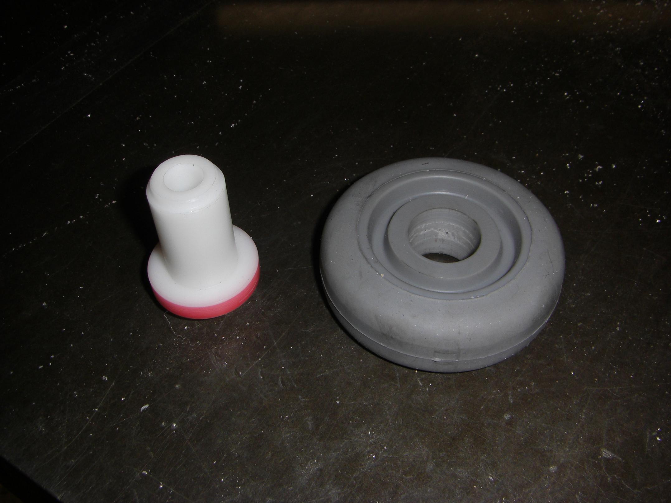
I machined some little round Delrin spacers to take up the axial slack on the swinging saw arm assembly. The hinge point itself is just aluminum on steel, but honestly – nothing here is moving fast enough to warrant a real set of bushings or bearings.
I made an end block for the actuator leadscrew and went ahead with a test assembly of the saw arm. Due to using a longer bushing than I intended to originally, the saw doesn’t swing back into the robot quite as far as I anticipated. This can be corrected, but wasn’t critical enough to warrant taking everything apart.
Here’s the actuator test mounted in the robot.
I guess this is still a Pretend-o-Pile, since there’s not enough there to be a robot just yet.
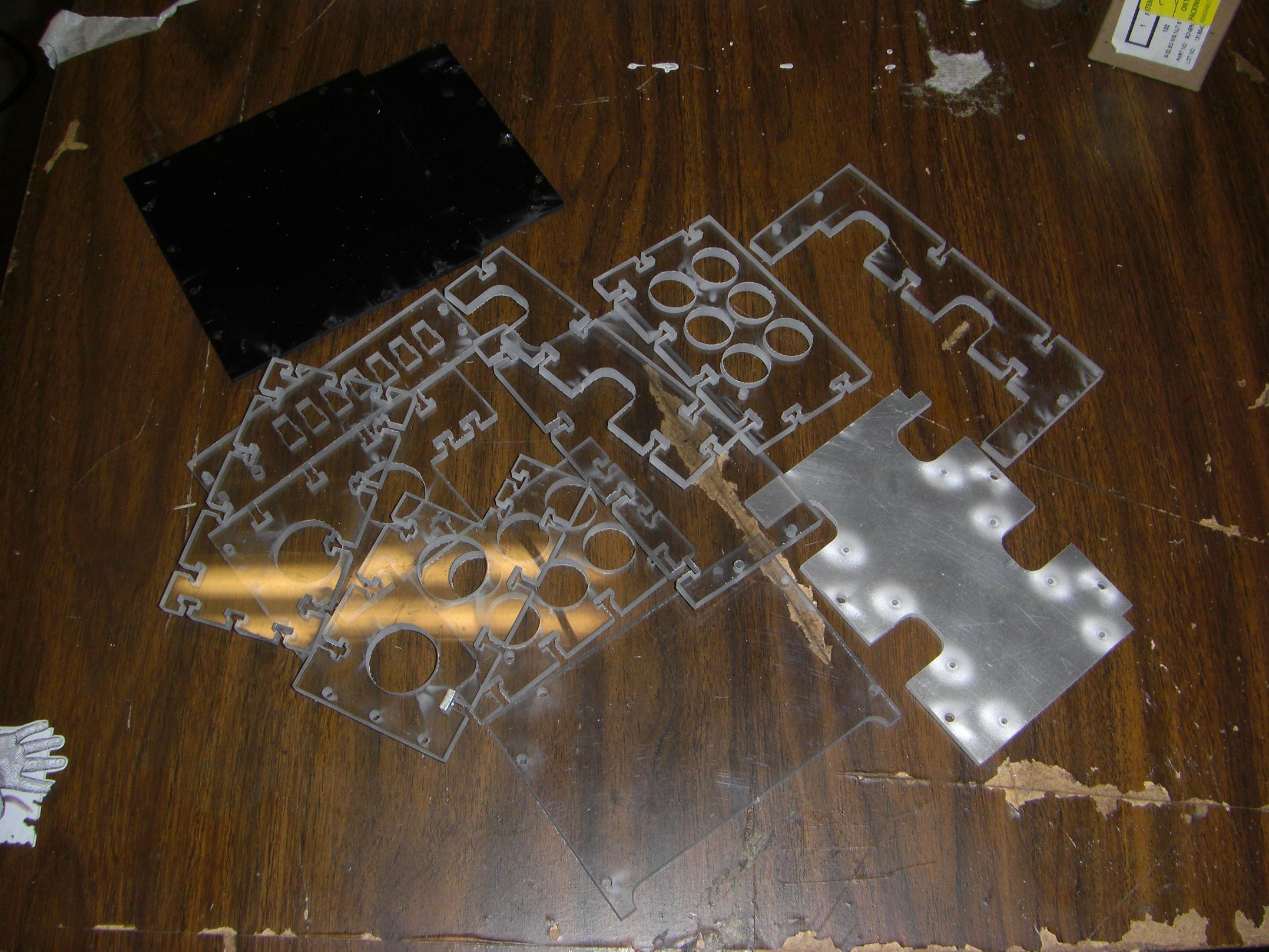
Alright, time for the last round of waterjetting! With the frame itself complete, I needed to start filling out the interior. Here are the electronics mounting facilities (the Ebay, so to speak) cut out of 1/8″ and 1/4″ polycarbonate, with plenty of T-nuts to put it all together.
The single 1/8″ aluminum plate will mount the two actuator ESCs, some Dimension Syren 25s and provide an additional heat sinking surface for them. They mount over the Victor 883s which I have on tap for drive controllers. The rounded cutouts in those plates allow me to access the wire terminals of the Victors without taking apart everything.
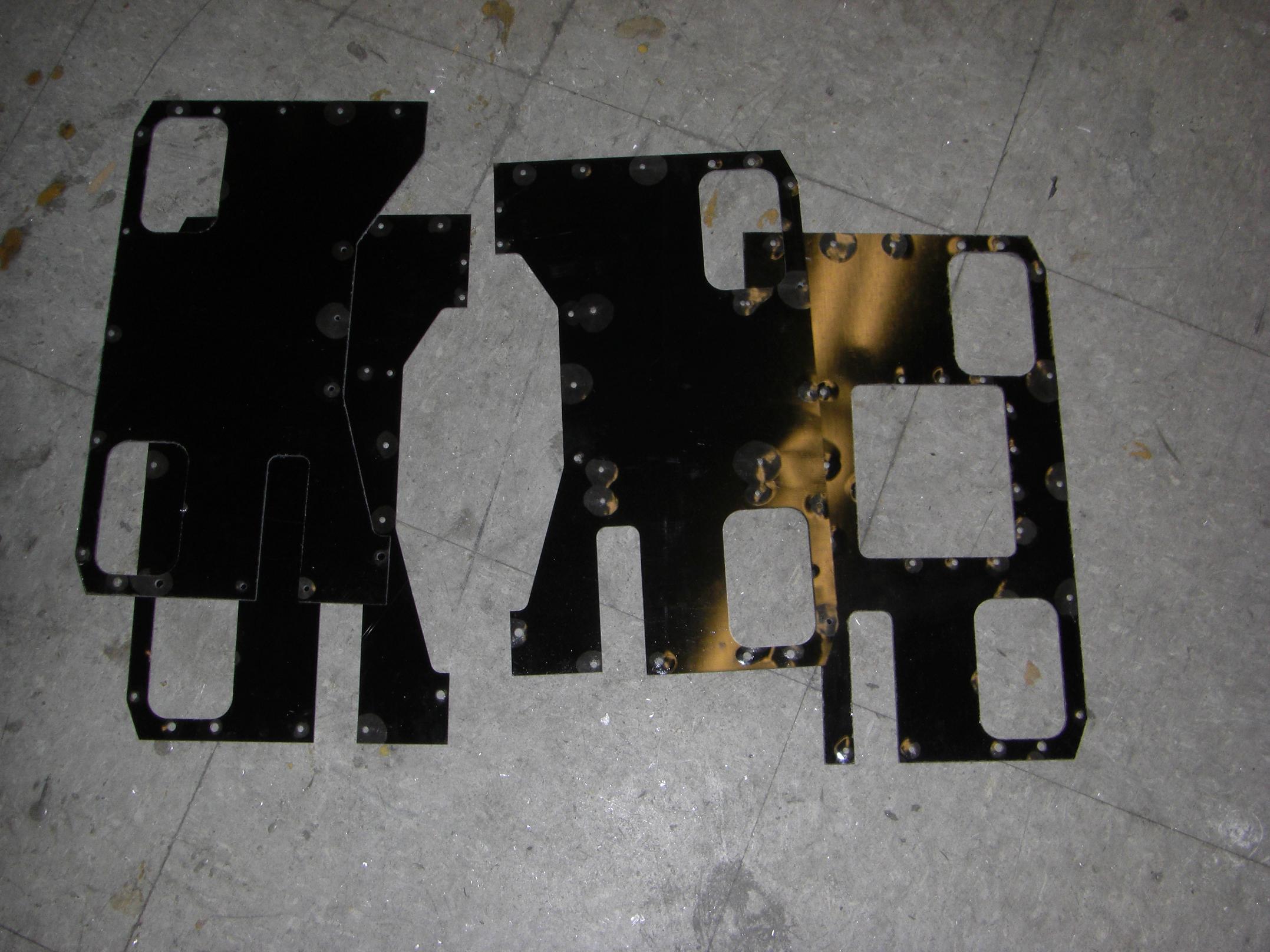
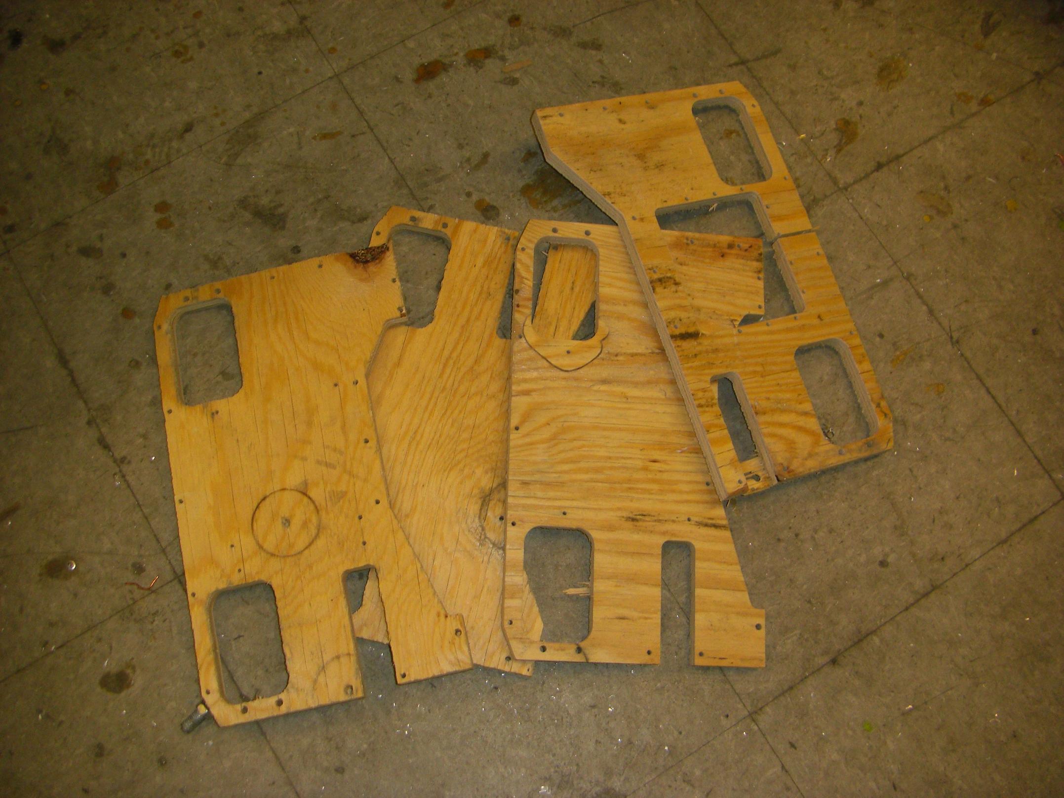
Finally, the top and bottom plates!
These are made of 1/16″ FR4, which I seem to favor across all my bots. I like it – it’s relatively cheap and stiff, and also nonmetallic. The one downside is that it does not waterjet very well. The layers tend to delaminate on a pierce due to the jet pressure forcing abrasive between them. To mitigate (but not completely avoid) this, I usually cut sheets of laminates over a waterjet brick or some kind of scrap backing material.
Delamination was especially bad on Überclocker’s plates because I wasn’t able to find backing material in time to catch an open spot on the machine. However, for Arbor, they came out much better. I clamped the 2 foot square FR4 sheet to a corresponding 2 foot square piece of 1/2″ plywood first. There is only minimal blowout around holes and locations where the material width is small.
That also yielded some conveniently robot-shaped 1/2″ pieces of plywood. Hello, supplementary anti-hammer armor.
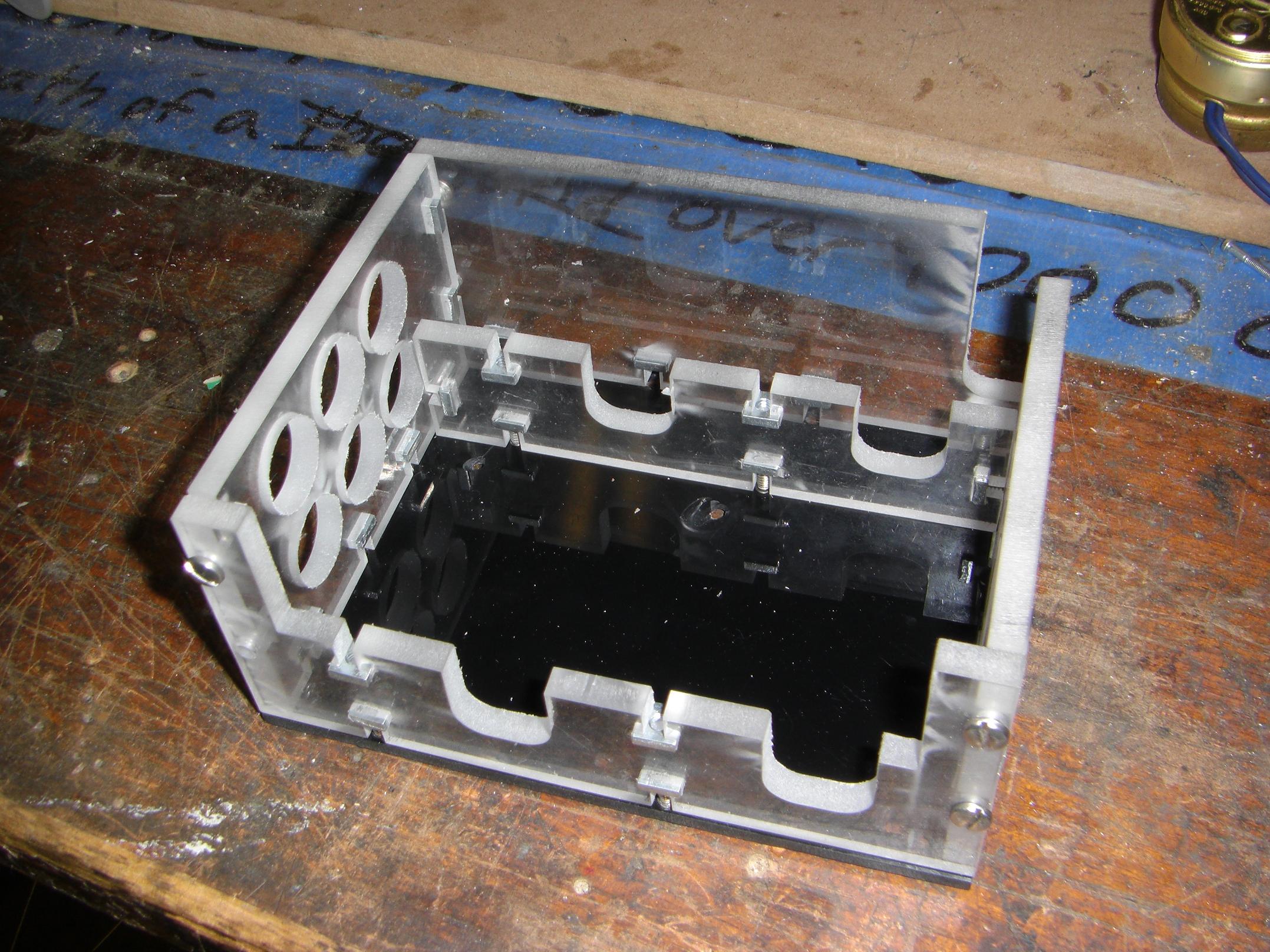
Some preliminary assembly of the Ebays. This is the right side, which houses all the important plushy electronic bits. The left side houses only the battery and relevant electricals. If you’re wondering what the big gaping hole in the top plate is, that’s a battery access panel which will have its own 1/4″ polycarbonate screen over it. This is so I don’t have to take out 9000 screws just to replace the battery.
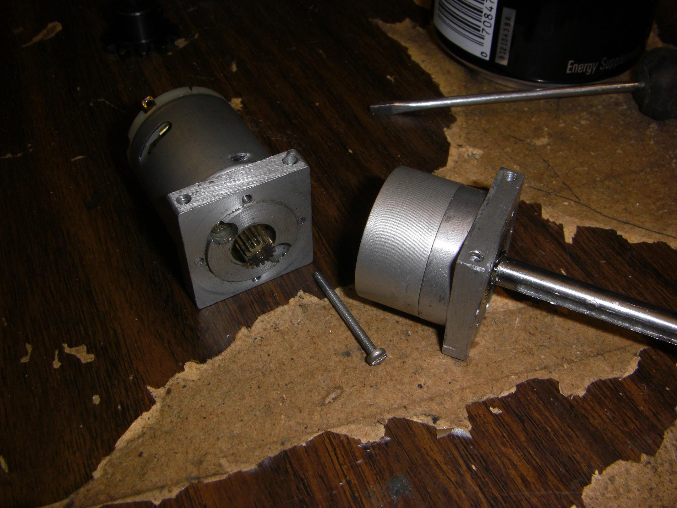
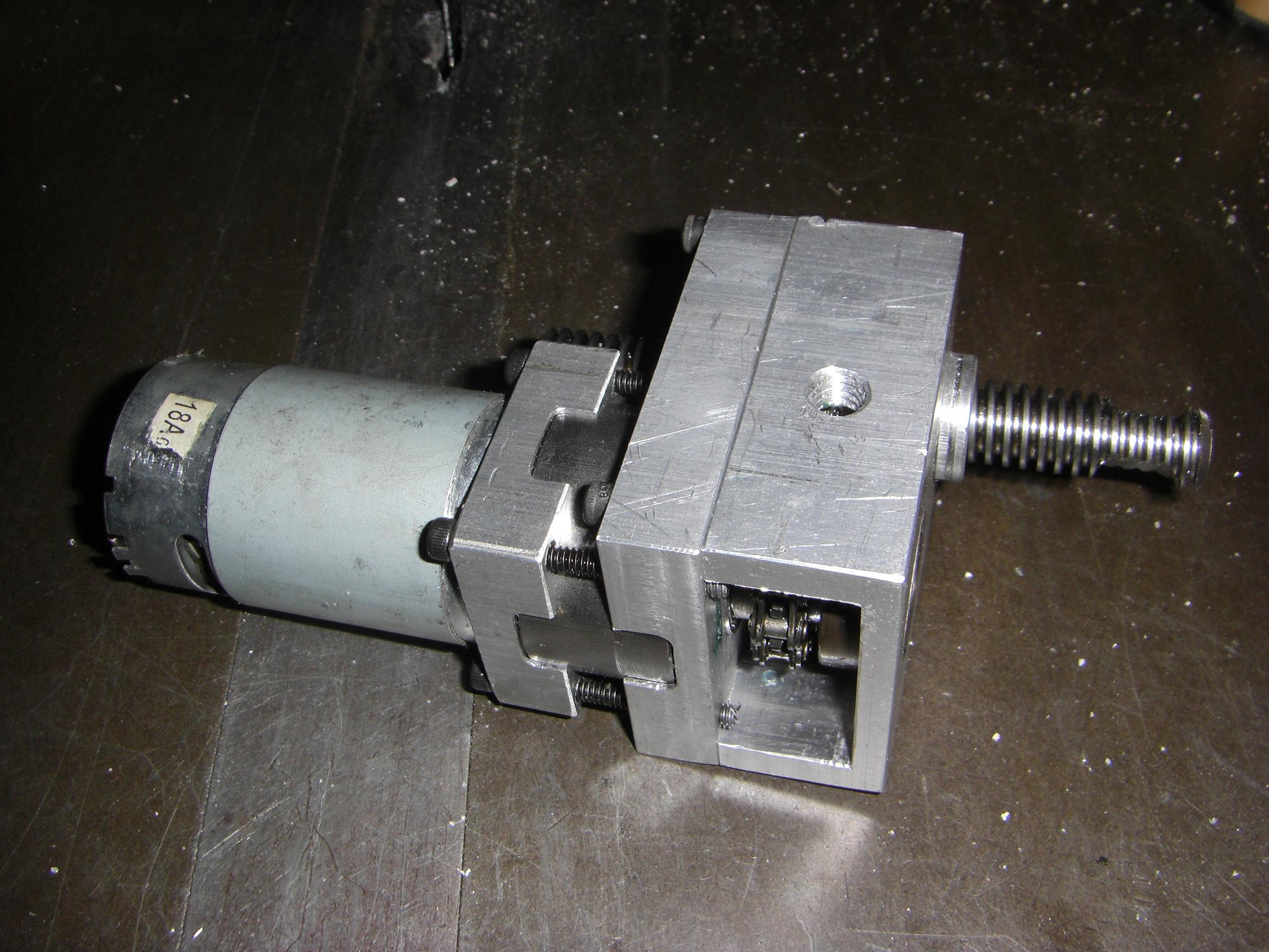
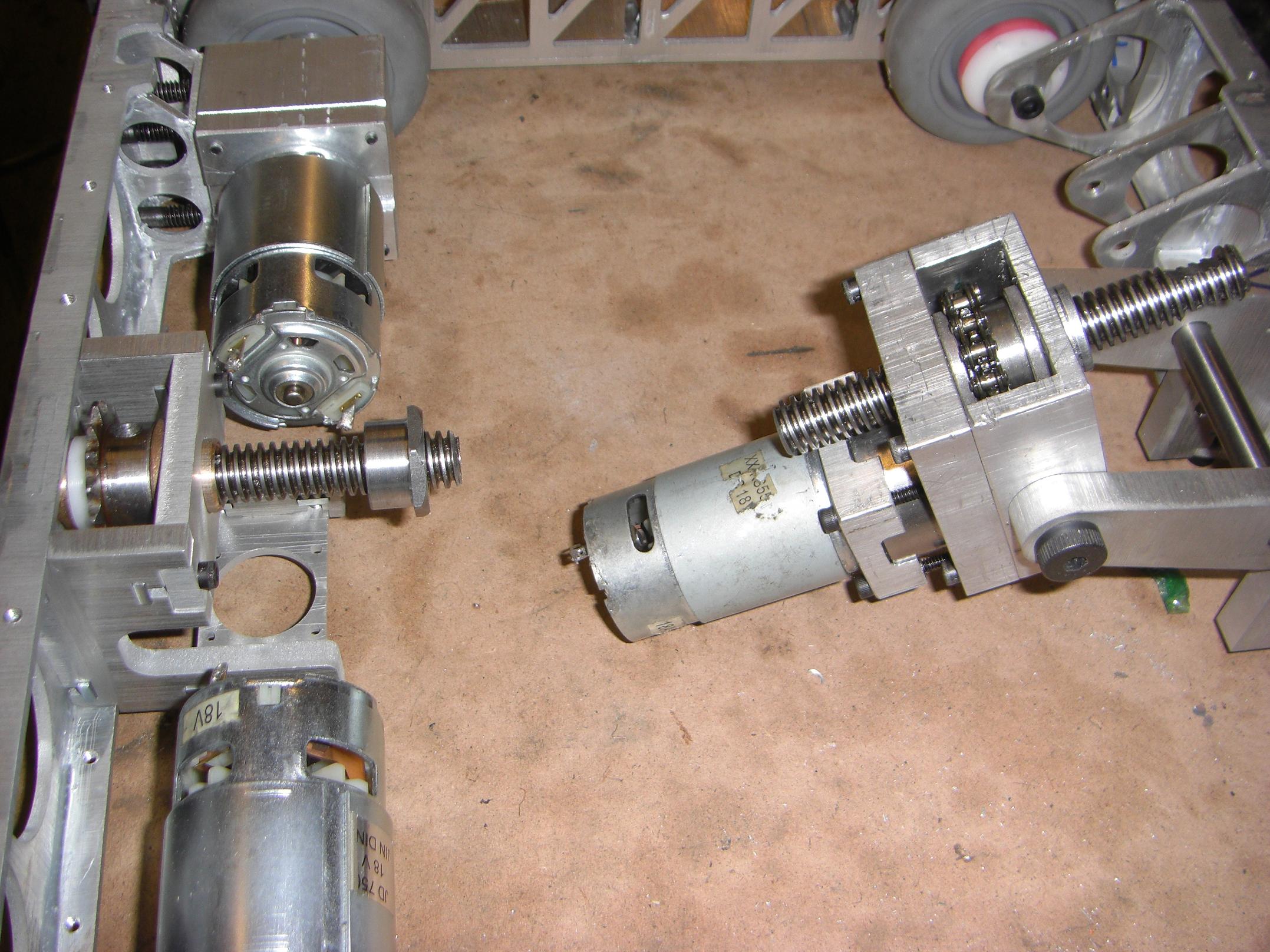
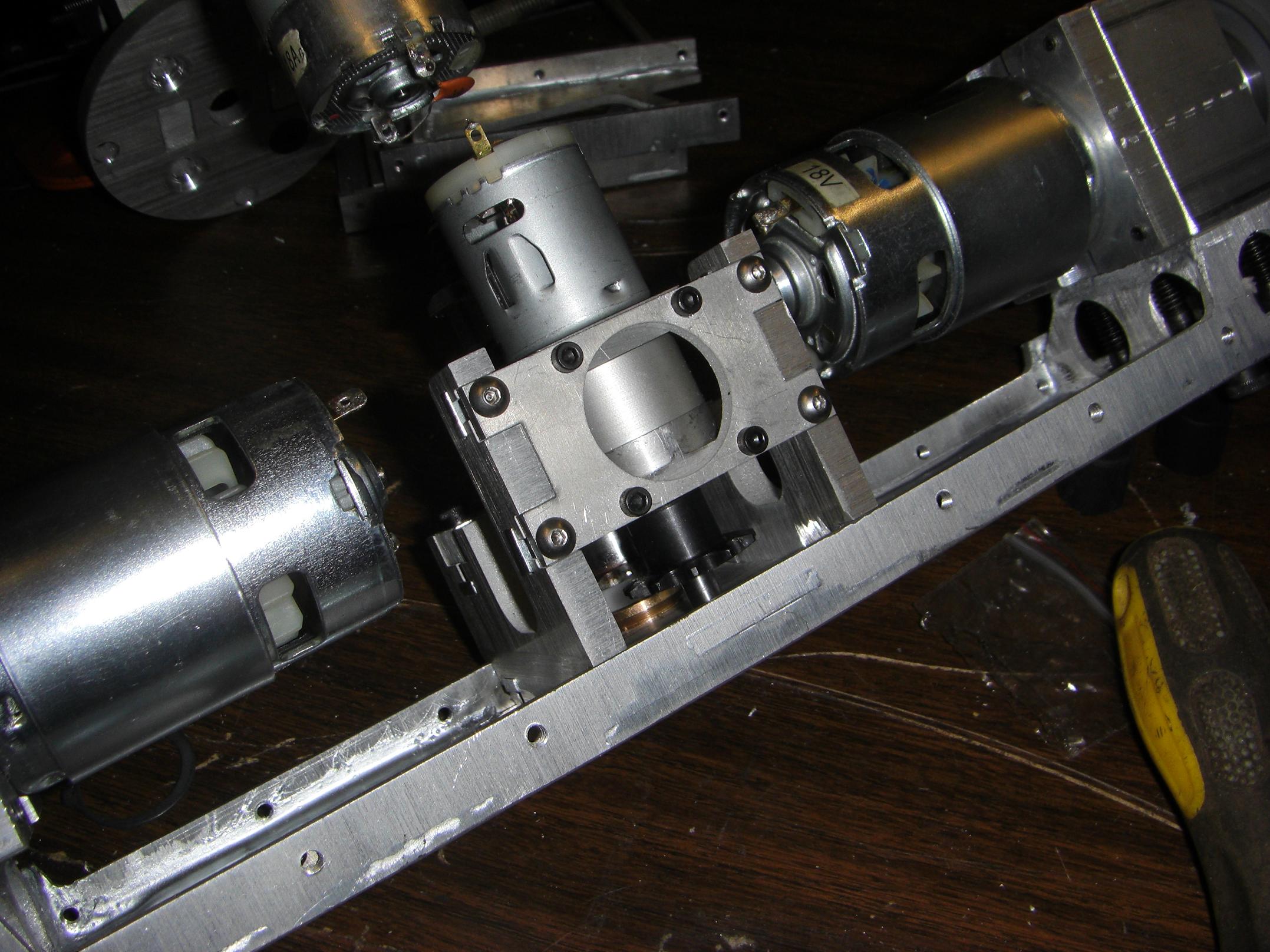
Back to random mechanical bits. For the longest time now, my 28mm Banebots gearmotor from Überclocker’s actuator has been sitting unused due to thrown motor windings. Kind of a shady failure mode, but it was convenient to have on hand for Arbor’s clamp actuator. To use it, I had to replace the motor.
I found a 380-size motor that was wound for 18 or 24 volts – an unusually high voltage for such a small motor. Generally, motors like that are wound for 3 to 12 volts.
Running a 18 volt motor would bring the clamp speed and power down to reasonable levels.
I pulled the pinion off the stock motor and smashed it onto the new motor. Since I took the brute force method of disassembling the gearbox to begin with (due to the low quality Philips head screws, which just sort of stripped the instant you tried to untighten them), I had to find replacement screws.
Fortunately, I was able to locate the #2 screws in a stockroom, so I was in business again.
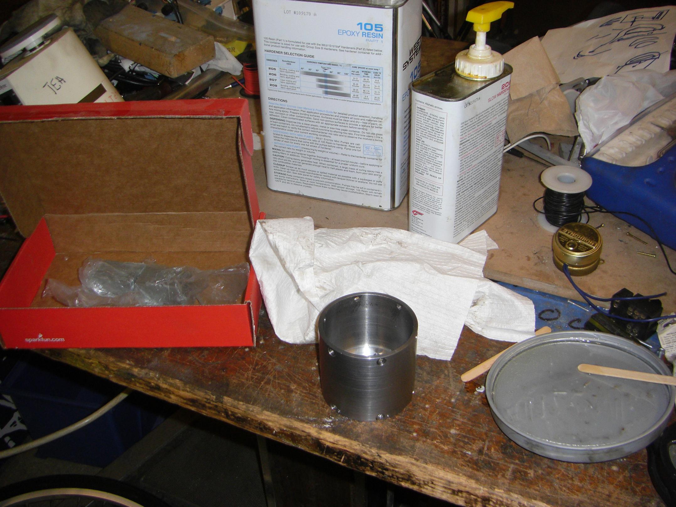
Alright, time to actually build Deathrunner. I’ve just been twirling an empty shell up until this point. I broke out the epoxy and custom segmented magnets and cleared the work table of all ferrous things.
This was the quickest magnet installation ever, in part because the magnets are already shaped in a circle. So it was just a matter of dropping them in while covered in epoxy.
I put the magnet can on top of a radiator to cure.
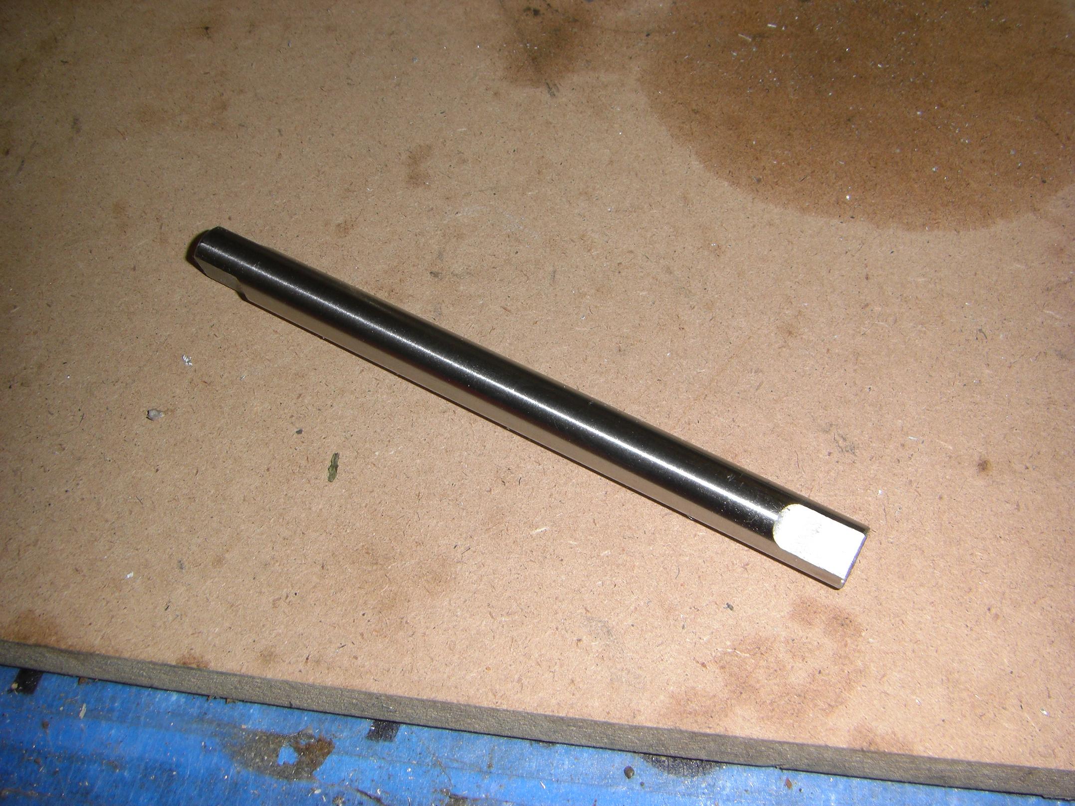
Instead of watching glue dry, I made the motor shaft. While a 10mm shaft has been pictured in just about all Deathrunner photos so far, it’s the stock shaft from the original outrunner motor, and is not only too short, but very dinged and scratched from countless slipped set screws.
I ordered a short section of 10mm precision ground shafting from McMaster for the new motor shaft. All I really had to do was put 3 flats on it, which was a short operation.
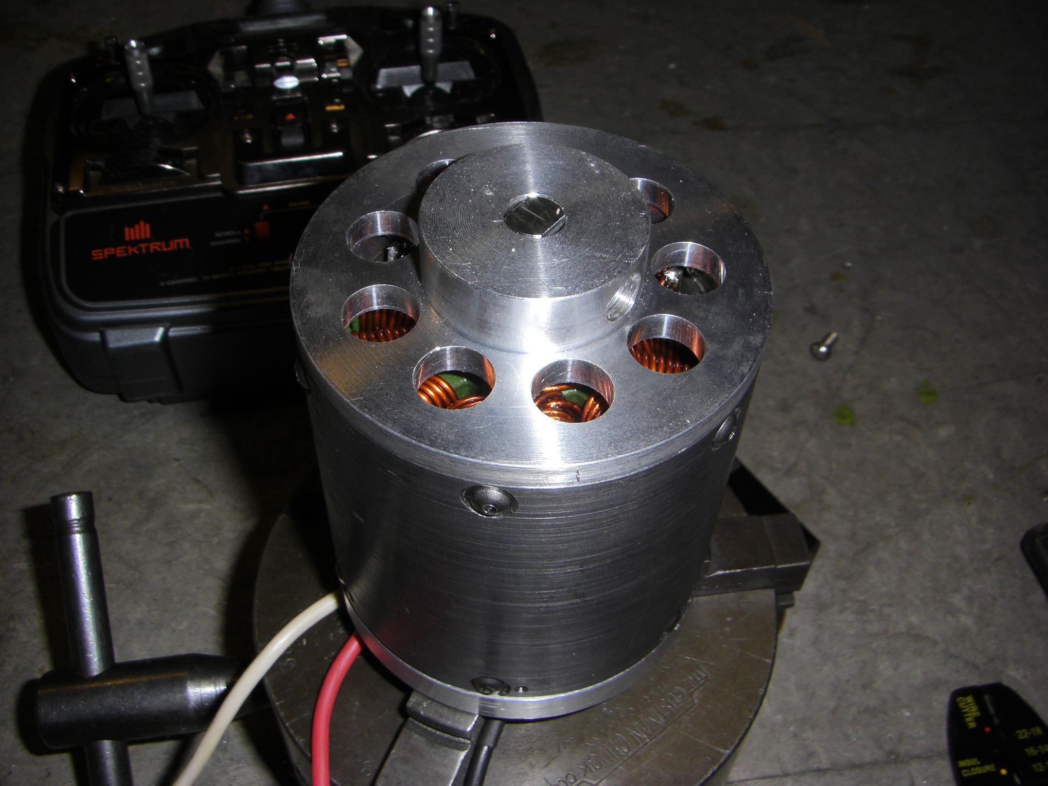
Look, it’s an assembled, fully magnet’d Deathrunner!
Installing the stator was originally going to be controlled and gentle, but the magnetic attraction between magnets and stator was so strong that it sucked the stator out of my Controlled Stator Installer (i.e. a set of channel-lock pliers) and just sort of crammed itself together in what must have been less than 100 milliseconds.
The impact moved the ring bearing 2mm into the motor, but this isn’t enough to disturb motor operation.
So, I have Deathrunner fixed to a quasi-static surface. What’s next?
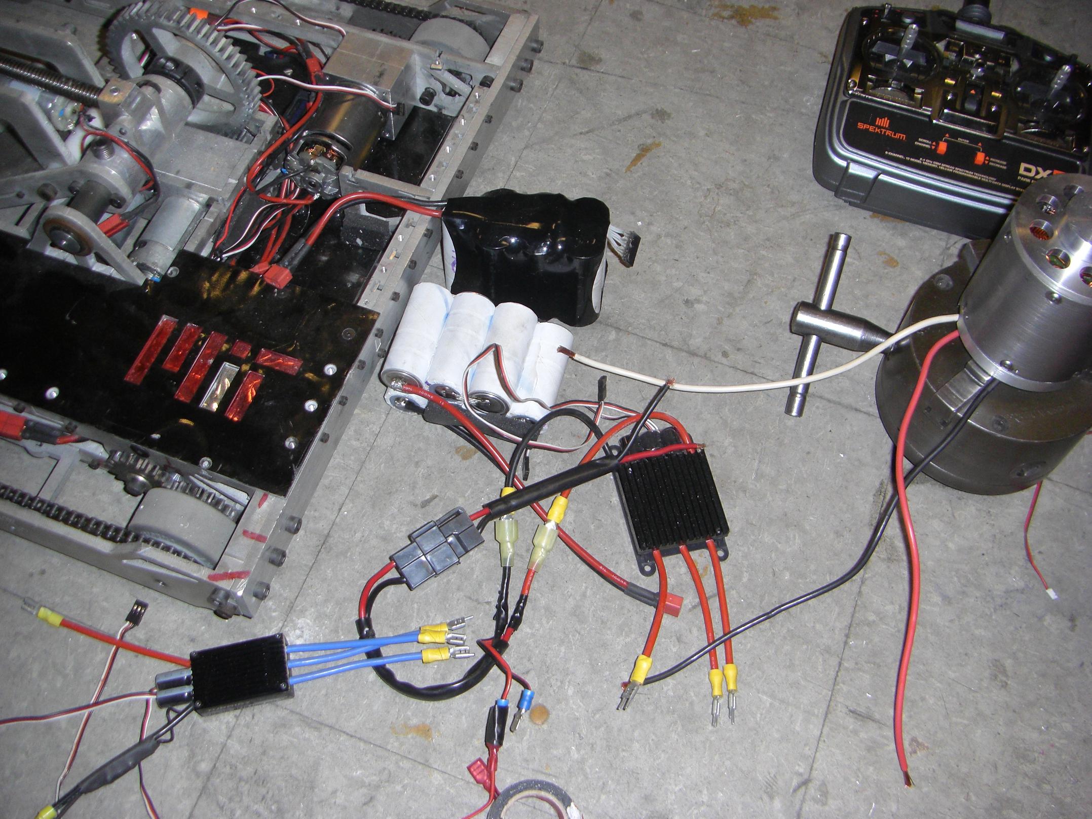
This totally legit testing rig involved two battery packs and all of Überclocker. I didn’t have a spare receiver, so needed one to test, and the large controllers I have require 5 volt power to run. The only system that satisfied all these criteria was Clocker.
Conclusion: I approve.
The estimated motor speed is around 3,300 RPM. This puts the saw at a no load speed of about 110 RPM, which, while fast for a cold saw, is good enough for a robot weapon.
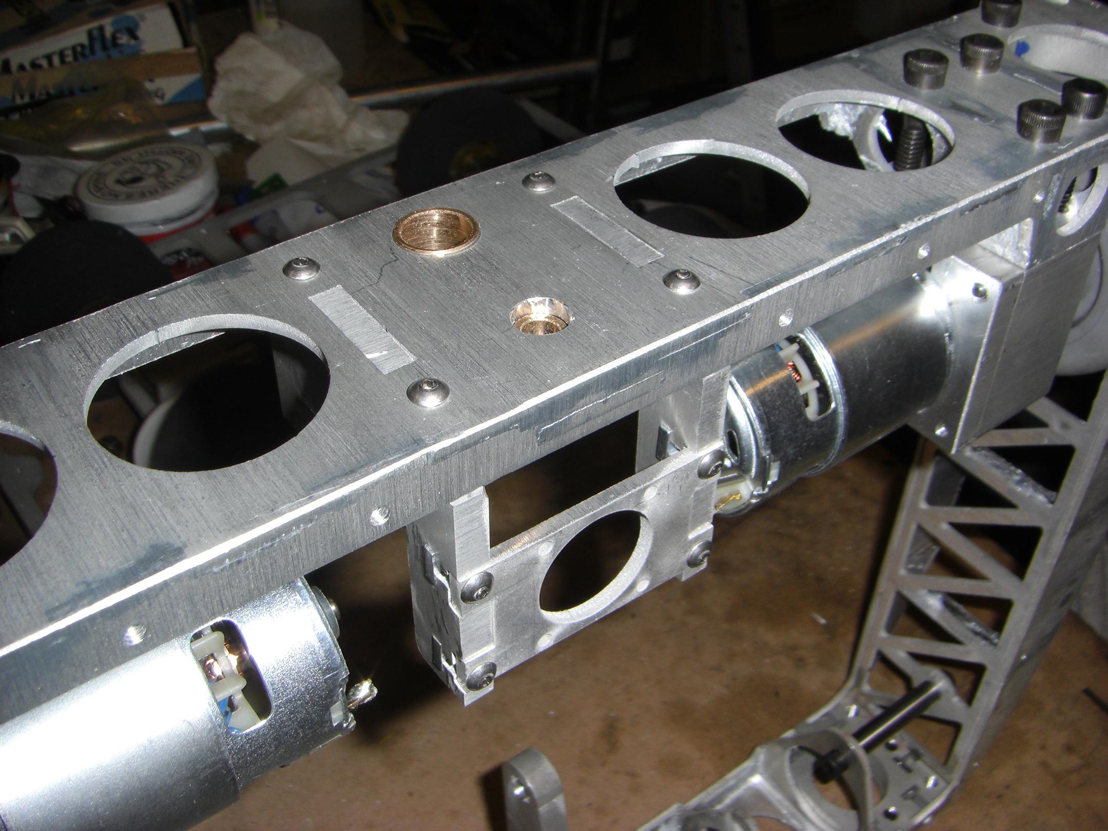
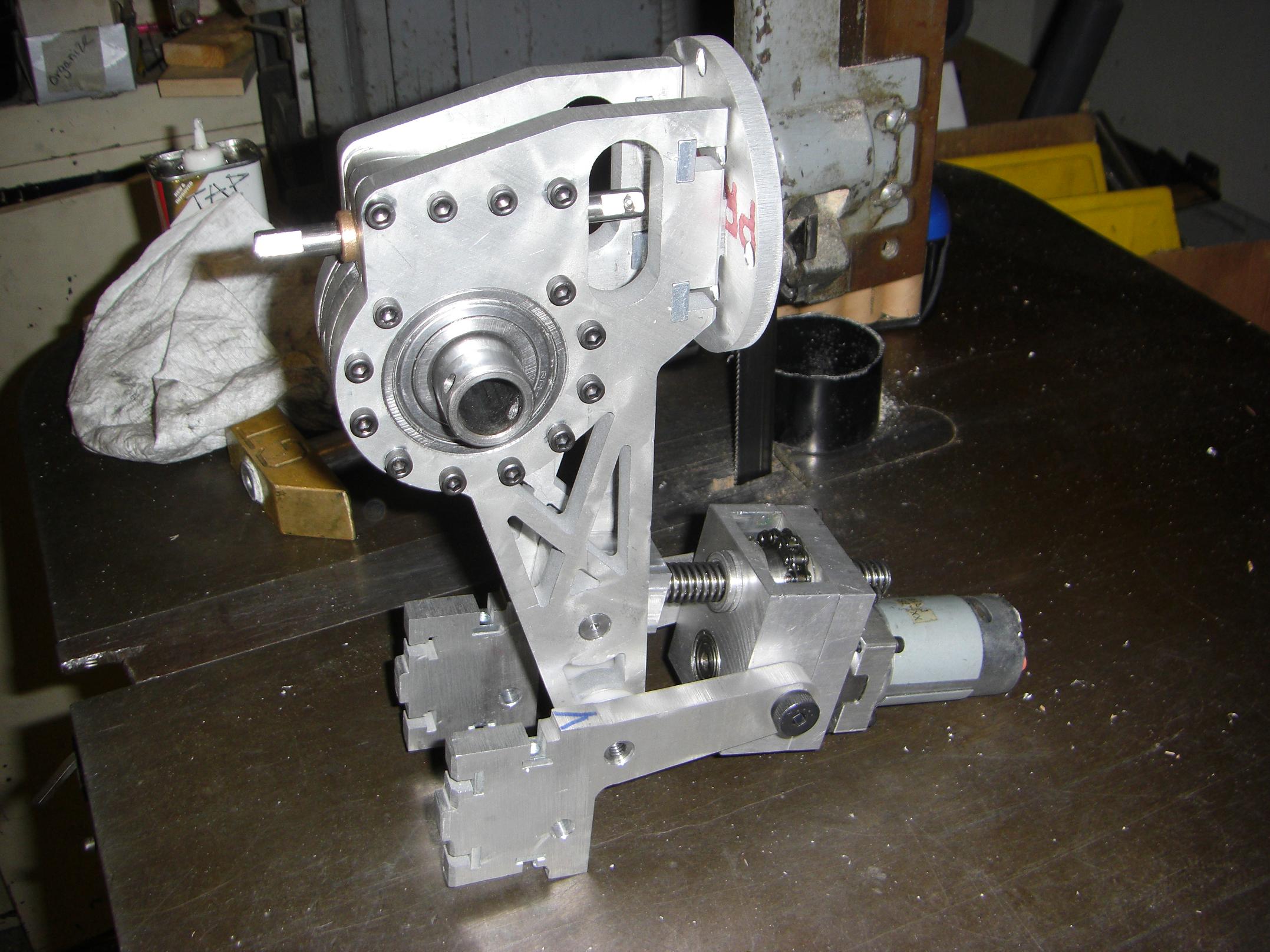
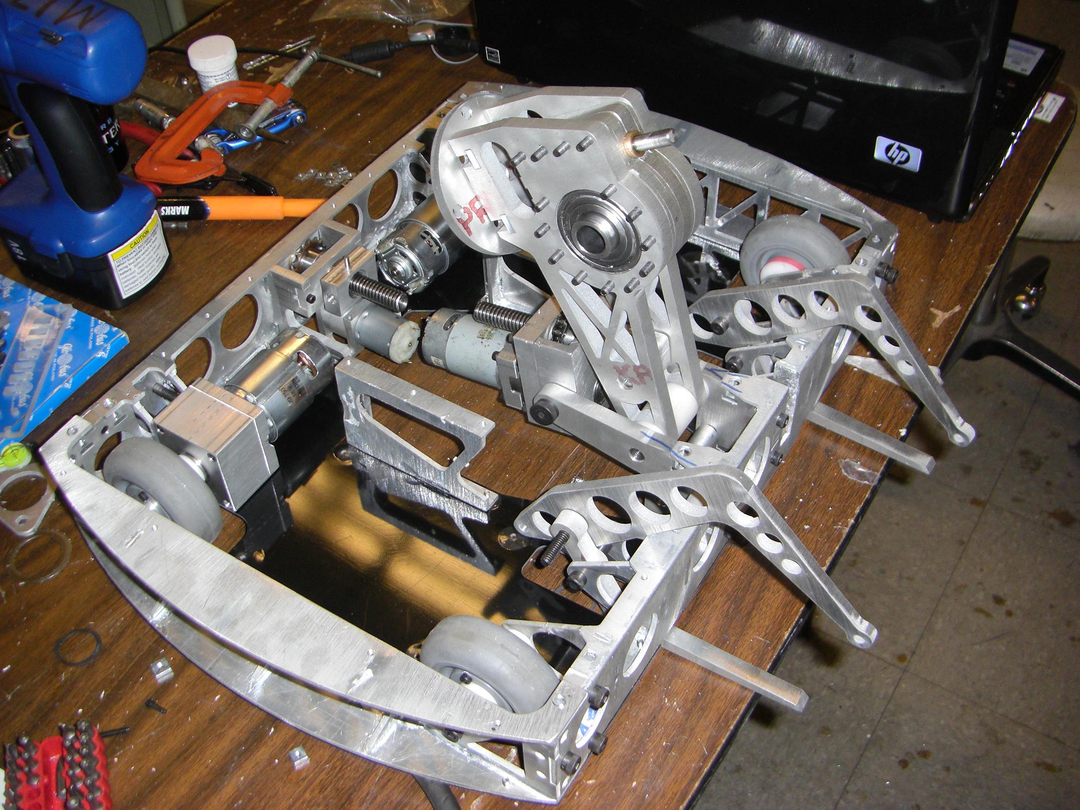
Alright, enough random fun. Time to get back to assembly. Here’s the clamp actuator motor situated in its mounting points. The clamp actuator also uses sprockets in lieu of gears.
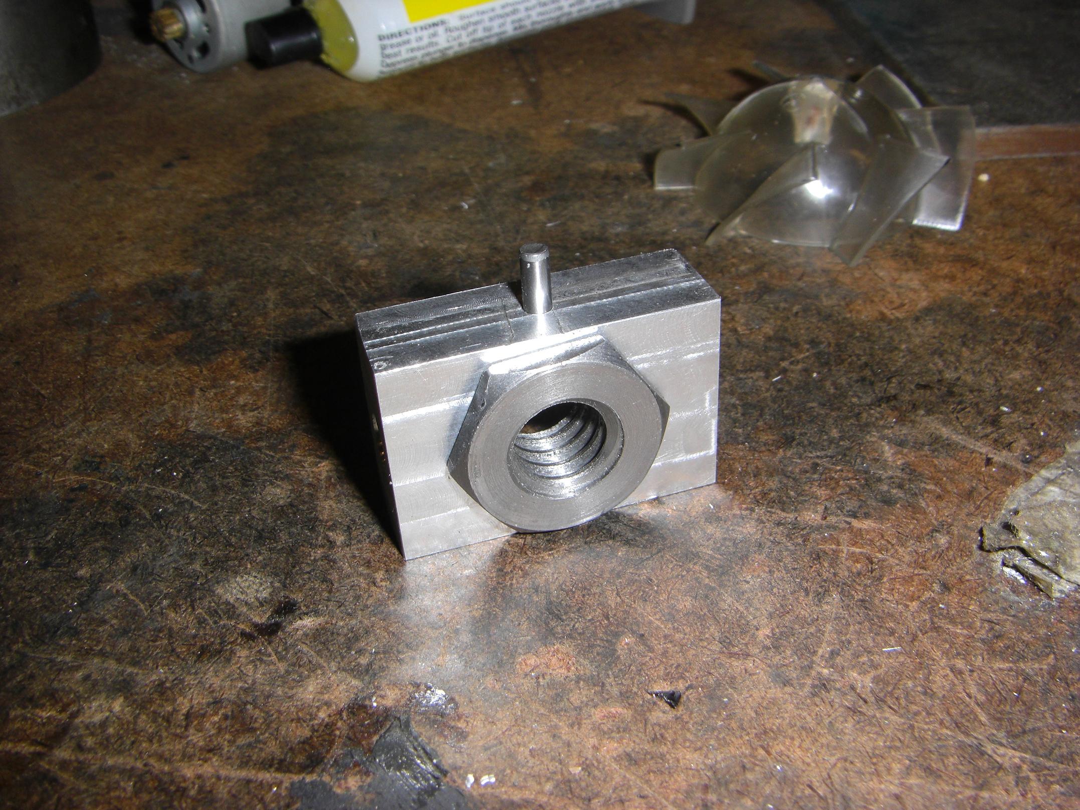
I made an aluminum block to embed the leadscrew nut in. Eventually, the clamp linkages themselves will attach to this block, so the nut may actuate them both at once.
The pin was put in after I realized I failed at making a good press fit, and the nut spun in the block.
With most frame-dependent components in place, I started mounting the bottom cover plates.
This was actually a bit nontrivial. Variances in fixturing while I brazed the frame pieces together coupled with inconsistent sanding and possibly even heat warping meant that NOTHING LINED UP THE WAY IT SHOULD HAVE.
Alright, so at least half the holes could be used. The other half? I had to clean out with a clearance drill for #6 and #10 screws first, then…
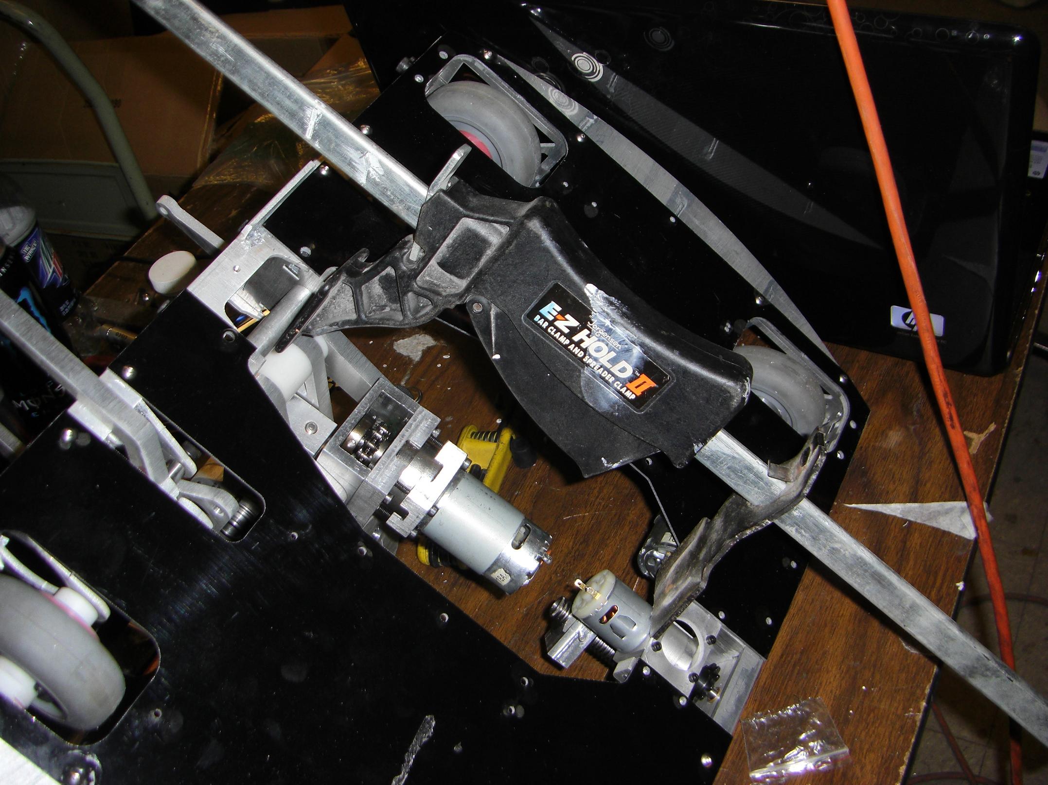
…bend some of the frame pieces into shape with a spreader clamp. Apparently, the front and rear rails are very slightly curved inwards, which supports the thermal warping hypothesis.
That’s fine, I bent them back out a bit, and all the holes lined up the way they should.
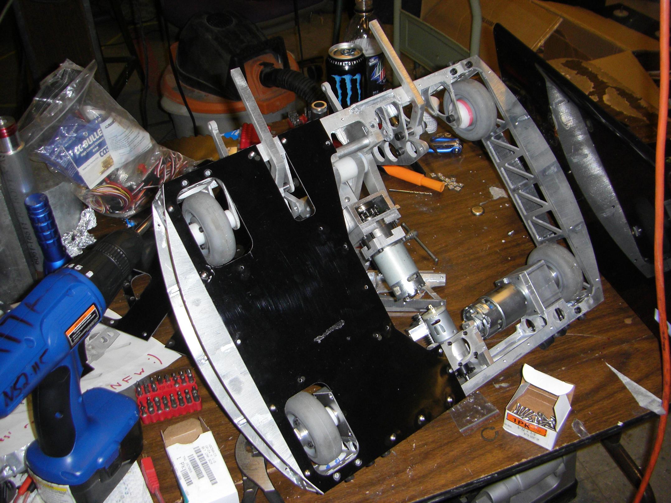
Both baseplates attached, now right side up. It’s starting to look a bit more cohesive now.
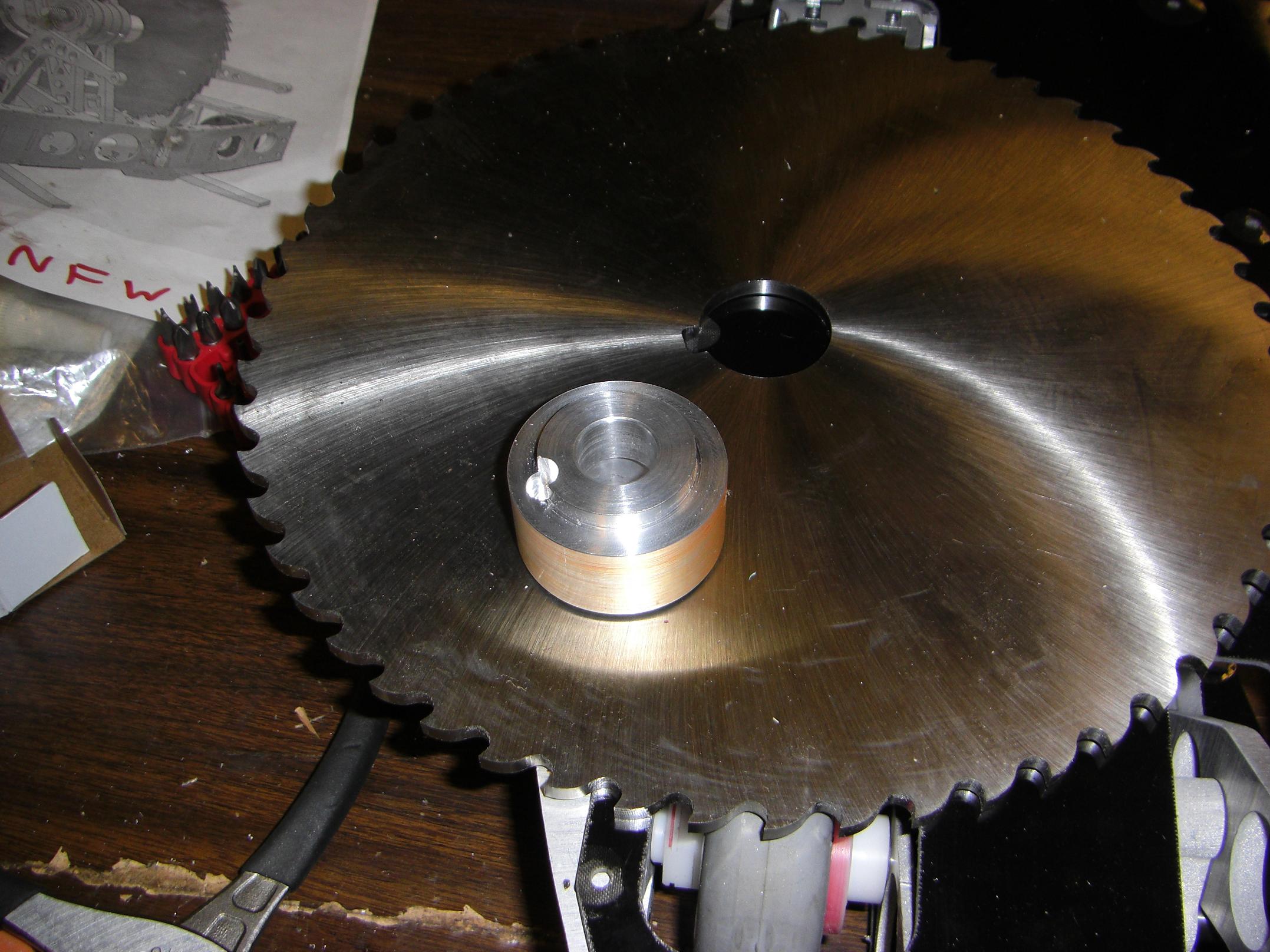
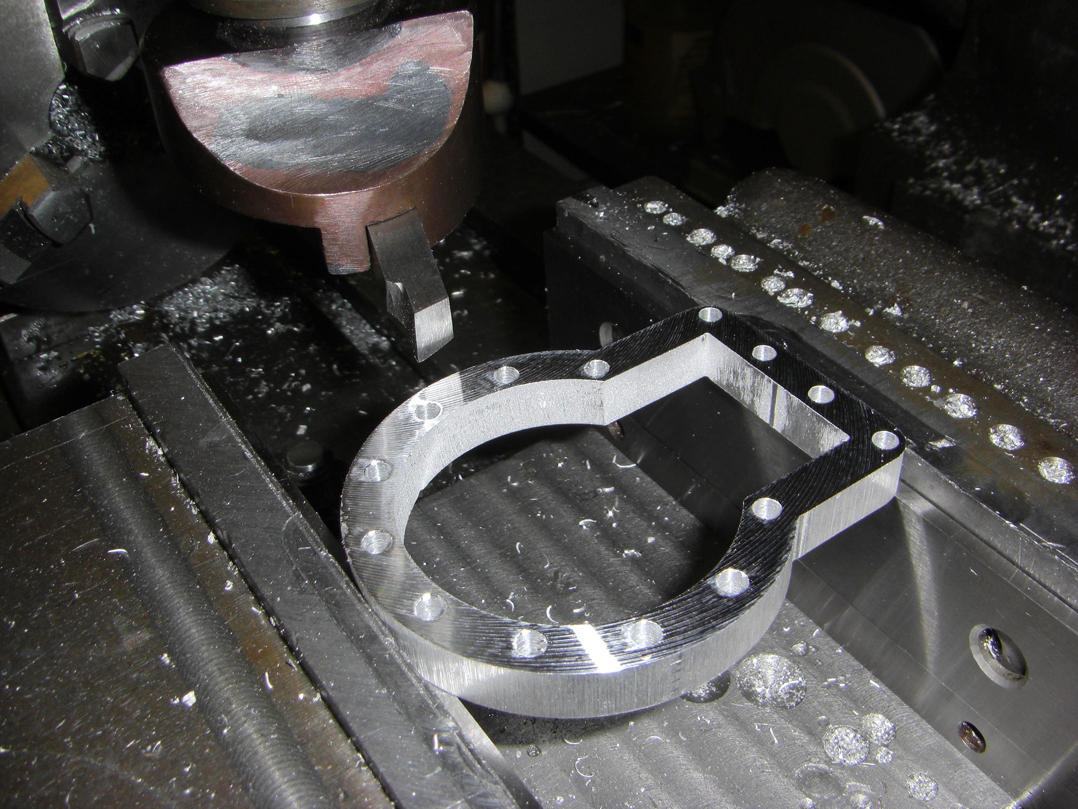
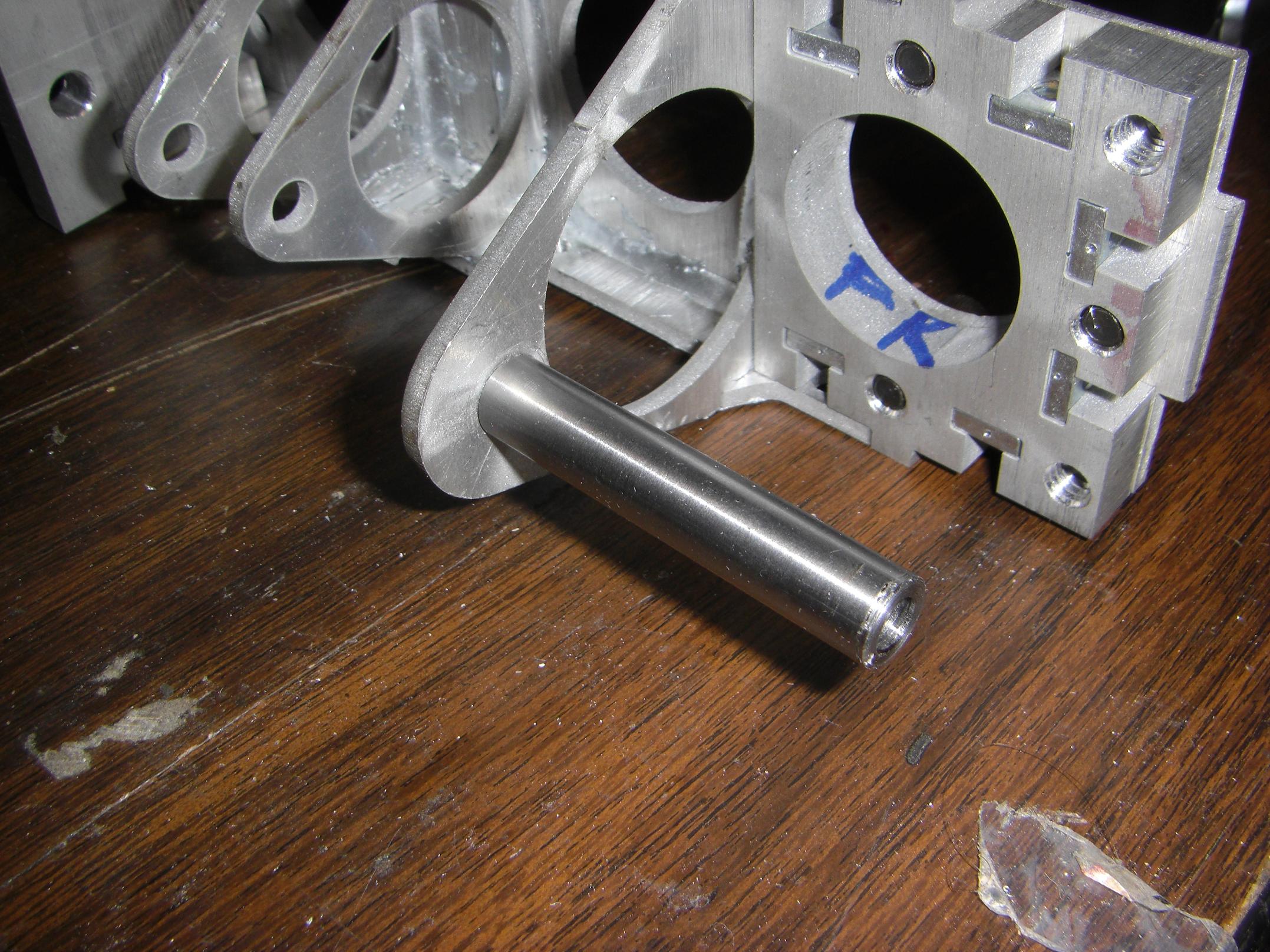
I popped off the saw blade hub using a 2 inch aluminum round. The offset round hole is for a dowel pin, which will keypeg the saw blade.
The orange appearance of the aluminum is due to my choice of layout fluid, namely Sharpie markers.
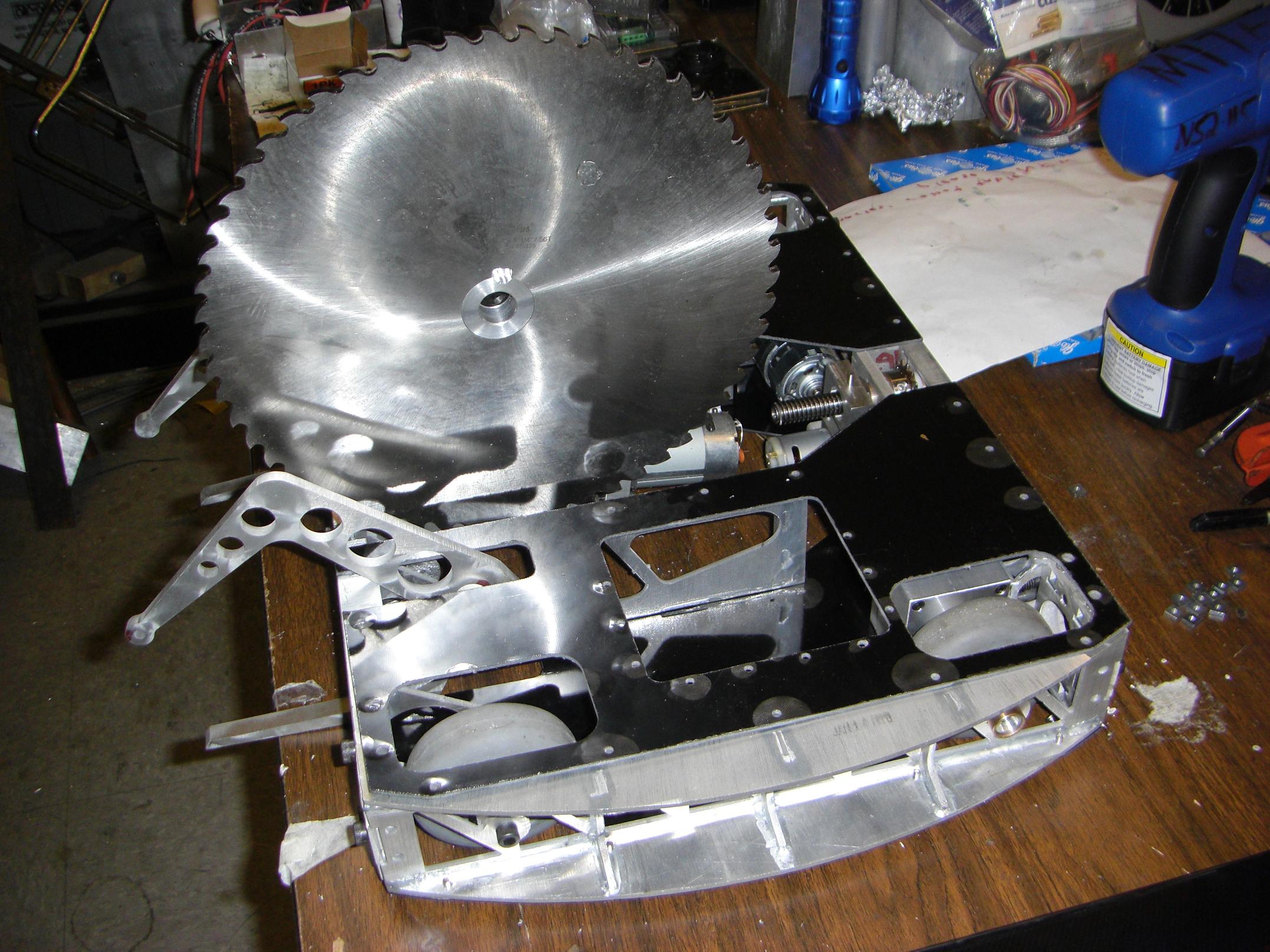
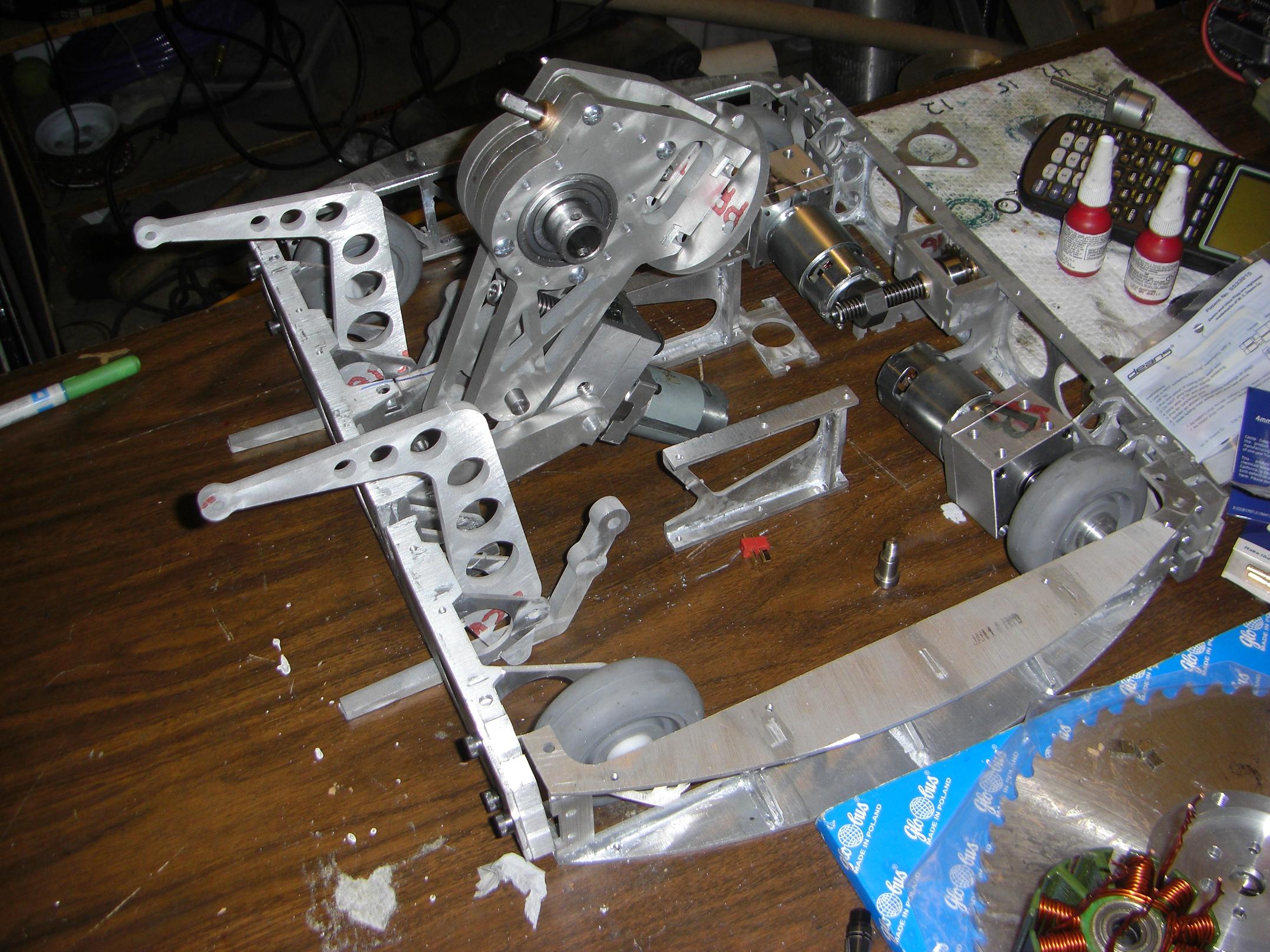
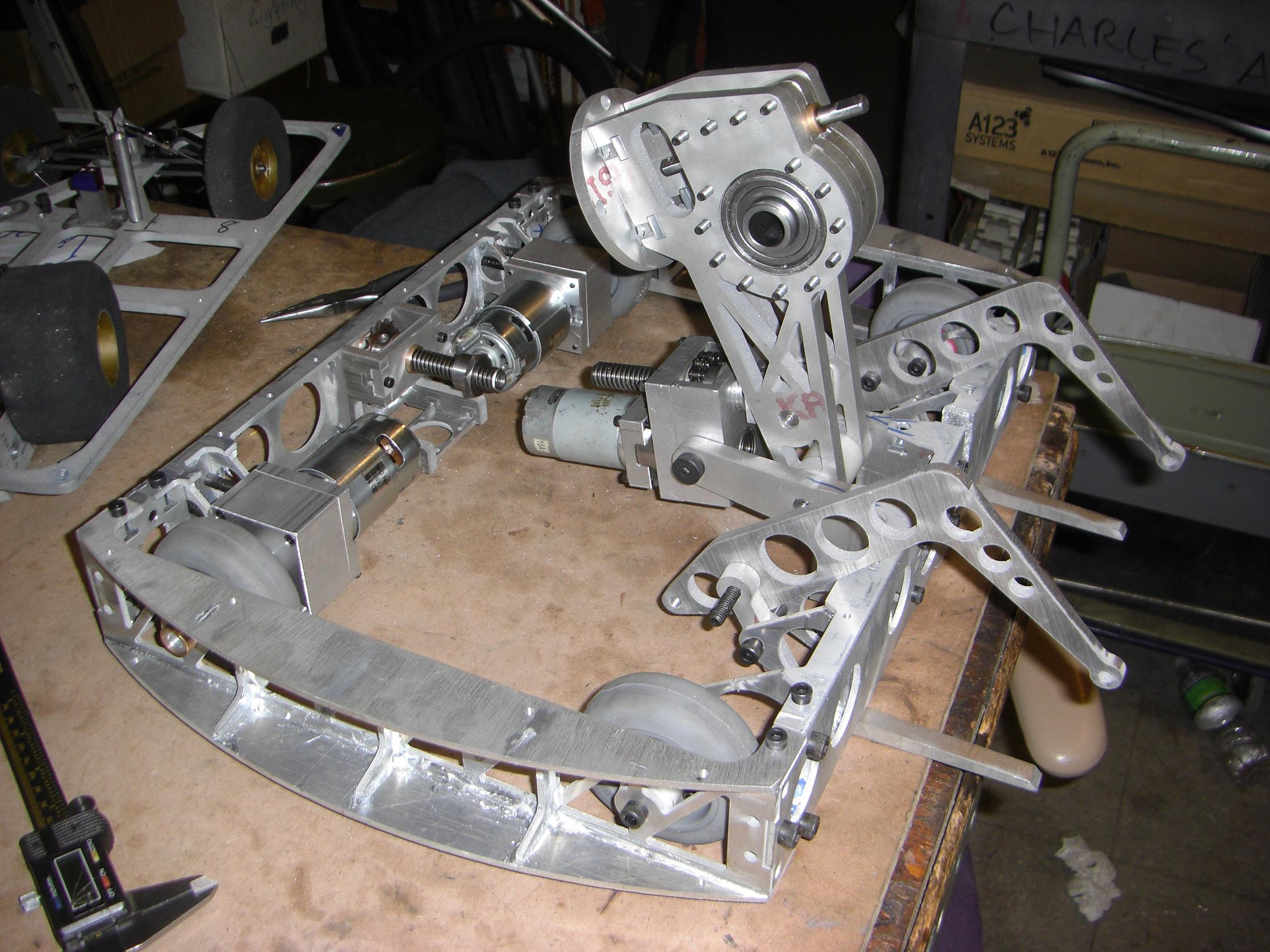
A wild Pretend-O-Bot appears.
I threw all the frame pieces together and mounted the saw. Very few things are actually fastened down right now, so this will all be knocked down again for more piecemeal work.
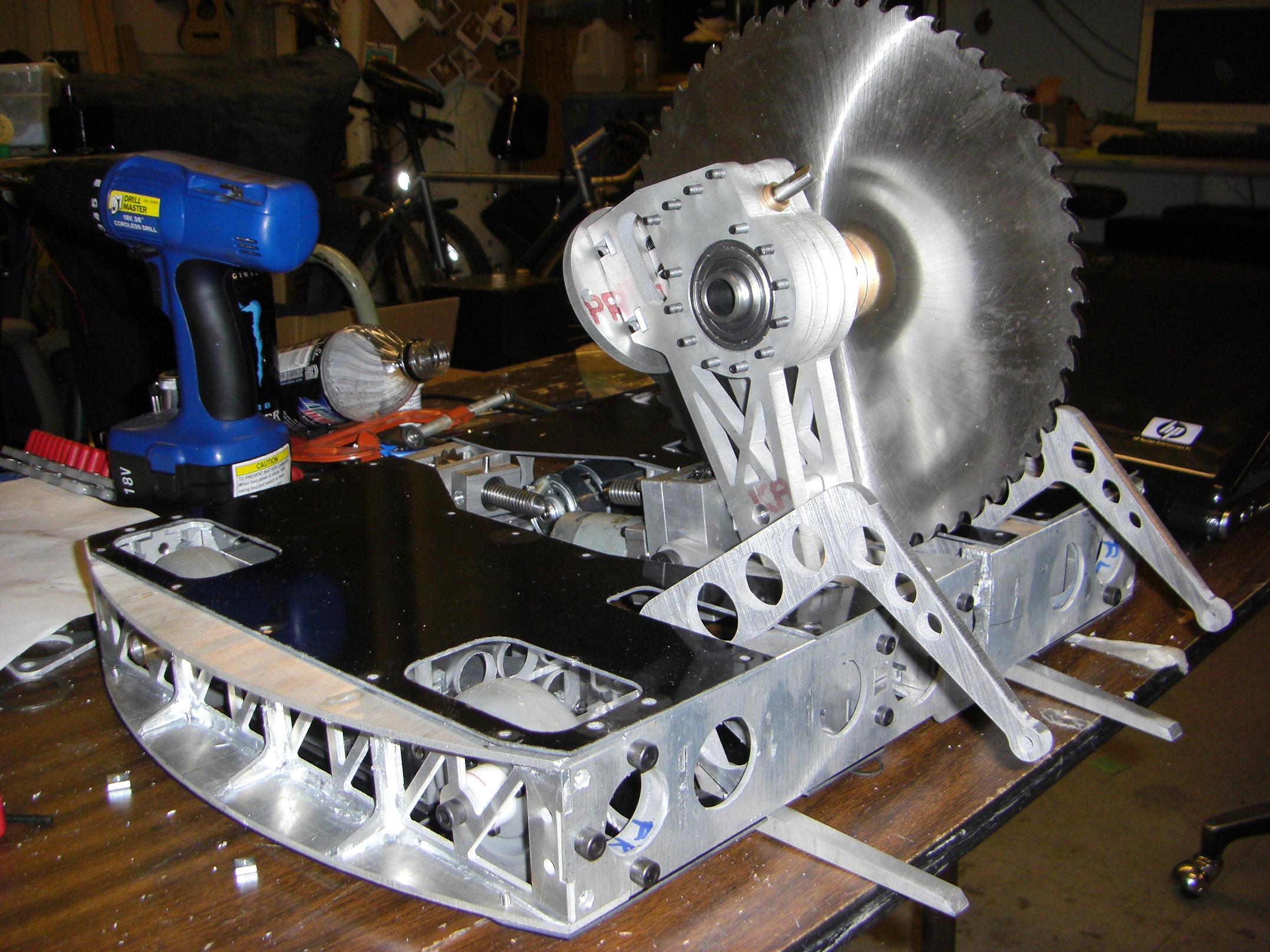
The Pretend-o-Bot from the other side. Deathrunner was still cooking at this point, so it’s not mounted.
Stay tuned for the next episode, where I recap all the events of…
… yesterday.