The event, that is. Not the robot.
With term now well under way, the time I have to actually work on the robot has become more limited. Fortunately, there’s not that much grunge fabrication left to do on Arbor. It is, however, nowhere close to actually running. Major assemblies have been completed and most of the remaining tasks are just connecting the dots. Pictures of the dot-laying itself are below.

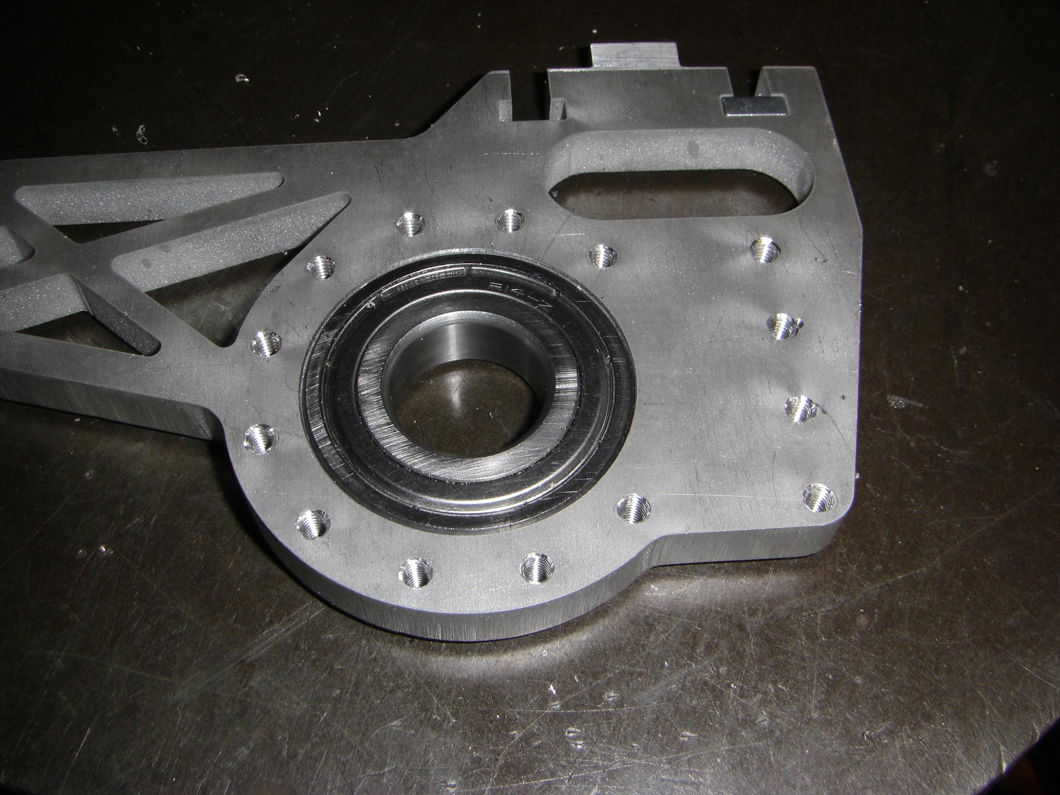
While waterjets are good, they’re not perfect, especially for sub-thousandths sensitive applications like ball bearing mounting. Ball bearings don’t like being compressed too much by interference fits – they get tight and a bit crunchy. Both bearing holes on the saw gearbox side plates were about 4 thousandths undersize, which is far too excessive for a press fit.
Normally this would be a simple boring operation to resize the hole, but it was greatly complicated by the fact that my brilliant design skills left no two continuous parallel edges to fixture to in a vise.
So the 85 pound milling vise had to come off. I elevated the piece on a scrap piece of 1/4″ aluminum and used that as a landing spot for the boring head. Otherwise, it was a smooth operation.
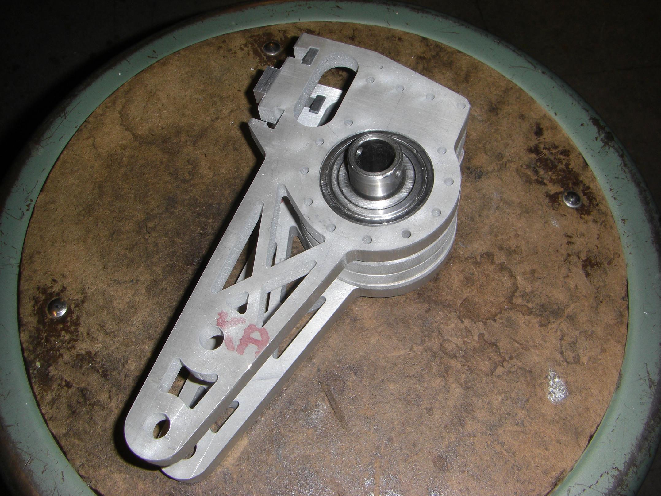
After cleaning up the bearing bore, I hopped on the 30 ton hydraulic press and slammed the bearings in. They are R14 double shielded ball bearings. Here’s the gearbox assembly just slipped together for visual effect.
I threaded the perimeter holes for a #8-32 screw. This was actually a hackaround for my neglect in laying out the 2D file for the threaded vs. nonthreaded side.
The threaded side, obviously, was designed from the outset with smaller pilot holes. Unfortunately, they all ended up the same size, which was a #6-32 clearance.
To remedy this without using nuts, I had to slightly enlarge the holes in the other gearcase parts and then use the existing #6-32 clearance hole to tap a #8-32 thread.
I fell into the trap again.
Remember a little while ago when I discovered that my 3/8″ (0.375″) aluminum was in fact 10mm (0.393″) aluminum?
I forgot that again, and designed everything around 3/8″ plate. Problem is, that just won’t do for the worm gearbox, which needs pretty precise spacing and centering of the worm gear to properly mesh. So the solution was to shave down the middle plates of the gearbox, which determined the bearings’ axial spacing.
A quick trip with a fly cutter reduced the thickness of the middle plates to 0.374″. I was concerned that the setup was going to be unsound, since I was effectly clamping a ring between two flat plates, but things turned out fine.
Uh oh.
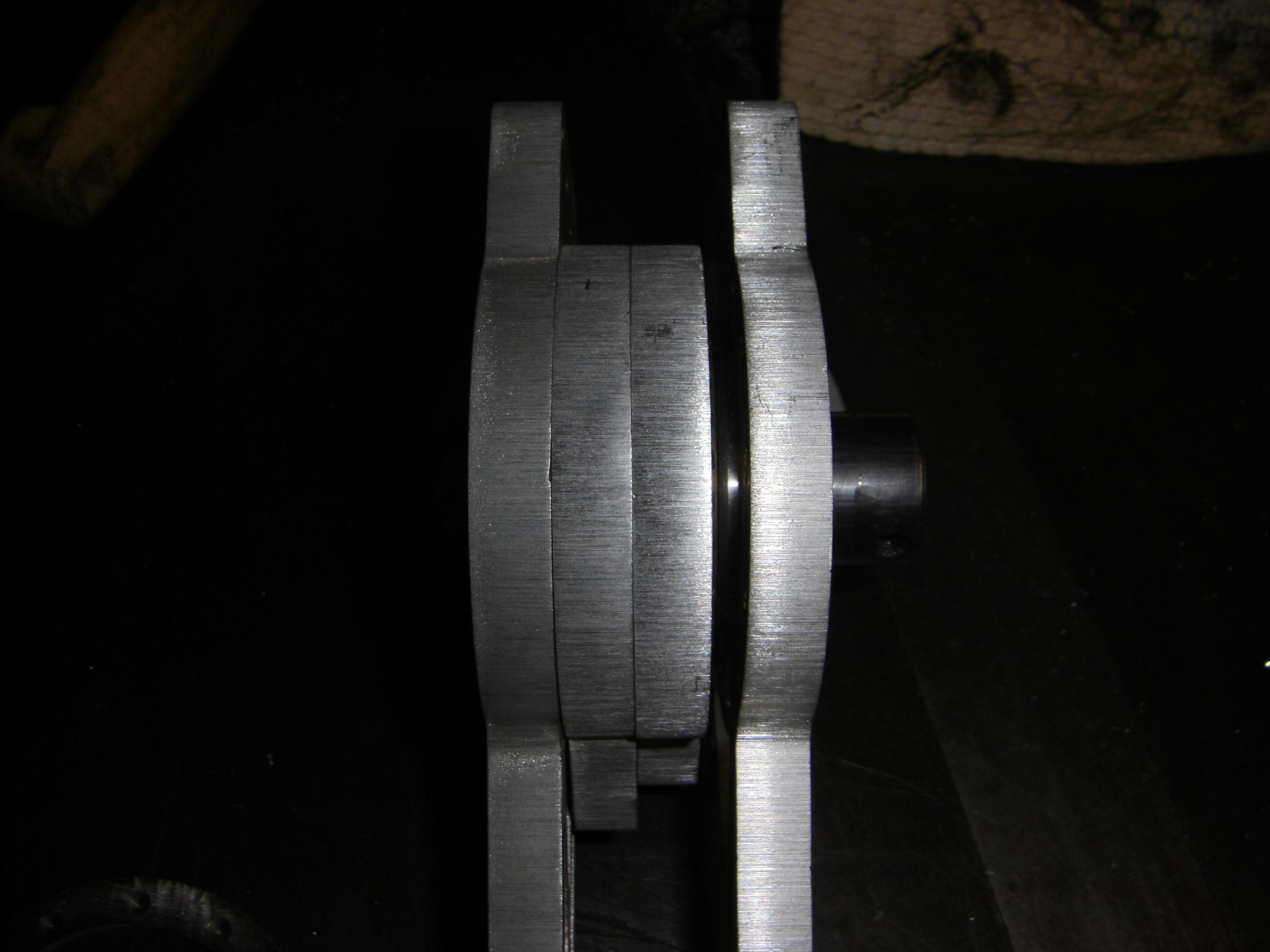
What you see here is the center plates failing to fall in line properly. There are a total of four plates between the two large gearcase sides, two 3/8″ thick and two 1/8″ thick.
There are three reasons for this happening.
- The 10mm aluminum vs. 3/8″ aluminum quandary. While I had fixed the middle two plates, by the time I discovered the discrepancy, I had already installed the bearings in the side plates, and didn’t feel like going back and uninstalling them. Additionally, trying to face down the side plates would have been an incredible pain.
- I reversed the bearing orientation relative to the worm gear. If you refer to the rendering of Arbor, notice that the ball bearings stick out of the gearcase side plates. This required substantial shimming of the worm gear between them, something that I did not account for when I placed my first McMaster order. To remedy this, I investigated reversing the side plates so the bearings pointed inwards. Each bearing then should have needed only 0.025″ of shimming.
- …if the aluminum plate was actually 3/8″ thick. Nope. The difference between 20mm of aluminum and 3/4″ of aluminum is about 0.04 inches. So, the interior of the reversed side plates were already 0.04″ too close. Now, while the two 10mm plates in the middle would have offset that and made things work again, I already cut them down to 0.375″. That means there was about 0.08″ less width than there should have been: for a grand total “leftover gap” of roughly 0.16 inches.
This meant that the two 1/8″ side plates couldn’t be installed.
I sat there scratching my head for a little while before deciding to just keep shaving the 3/8″ plates down until they accounted for the discrepancy. They had to be symmetrical in the middle to fit the worm shaft between them, so I couldn’t just use one or the other, etc.
Each side plate ended up at about 0.330″
All said, this took about 0.08″ of width off the whole assembly. Fortunately, the design is flexible enough to accommodate that change.
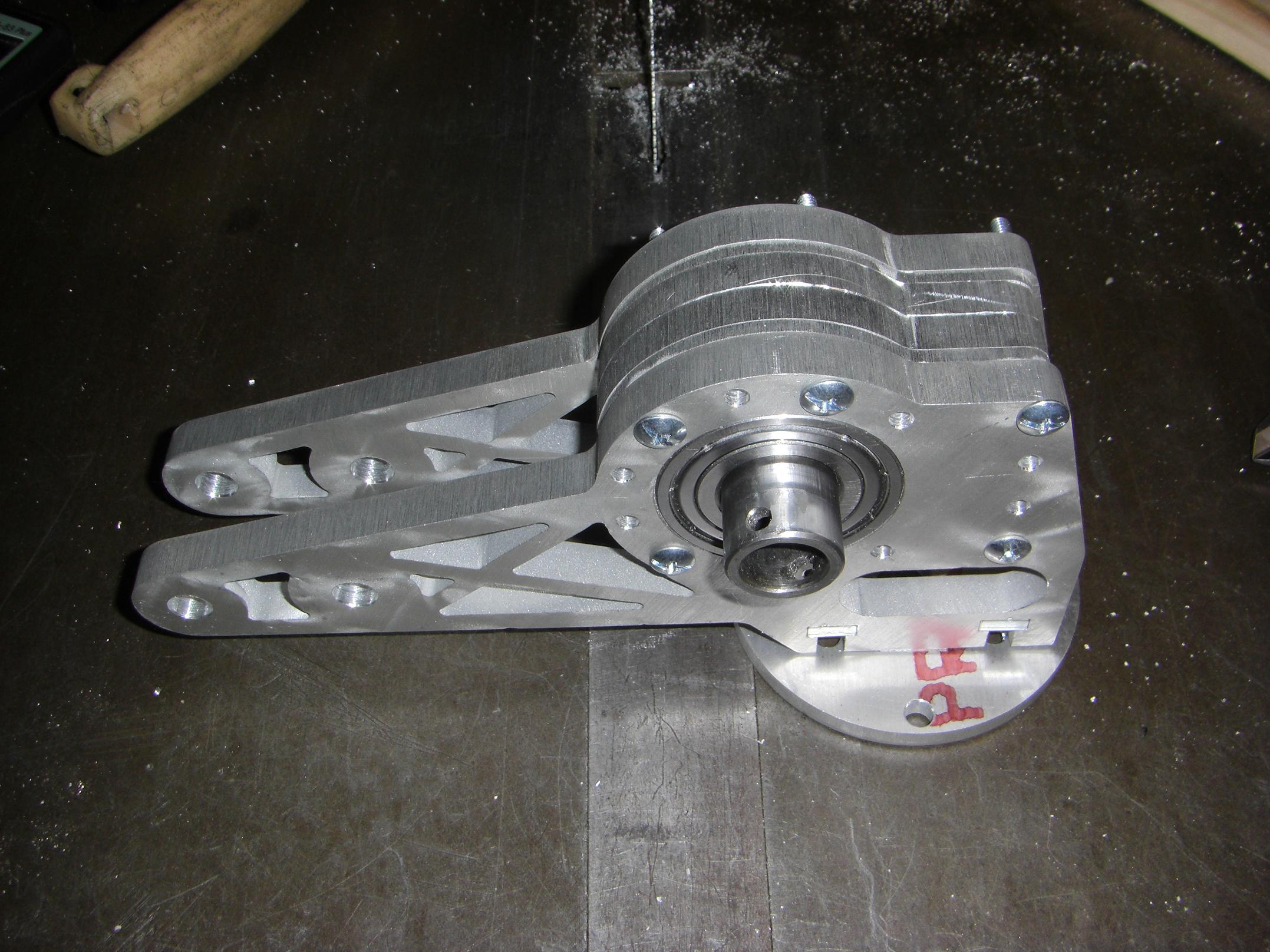
Here’s the first bolt-through of the entire worm gearbox assembly. I couldn’t locate 2 inch long #8-32 screws, so some dinky philips head deals had to take their place for now.
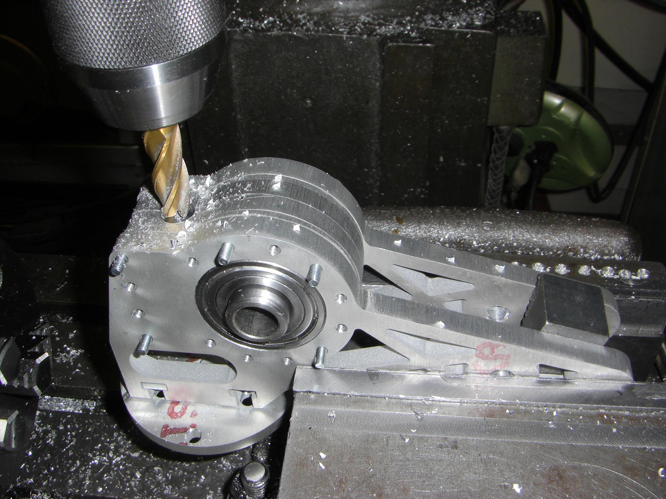
While everything was bolted together, I decided to bore the worm shaft hole in situ. I just stuffed the whole gearcase into the vise using a step block between the “ears” to hold the pressure, then drove a 0.5″ cutter straight through in the appropriate location.

Observe, the worm gearbox. The way the worm shaft is installed is slightly nonconventional. Each center thick plate has half of the 1/2″ hole in it. These envelope the 1/2″ shaft bushing that is stock to the worm gearbox. The rectangular extension of the gear casing is exactly the width between the thrust bearings of the worm shaft, so it fits in snugly and is captured both axially and rotationally.
With the worm gearbox essentially done, I went back to work on the other subassemblies of the robot.
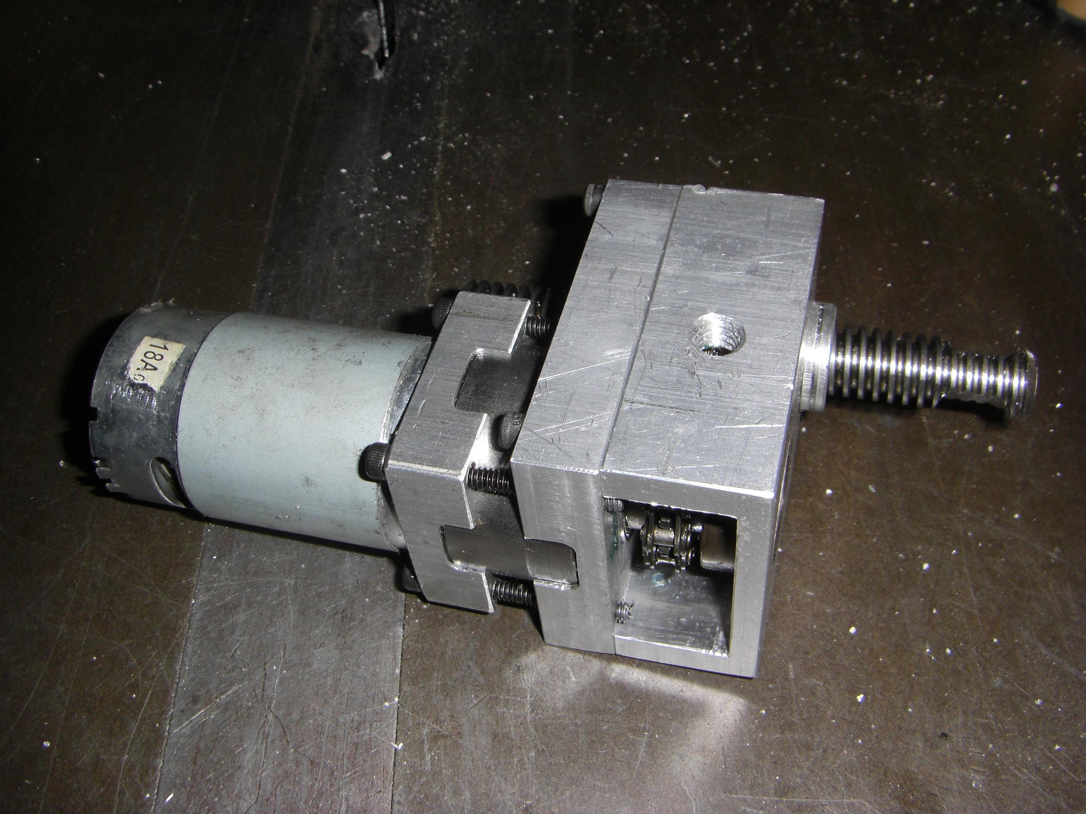
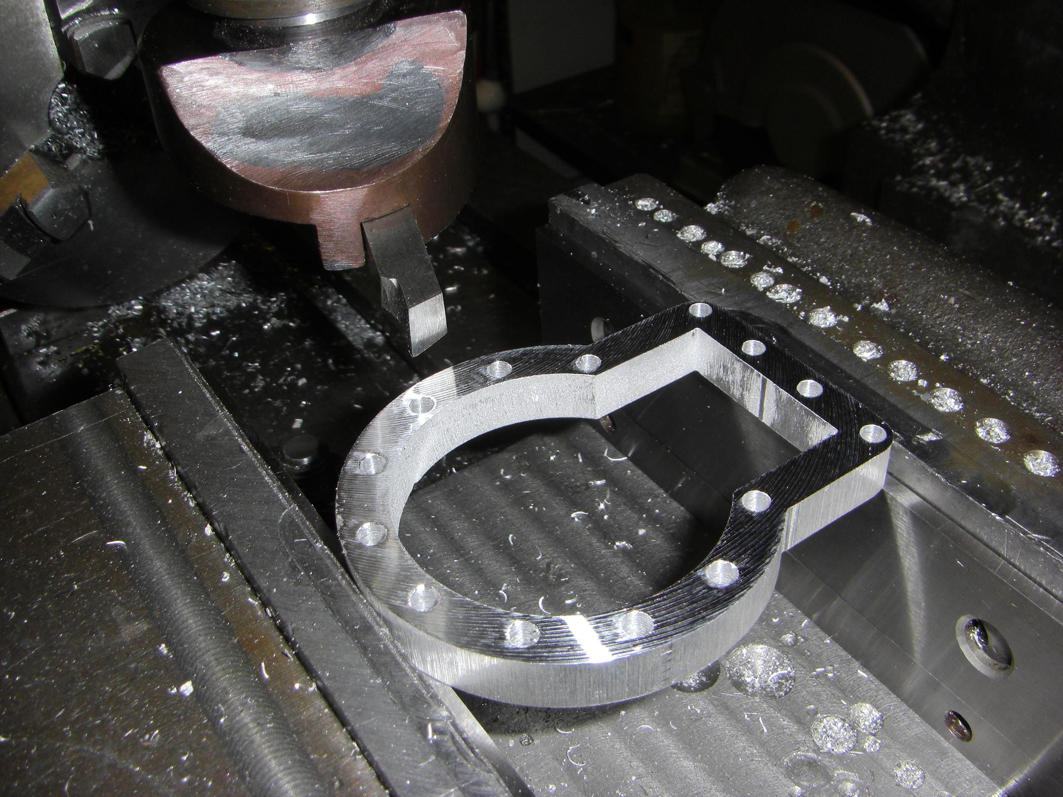
Here’s the actuator of yesterupdate, but linked with chain and filled with gears. It worked like a dream after some selective shaving of material from the C-shaped output casing.
Essentially, using an even (14) and odd(11) tooth chain in the same powertrain will result in circumferential distances that are roughly one pitch too long or short. While they sell “half link” chain connectors, they don’t do half pitch ones, because those are physically impossible.
So, I was left with a chain that was just loose enough to occasionally grind and lock against the side of the casing because the chain links exhibited a limited amount of cam action.
Well, that isn’t any good, so I stripped off some of the wall thickness where the chain tried to bunch up. Problem solved.
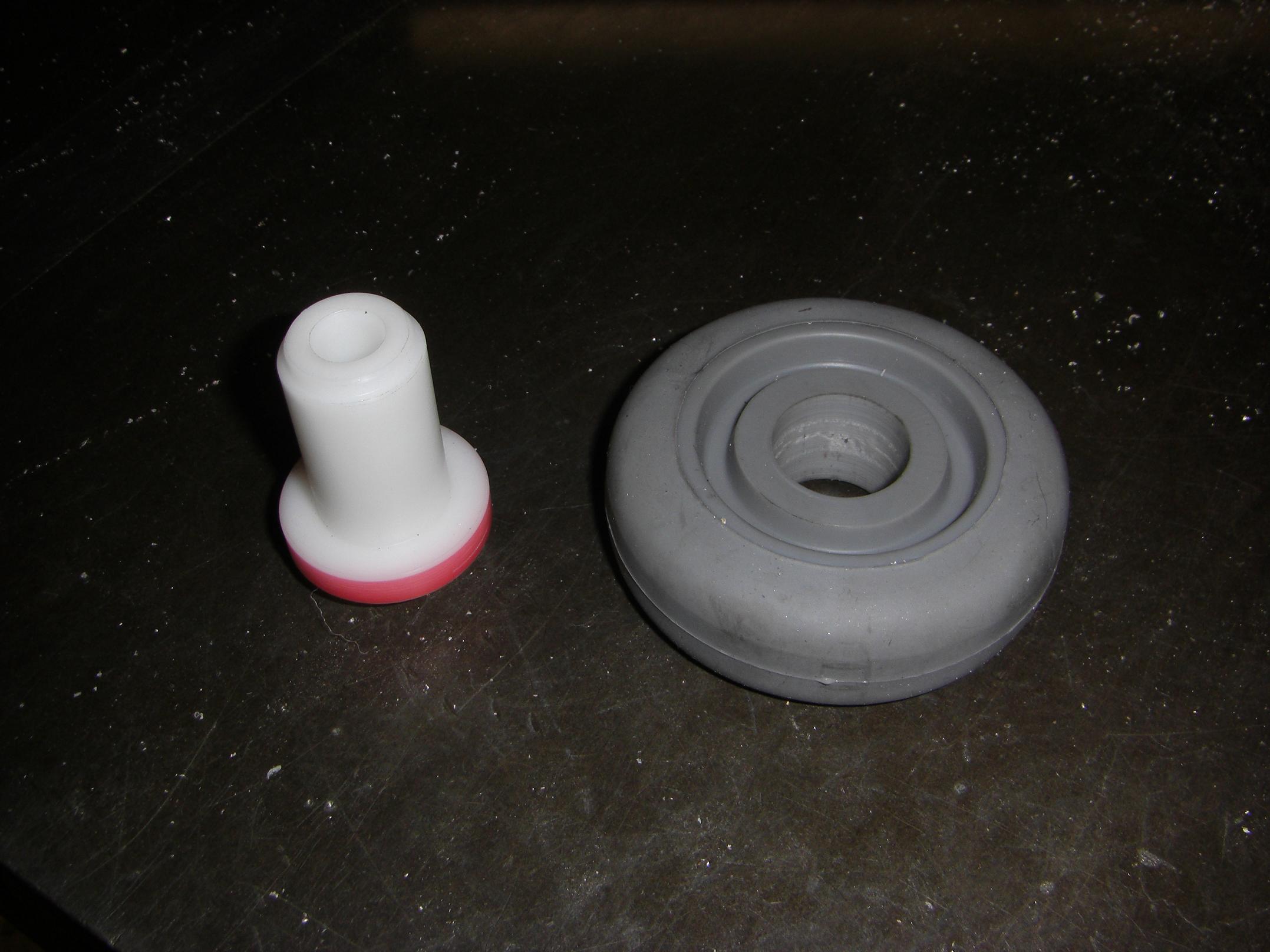
I knocked off more protoforms of the wheel hubs using Delrin. The front wheels won’t be taking direct torque from the motor, so I elected to make them from plastic to save weight.
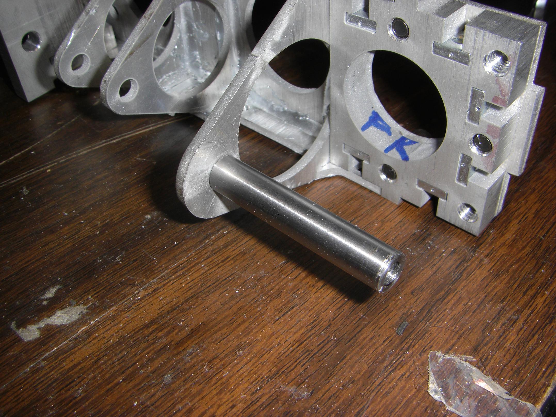
Using the leftover 3/8″ precision-ground 12L14 rod from Überclocker (the one that machined like aluminum), I popped off most of the small standoffs and dead axles in the design. Most, because I haven’t designed the rest yet.
I see where this is going.
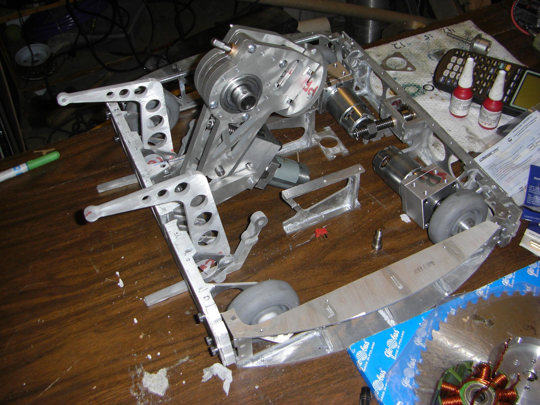
Here it is. The 100th build picture of Cold Arbor and…
… what IS that? That’s not even robot-shaped. That’s a Pretend-O-Pile. It doesn’t even qualify for Pretend-o-bot.
I need one more trip to the hardware store and some more machine love before the robot can “stand” on its own, so to speak. Then, I need to cut the cover plates and electronics mounting facilities.
No, I need to design them first.
This will end well….