So I’ve used alot of “improper engineering techniques” while making some parts due to either a lack of proper tooling, actual experience/training, or desire to take a few short cuts (teehee), so I figure I’d document them here. Mostly it concerns lathe work, since the milling machines I have access to are rather well stocked. A running list, which will be updated as I find new and more unsafe ways to make my parts, is here:
1. Counterdrilling. Obsolete since we got real center drills, but before that time, I managed to start holes with a countersink. The multi-flute ones have a symmetrical pointed tip, often with remnants of the ground flutes running to the point, so it was easy to dimple the part with the countersink in the tailstock. Then I used a small drill bit (usually 1/8″ or less) and piloted the hole. Then I enlarged it to whatever size it needed to be.
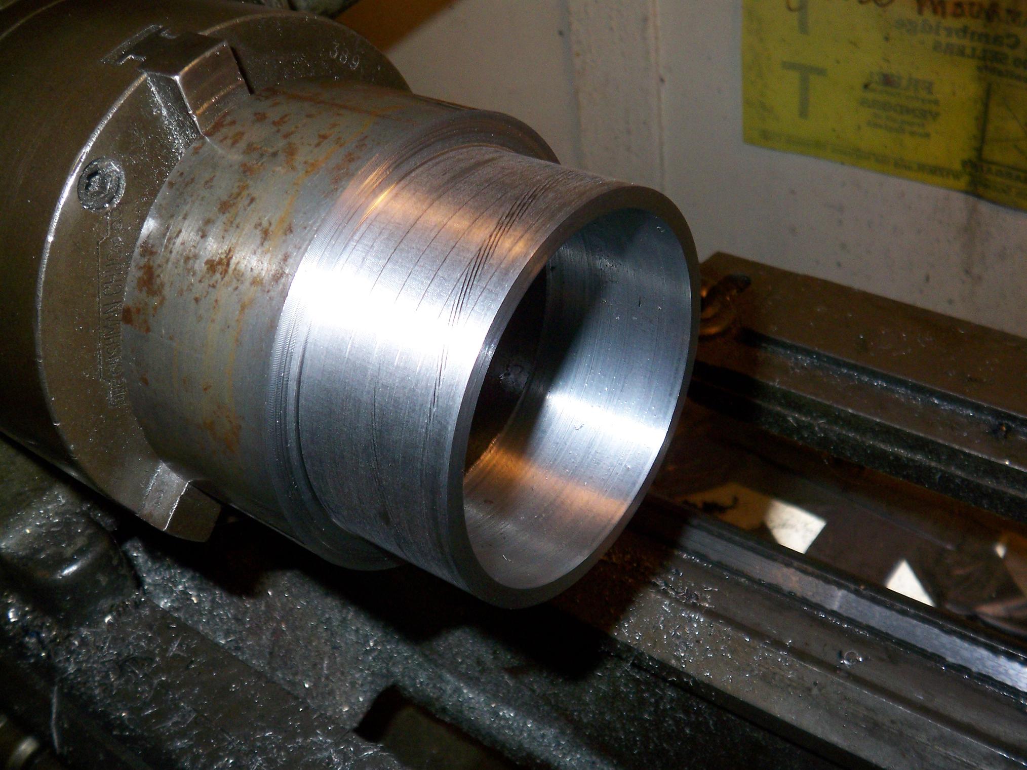
2. Not-Boring-Bar. We still don’t have a proper boring bar setup, so I decided to grind one from a stock carbide turning tool. It had its issues, but once proper clearances and draft angles were ground, it actually worked great. Due to the nonadjustable tool angle, some times I have to fudge with how the toolpost is set up to have it actually cut (or cut well and not just make a loud screech), but that would happen with a real boring bar also.
3. Steady rest centering. Since I never took an actual machine tool class, I’m not sure how the professionals get their workpieces all centered and true (past using a dial indicator and selective mallet bashing), but I found a bit of solace in the steady rest. Any time a piece sticks out more than half an inch or so, I can squeeze the thing in there and center the piece. First, the chuck is tightened lightly, enough to not loosen when the spindle is turned on. Then the spindle is fired up and the little jaws of the steady rest are cranked down until they just contact the material. This almost always makes the workpiece run (decently) true, but I have to be careful not to push too hard with one, or else it will cock off to one side. Then the chuck is cranked all the way down, the spindle run again (to see if the aforementioned fault did occur), and if it’s good, the rest is removed and machining begins.
4. Amputee’s Cutoff Tool. The lathe doesn’t have a cutoff tool setup either, so the proper technique is to make half the part, hacksaw it off, then flip it over and make the other half.
Yes, that often means maniacally wielding a hacksaw with your arm hanging inches away from a giant spinning round thing with protrusions and a bunch of pointy steel bits. I’ve been told that other people cut further away from the chuck to avoid dismemberment, but I don’t have that much material to spare. Moving the saw back and forth does speed the cutting, but often I can hold it in one place and keep it there until it cuts through. Moving the carriage with the tool bit mounted close to the line of cut helps keep the saw steady.
Yes, the spindle is on. No, I probably won’t be allowed near any machine tool in the student shops again if the instructors read this post. No, MITERS does not have a portable trauma kit.
5. Differential gear oil mixed with automatic transmission fluid, knife honing oil, and some WD-40 actually make a pretty neat cutting lubricant mixture. Gives beautiful finishes with a slow power feed (that I subsequently smudge when I take the piece out). Just plain WD-40 also works, and has the added upside of making huge smoke clouds on large diameter parts which I use to frighten new MITERS members.
6. Face-drilling. No, this does not involve using my face to drive the drill bit. Due to (again) the lack of a cutoff tool, I find it easier and safer when working with small diameter rounds to take a giant drill bit and just drill down the round stock to the dimension needed. A slight waste of stock, but if I size the stock right, wouldn’t matter anyway. The picture linked was me drilling down a 1/2″ bolt to make the Extend-O-Shaft 2000 for TB4.5.
7. Ghettoedging. One of the only techniques I had to use on the milling machine before I 1) found the edge finder at the Media Lab and 2) got edge finders at MITERS. The technique is simple. Color the edge to be located with a Sharpie marker. Then load up your favorite endmill. With the spindle running backwards, slowly feed the material in, and stop as soon as the first bit of sharpie disappears. Raise the endmill by the quill/column/whatever suitable Z-axis part, account for the tool radius, and start on the next edge. Don’t forget to run the spindle right way when you’re done.
It worked great on the ML’s junky import mill-drill, since with every tool contact there would be loud vibrations through the whole machine (and the… filing cabinet… it’s sitting on). With the giant Bridgeport at MITERS, it was alot harder, since all the cast iron and concrete floor would absorb the tool vibrations.
8. Ghettocentering. Combined with the Steady rest, it’s all I need to make true parts on the lathe (okay, true within reason). Drill bits have shanks which are usually the same diameter as the rest of the tool. Shanks are solid, round, and very close to the chuck, which is mounted in a stiff tailstock. If I need to remove the part for any reason, I make sure to drill a center hole first (using as large a bit as the end part would allow). Then, when the part is replaced, I can slide it on the drill bit shank first, then clamp it down in the chuck. It keeps the part centered axially as well as radially (within reason). I can then follow up with the steady rest. Or, on occasion, I can manage both at once.
There’s probably more that I can’t think of at the moment, but rest assured that this post will pop back up on top if I break some new ground (or some parts, or me.)