Land-bear-shark: Now With More Tilty-sense Board (than it should have)

It hasn’t blown up yet!

(cue controller fire in 3…2…1…)

I spent most of today finishing the driving code that I half-started on Sunday night. Because the new board mounts do not have the microswitch to detect the rider, I was left with only the radio failsafe as a way to kill power. Before, an invalid radio command (or the total absence thereof) did not open the contactor, but that was changed to buffer that line of defense against runaway miniature tracked vehicles. Next, in a fit of i-hate-software-induced rage, I coded an asymmetric ramping function which took a master throttle command from 2000us to 1000us, with 1500us as ‘neutral’, and ramped it at adjustable rates to adjustable endpoints. The ramping was set up such that increasing throttle and increasing braking (both on the trigger channel of the transmitter) was ramped, but decreasing throttle or braking force was passed straight through.

LBS is practically impossible to ride without some kind of ramping or other controls damping, so I decided having this more complicated but tunable code would come in handy during ride testing. As an added bonus, the code is very modular – I could splice in the master radio command with the average displacement of the rider’s center of gravity after the load sensors are installed.

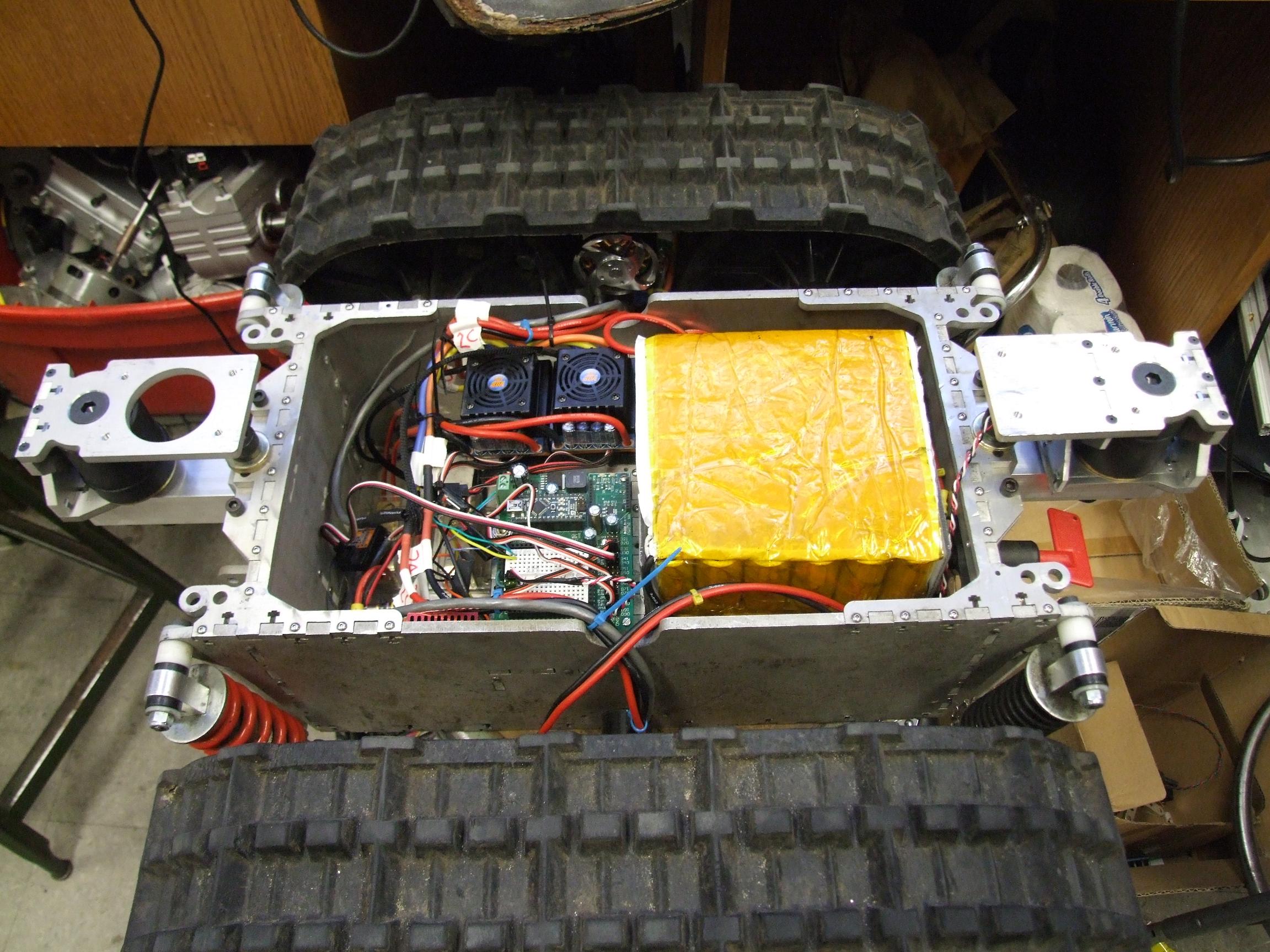
So this is what the whole thing looks like after finalizing the wiring with zip ties.

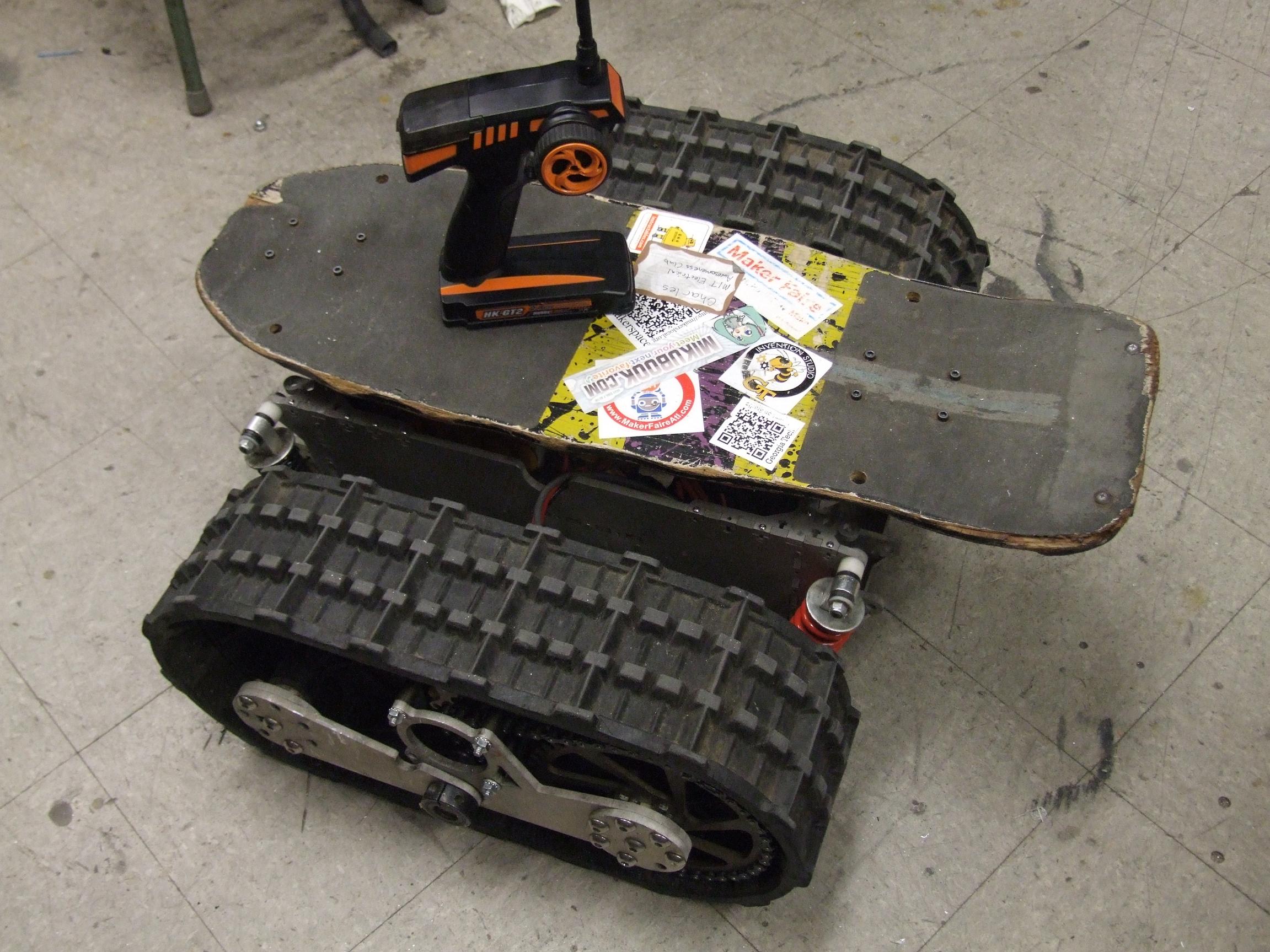
And with the board remounted. It doesn’t really look that different from the previous version, but it has more stickers!

Ride testing revealed that even upgrading to the 70A rubber bushings was not enough: the board is still too soft. They seemed to “loosen up” with repeated bending, too. Even worse, it’s very underdamped: Because there is no friction element in the joint (only the bouncy rubber bushing), it’s easy to trap yourself into an oscillation of full left and right tilt, resulting in a very quick destabilization as the tracks pulled left or right. This behavior was termed “latching” after the unstable behavior exhibited by malfunctioning amplifiers. Part of the fix is adding some rubber washers or other friction-adding element to the joint, but I do need stiffer bushings. Space is the most constraining issue here, since the mount was designed around the 2″ long, 2″ diameter rubber bushing mounts. I’ve thought about casting my own ~80A polyurethane ones, or making an extension of the joint which actuates gas springs.

I also discovered that ramping the braking force contributed to alot of “laggy” control feel – after turning up the gain repeatedly, the best results were obtained once I just pegged the ramp to full – that is, following the braking command both in and out as quickly as possible.

Otherwise, the optimized behavior of the HK cartrollers to R/C car racing (and not, say, rideable vehicle propulsion) showed through – starting in a sharp turn wouldn’t result in one side’s track braking, since by default the controller is designed to coast after it has detected zero motor speed. Only a small amount of forward throttle coupled with the turn would actually result in stopping one side. This is not something which is addressable in the controller’s calibration settings. Turning on smooth surfaces is still a little unstable, since these controllers are not actually “speed controllers” so much as just open loop voltage drivers. True speed control (even synchronous rectification) would guarantee a yaw rate because the tracks will be forced to travel a certain speed, and the faster cannot drag the slower to a higher speed. This is something which will be addressed in the near future.

At least they haven’t exploded yet – after all the testing, the cartrollers were reasonably warm, and the SK motors burning hot. It was all on flat ground, however – going up the wheelchair ramps here would probably make the cartrollers unhappy. The first burnout was most likely due to very high current spikes because the sensors were totally off. I would trust the 150A version of the cartrollers much more in this application.

What’s more important is that I get this thing on a more slippery surface and run it around before determining that all of these are shortcomings. After all, real ATVs and tanks aren’t tested in parking lots; they’re tested in rough terrain. The brushed drive worked just fine in the grass at Maker Faire, but was almost impossible to handle on-road.

Enough rambling. I know what the Intertubes wants to see:


Land-Bear-Shark: I’m getting closer to blowing it up again

I’m starting to run out of things to work on to put off the software, which would require a substantial rewrite in order to change the signalling protocol over to R/C servo style PWM to accomodate the Hobbyking cartrollers. In the end it will be simpler, but still…. software. That’s only things that closet electronics engineers do. Otherwise, I’m taking so long on this that my load cells are probably going to arrive before I wire everything back up, but perhaps that’s just me subconsciously pulling towards trying to get that version working and skipping this steering-sense-only stopgap solusion. What I’ve also discovered to my potential dismay is that the HK cartrollers will just explode as soon as I actually get on the thing, so maybe I should start making room for the Kelly controllers again, or have another solution on hand…

Decisions, decisions. And pictures:

Speaking of closet EEs, check out these sensor holder boards by Shane. I’ve been meaning to make a clean, permanent mounting solution for my Hall sensors for a while, but just Never Got Around To It.  These are external mounts – they face inwards into the can, and the slots make for adjustable timing (also addressed in that post, and an interesting read for anyone else wondering why their motor doesn’t reverse).

Normally, I’m a fan of the internal slot-mounted sensor. For the SK motors, though, I would have had to mount them outside the motor because the slots are too narrow, so I got to test drive these mounts first.

Boards are nice, but that still doesn’t change the fact that the motor mounts I built have no provisions for attaching the boards. That’s fine, I’ll 3d print a little mounting ring thing.

Originally designed with 3 notches to fit the sensors by themselves (without a Nice Board), this mounting ring is aligned by the conical portion of the motor face, and protrudes very slightly past the end of it. This means when I tighten down the motor mounting screws, the ring is firmly secured by a taper fit. The whole thing is actually capable of rotating for sensor timing – with the sensor board’s mounting slots, it’s a bit redundant. A notch in one end lets the motor wiring through, and the two holes in the top face secure the sensor board.

Make-a-Bot is now on its last meter of ABS filament. Uh oh…

Sensor board attached and wired. I found some Nice 5-pin Cable that had a tension strand and braided shield. It’s a bit large and overkill for the task, but hey, 5 pin cable.

On the other end of the cable, I spliced in a standard R/C car motor sensor cable (ROAR 8.8.1.3 standard) I picked up with a Hobbyking order.

The next step was to test the motors. Because I don’t know if the sensors are actually in the right position or not, this was a game of applying gentle throttle to see if the motor would spin smoothly. For a fixed sensor input combination, there are 6 motor wire combinations to try, 2 of which work.

Hmm, well this doesn’t bode well.

I probably shouldn’t have tried to sensor-find on the full 22 volts. The SK motors have an internal resistance of like 30 milliohms, which means at 20-something volts, infinity amps tries to flow. If the sensor to phase relation isn’t correct, then the controller tries to flow infinity amps vibrating the motor around. The result is a literal popping sound as one leg of the power board detonates.

Luckily, I have a spare HK cartroller (the one that I took apart and beat up), but the fact that these exploded without even running the vehicle proper yet probably means it’s not going to end well. The motors are simply too low-resistance for a non-current-controller driver of this size to handle well.

After this, I decided that sensor finding on 11.1v might be better.

With the sensor-phase combo “found”, I timed the motors by measuring the DC current draw while rotationally adjusting the sensor mount. The point of optimal timing in one direction is represented by minimum current draw.

As Shane found out, optimally timing the motor for one direction using sensors like this does not mean they will be good for reverse at all. Due to a combination of factors such as sensor hysteresis, motor magnet field leakage, sensing distance, etc. the timing in reverse will be very far off – as much as an entire sensor state.

This means LBS will be able to reverse using the HK cartrollers, but very rudimentarily and only with extremely high current draw due to the non-optimal timing. This probably just translates into more death for the cartrollers.

Once the Band of Optimal Timing was located, the sensor mounts were fixed in place by tightening the motor mounting screws.

After wrapping the whole package up and potting the sensors to make them a little more waterproof, it was time to mount the motors.

Hey, that’s an awfully small sprocket isn’t it? I didn’t know that they made things such as 6 and 7 tooth drive sprockets until I actually looked. The SK motors have a much higher torque constant than the CIM motors of yore, so I could bypass the CIMULINK reduction and just increase the single stage chain drive ratio by using a smaller sprocket. The motors have a RPMs-per-volt rating of 200 or thereabouts, so with a 7 tooth sprocket, resulting in a 6.4:1 ratio, the speed is approximate the same as the CIMs using the pre-reduction and 4.5:1 chain drive (about 18:1)

With the 7 tooth sprocket, the chain turned out to be essentially the correct length after I added a “halflink”, or one full pitch. There’s a small amount of slop, but it’s better than before, so I decided to not use a tensioner.

I verified that the motors were in fact still working after wrestling them into the track pods. After that, it was time to throw everything else back in. The batteries are in a different orientation this time – sitting flat instead of vertically side by side, and they have polycarbonate plates holding them from being jostled. Previously they were free to bounce around inside the cavity, which I can’t imagine was very good for them.

The next step is to Put The Arduino Back In and make some R/C based driving code – and detonate the cartrollers.