The Short and Tragic Flight of the LOLrioK…err… LandBearShark

Echoing a “short and tragic” test run of another vehicle, I managed to rudimentarily finish LBS using a wired control solution for kicks. It proceeded to fulfill that immediately by kicking me in the shins and running off, and is now the target of a 50-state man(bearshark?)hunt.

Well, okay, so it wasn’t that dramatic.

But also, only one half of that sentence was a lie.

I elected to try and get LBS running in time for the third Japanese TV show in three months to visit MITERS. Yeah – for all I know, I could be a Japanese media sensation at the moment and I wouldn’t know at all. Regardless, we are seen by the media production companies in question as some sort of… I don’t know, innovation or intelligence or amusement or something. All I know is it keeps involving crazily dressed people acting as reporters or correspondents.

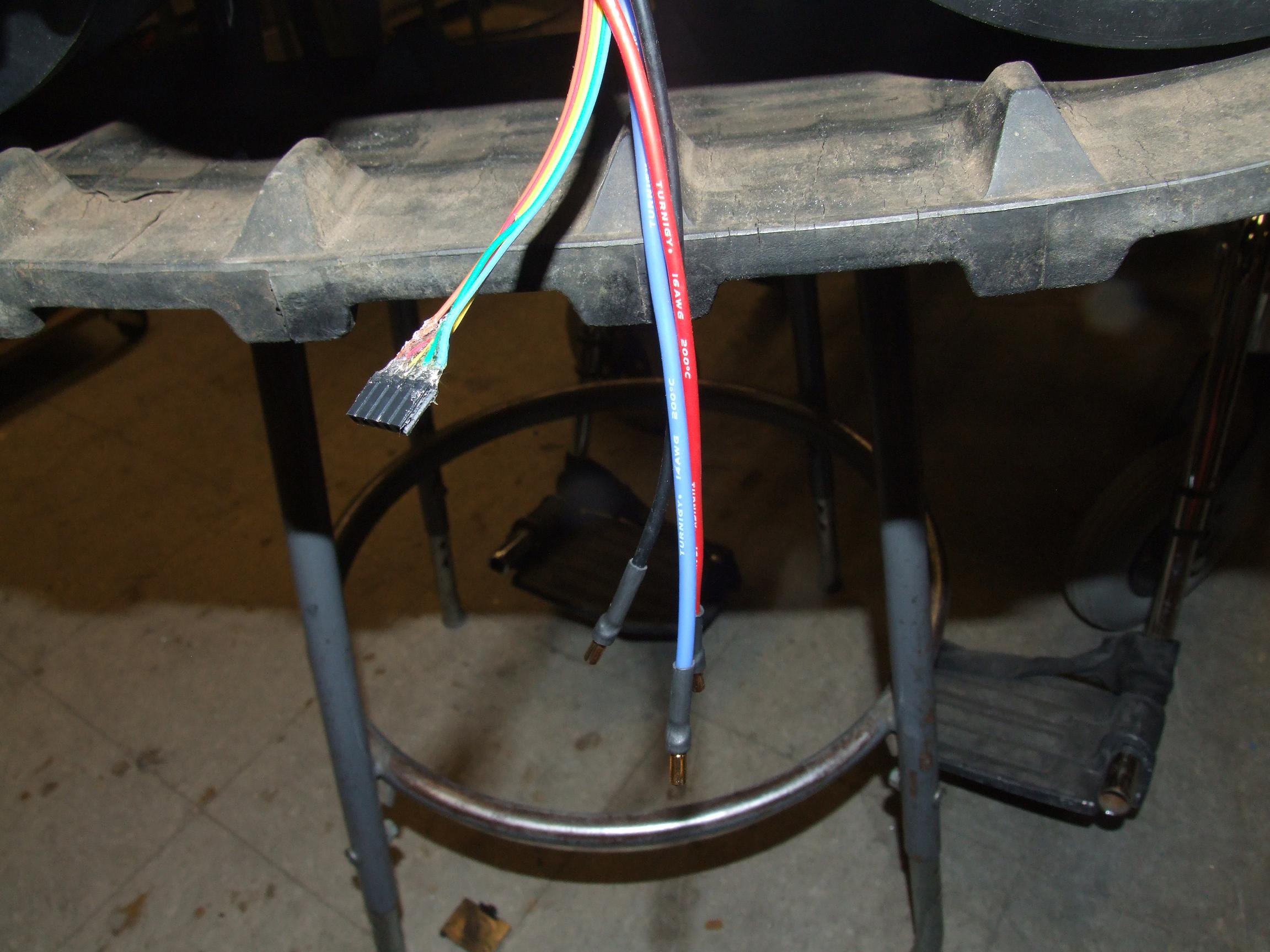
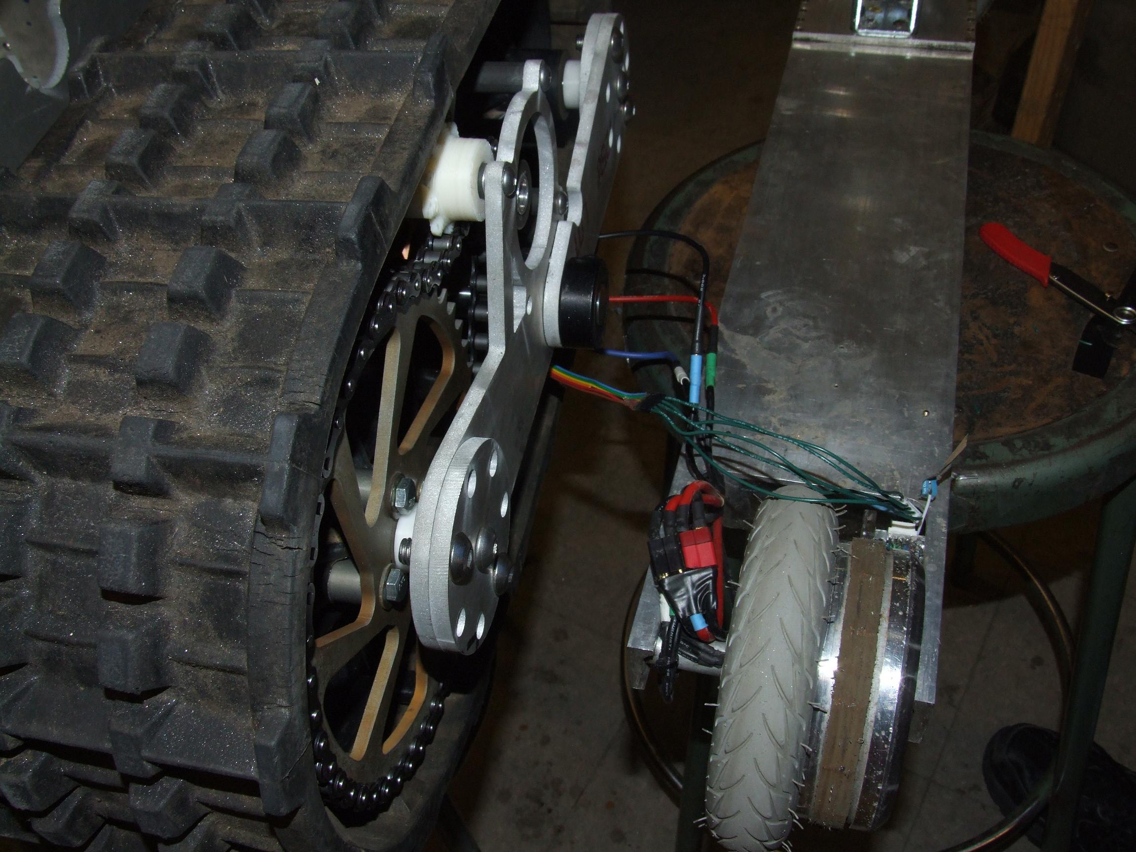
I elected to Just Beast It and didn’t really take many pictures of the process. Here’s the beginning of a veritable tree of Deans connectors. I kept making 3-way splitter harnesses only to remember that I needed two additional outputs, so had to keep making even more splitter harnesses. Most of the wiring gauge is small because LBS isn’t ever going to pull that much current anyway, and because I had it. The green packs were borrowed from Matthew’s Will Be Finished Some Day scooter build.

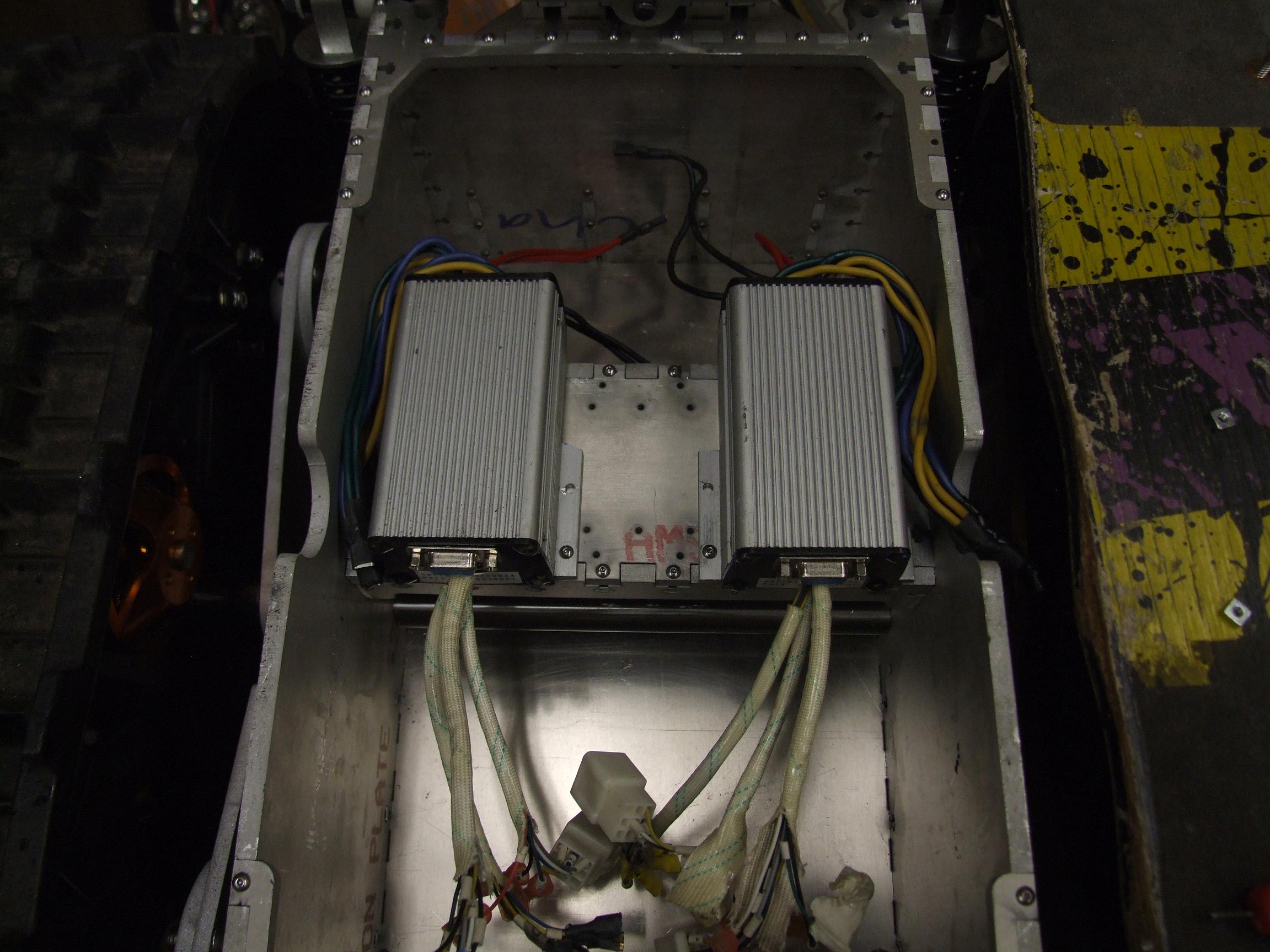
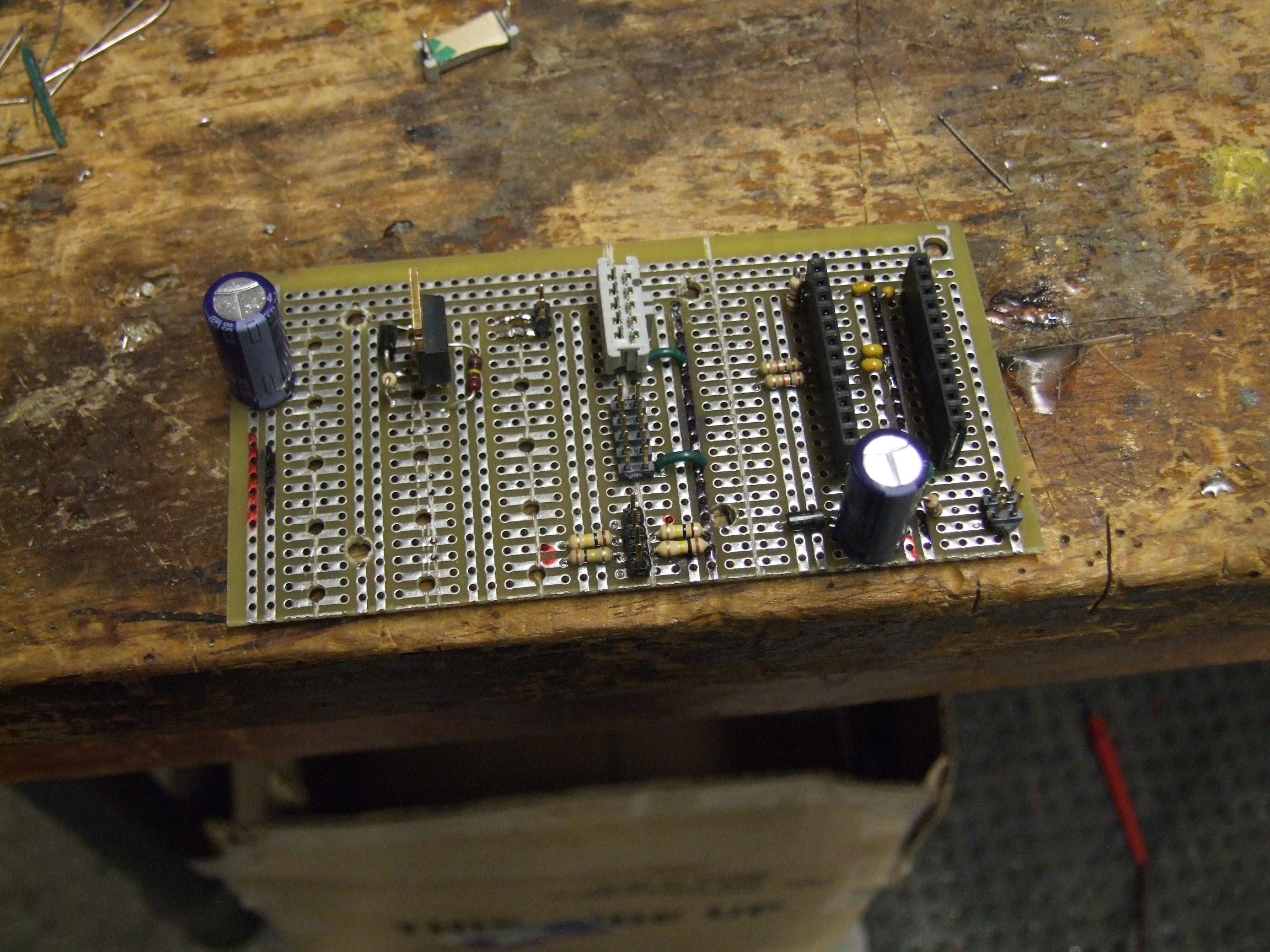
The Provisional Melontanktroller board was completed and mounted in the center between the two Kellys. I broke out the multitude of half-stripped and crimped signal wires on the Kellys to a single 10-pin IDCC header (which I don’t have an exact matching socket for, but whatever). The major analog and digital inputs, as well as the two status LEDs, have pins on the header. I decided against running controller power through the same header since that would entail someone connecting full battery voltage to the board, which I felt like would have been an impending disaster.

The controller for the time being is this totally rigged Arbotix Commander. So this thing is pretty much the most useless thing ever made, just by itself. It has no serial or FTDI breakout at all, and the only way to program it is through the 6 pin ISP header. It’s also supposed to be Arduino compatible, but without USB hardware, there’s really no way to put the compiled sketch onto it. Of course, raw Atmel assembly or C code can just be written for it, but… but but but.

So not wanting to deal with that at all, I just soldered wires to the joystick pots directly.

The backside will not be pictured since it’s too disturbing.

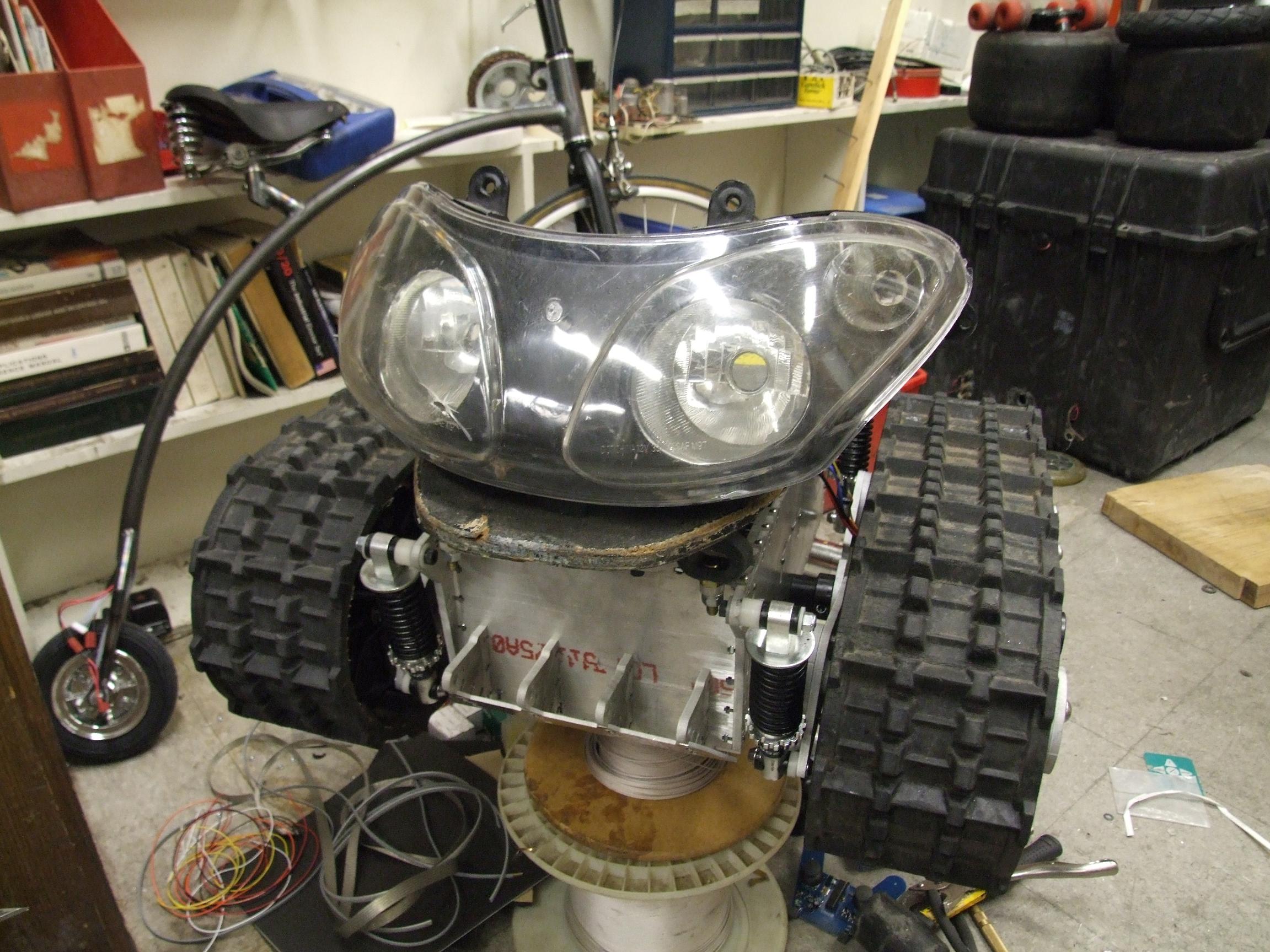
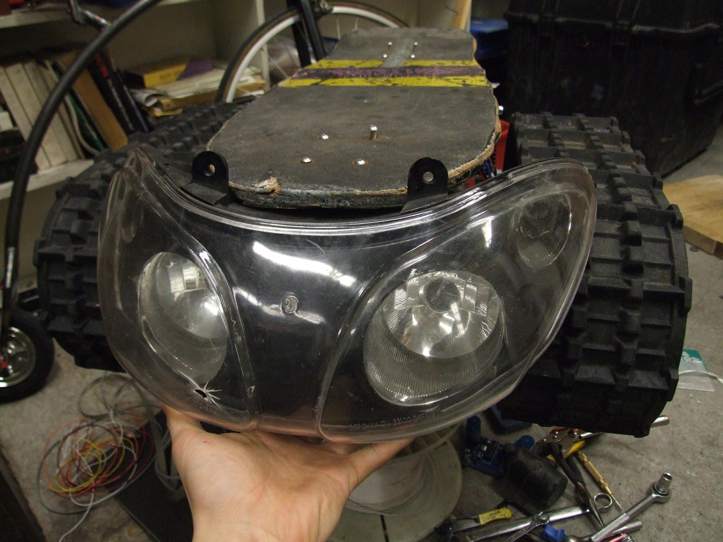
Okay, here it is: LandBearShark version 0.1 (beta). Happy?!

While nothing is clearly finalized, the (really) finished vehicle will not look substantially different, since the ninja-rigging was all internal.

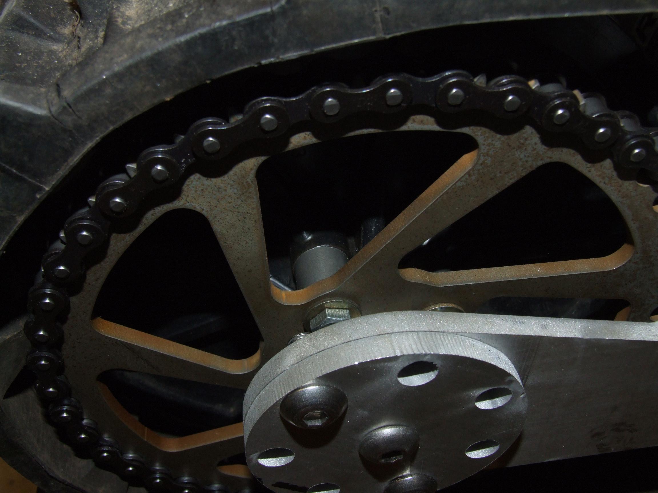
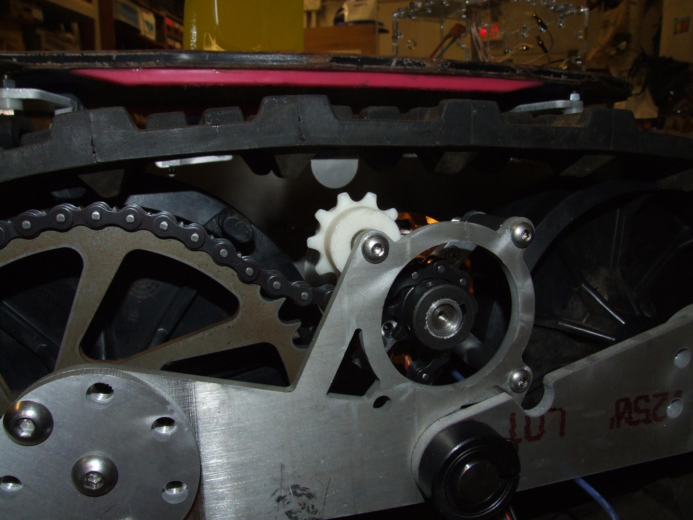
And a low angle view. The updated 11-tooth chain tensioners can be seen here, along with Segfault.

Finally, here’s what you might have been waiting for. Don’t worry, it’s not that dramatic.

MIT Tech TV

So besides all the awkward balancing, the version 0.1 design revealed alot of issues that need to be addressed.

  • The drive motor’s appended sensors appear to have very minor angular spacing errors, but that means every once in a while the sensor state enters [1 1 1] or [0 0 0] and causes the controller to throw an error. Only a small movement of the treads out of this error band will cause the controller to kick in. The issue comes from in-place turning where the motors have to apply alot of torque at zero speed, and can easily enter the error band without enough inertia to leave again.
  • The suspension is indeed kind of soft, and acceleration tends to rock the rider backwards. However…
  • …the Arbotix joysticks were just plain too sensitive. I didn’t write in any kind of throttle filtering or ramping, and the Kellys were configured for Beast It mode (i.e. very fast throttle ramping). A more sensitive and carefully designed signal processing algorithm is necessary.
  • A rider detect cutoff switch is absolutely needed. There was a brief (unfilmed) “Melontak rodeo” where I accidentally yanked the controller cable out and one side decided to start full throttling. Luckily, it was in a circle. While I could have used one of the switches on the Arbotix controller as a “dead man’s switch”, I couldn’t quite figure out how to code the state machine that would wait for one second from switch release before disabling the controllers (to act as button debouncing and to account for airtime or jumps)1, because fuck software.

I’m actually considering either switching LBS to brushed motor drive (eww) or going to a high speed but pre-geared brushless motor – possibly even stock 80/85 motors with a 4:1 planetary gearset or something. That, or find a motor with more slots and poles. Either way, the idea is to minimize the error band that is introduced by me placing a sensor in sideways or something – the gearing would ensure that the motor has more ‘wiggle space’ where it doesn’t have to apply significant torque to move the vehicle.

And a brushed motor drive (eww) would of course eliminate that completely.  But that’s the practical sissy way out.

Sharking Into The Future

I’m proud to say that the LandBearGryllsMelonSharkTankWeek is now completed with the exception of electronics. Which is really to say that I’ve finished another dumb aluminum sculpture and have reached the end of the design assembly file, and will now proceed to make things up as I go. It also means I strongly risk finishing it next year, or never at all.

So, the last time when I put the chains on after knocking out the motor sprocket adapter, I discovered something terrible but not very surprising. Namely, the distance at which the chain sprocket is mounted from the face of the track sprocket, combined with the absolutely terrific (in the classic meaning of the word) molding quality of said sprockets, meant that the chain would simple get jammed by one of the protruding track sprocket tooth things and lock the whole assembly solid. Now, having a tracked vehicle in which the tracks are immobile is about as cool as having a traffic cone – not even one with a blinky thing on top, mind you. So I made eight quick little spacers using aluminum rod in order to positively place the sprockets further from the track sprocket teeth.

I was trying to find a 1.5 to 1.75″ round of some slippery material to make a chain tensioner with when suddenly I realized that I had a 3D printer and so might as well print some damned idler sprockets. This idea worked splendid, but the first pass just used a copy of the motor sprocket, which was actually too small to reach the chain. How embarassing. Downloading and editing an 11 tooth sprocket model fixed the tensionless tensioner issue. I like this whole 3D printing thing.

Incidentally, during this process, I discovered that MaB’s extruder motor had finally broken down. The DC extruder motor has a bad reputation in the community because of its frequent and often mysterious failure mode where the terminal resistance drops significantly from ~30 to 40 ohms down to as low as 1 or 2, enough to cause the extruder controller to freak out and shut down… but it would still work otherwise. I temporarily bypassed this issue with a 10 ohm power resistor shoved inline with the motor leads so that the extruder never sees in practice more than 1 amp, which is well within the rating of the driver chips. It meant my test print came out slightly anemic because of the power penalty, but a temporary adjustment of the thread width parameter fixed it.

It also means I finally manned up and ordered a compatible stepper motor to build a stepper motor head with, because the software and hardware fully supports them now.

While contemplating tensioners, I added terminations to the motors. The usual 5 pin sensor connection and 3 bullet connectors for the motor phases goes on.

What does having the motors all wired up means? TEST TIME!

I ran a quick first run using the Kitmotter Demo as a commutation source. Even on the built-in 15 amp battery current limit, the track assembly turned smoothly and with a pretty decent amount of torque. I’d say the rewinding of the Turnigy motors to twice the number of turns and Wye termination was successful. Next, Shane wanted to see how much a difference his look-at-me-i’m-so-special-and-control-theory-minded sinusoidal field-oriented control motor driver would make over the cheapo square wave block-commutating Kitmotter controller. The resulting test video is below.

Note that while there isn’t a test video of the regular motor driver, the noise in either case was strongly dominated by mechanical sources… like the flapping chain and track belt.

Enough stalling and delaying the inevitable. It’s time to start on the electronics, and the first order of business is mounting the motor controllers (a very mechanical step, fortunately). These are the deprecated KBS36051s scrounged from the CityCar Graveyard. I don’t intend to use the stock something-or-other connectors that house the signal contacts; and half of them have been cut out anyway, so I’d need to make an interface board with some kind of signal processing onboard, probably Arduino based.

stopgap control solution

The final plan for LBS is to have a dual-hand wireless control solution similar to the glove control I have set up for the skates. However, I want to ride this thing sooner than that. So, for the time being, I’m going to run a wired control from a makeshift interface board to… I don’t know, two knobs or something. Here’s the beginnings of said interface:

I’m not sure where to begin describing it. It’s being constructed on the remains of half of a 6.131 class protoboard salvaged from the bowels of MITERS. On the right is the obligatory socket for the Mini Arduino. This style of protoboard really does not suit the point-to-point wiring method I’ve taken a liking to. Component placement here isn’t freeform due to the crossing rows of conductors, some of which I’ve had to slit to make space for more adjacent parts. So, I’ve yet to actually add wires – just trying to figure out where to put parts for now.

Anyway, on this board lies a contactor driving switch (second column from the left), the two Kelly interface connectors and throttle connection, the Arduino socket, and then at the very bottom right is the eventual rider-detect switch, which will just be two OR-wired microswitches read to determine whether or not I’m still on the thing. The idea is that after a certain delay of neither switch being closed (to account for shocks and airtime!), the throttle will be brought to zero and the contactor opened to prevent the vehicle from moving. The contactor would only block or conduct motor controller power, so the thing doesn’t turn off, but just Positively Stops Moving unless I ‘m on it.

I found some 10-pin IDCC connectors for the controller interface, but really only need 4 wires on each – an analog throttle, a digital “enable” line, a reverse toggle line, and ground. But I had them, so they’re going on there.


AAAAAAAAAAAAHHHHHHHHHHHHHHHHH

What the hell? Is that some kind of cracked-out anime version of WALL-E?

While that’s a great idea for Halloween, it’s actually the headlight module off a cheap sports bike the EVT gutted long ago for parts. Some of it ended up in here, and a specific subset of that made it close enough to me such that I was able to pick it up and giggle uncontrollably. No matter how tacky and bubbly it looks, it’s kind of growing on me.

By the way, the stick with a wheel back there is pf.

Alright, so I actually think it looks better in this configuration. It looks like some kind of treaded insect.

I might not actually buy replacement headlight hardware for it, but I’m definitely going to design up some bracket to mount it on the front there because it looks too damn good (and by that I mean hilarious).