or, The Concise Summary of the Reasons why I Hate Everything about Electronics and Software and Therefore Do Not Understand Why I Insist
on Constructing Complex Electromechanical Implements Involving Them; A Memoir by Charles Z. Guan.
One day I will actually write a book on why I keep building custom electric vehicle components knowing full well that I hate electronics and software and that it always blows up the first …. few… times or is generally just a pain to deal with.
Alternatively, I could complain on the Internet and then go right back to doing what I was before. But before all that, a video.
There you have it. After the past week of rebuilding and debugging of the electronics, I have a LBS that…
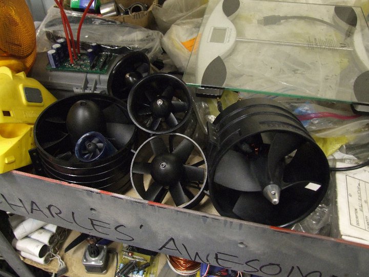
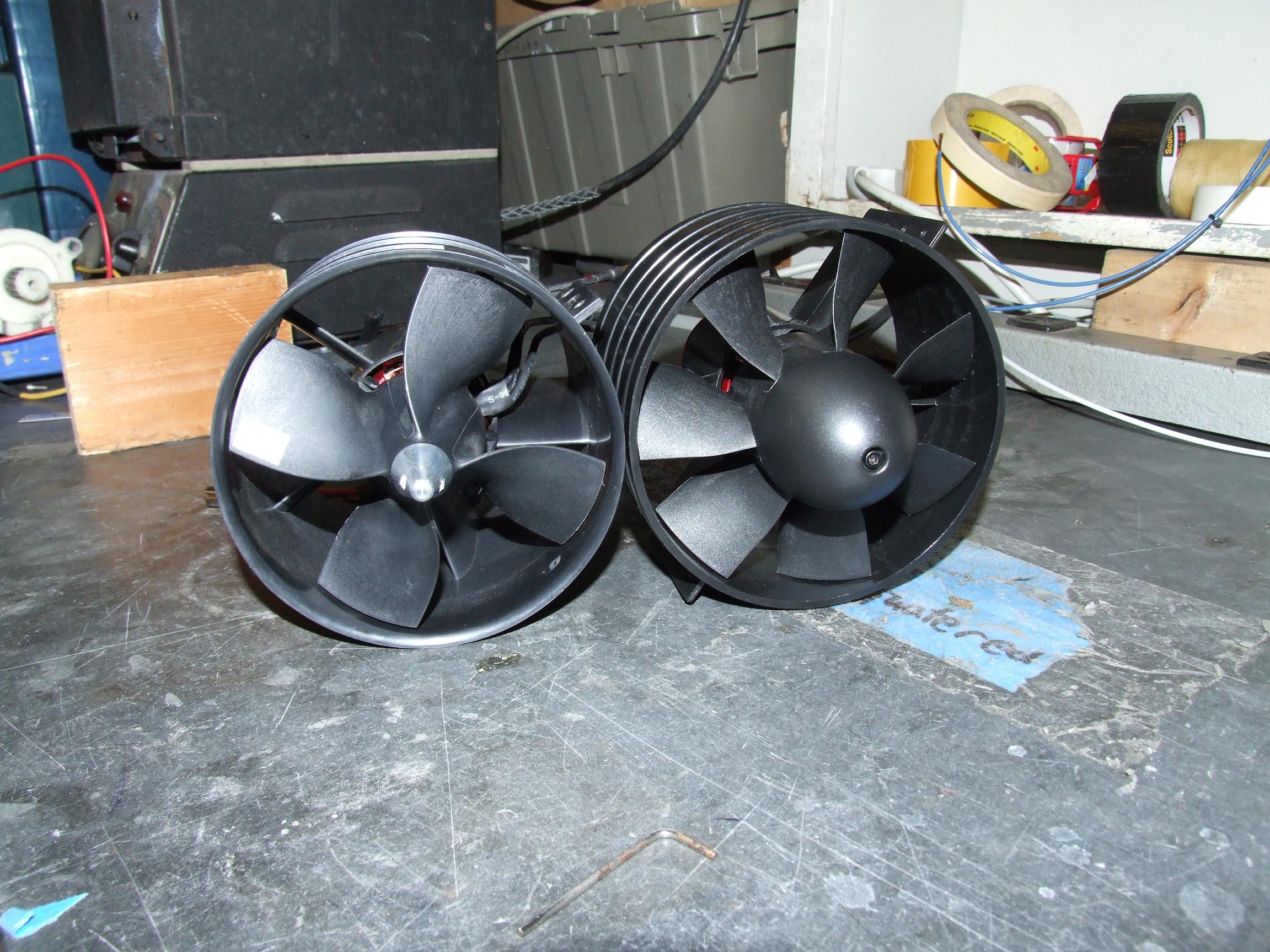
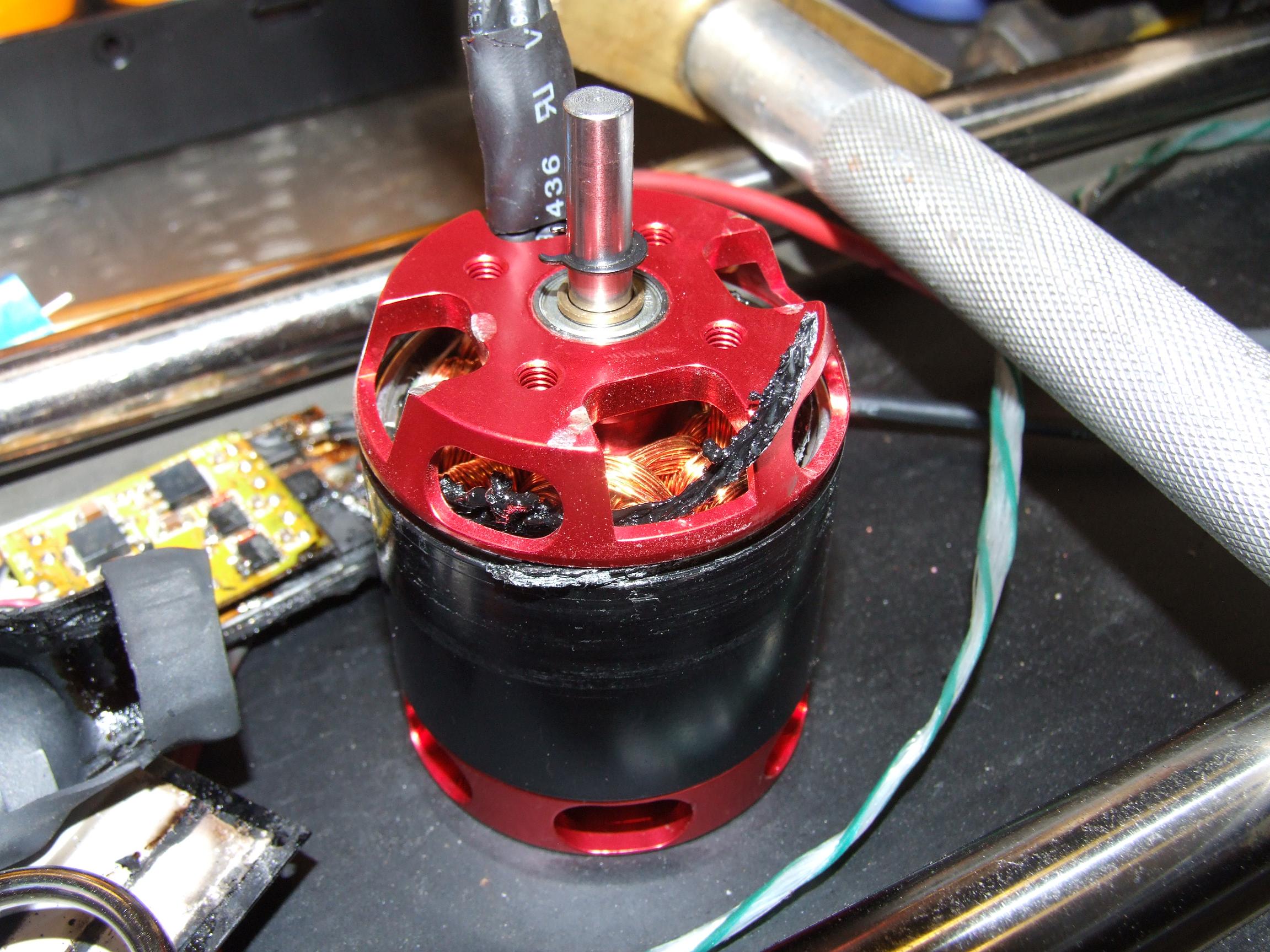
- Doesn’t use the Turnigy 80mm brushless motors like I said it would
- Doesn’t have the wireless hands-free controllers like I said it would
- Doesn’t go nearly as fast as I said it would…in fact about 2/3rds the previous design speed.
…so what did I actually build? I’m not sure, but it looks kickass and rather cute at the same time. It reminds me of some kind of miniaturize fancy construction equipment (you know like they make miniature cows or something). It’s very square and squat, the appearance complemented by the disproportionately large track pods…and honestly, would look at home in the MIT anime (I’m making one, I promise) as-is.
Last time, the Shark adventure ended with the motor controllers exploding upon application of power. Kind of reminds me of a certain other basket-case vehicle”s history. Not wanting to resort to just putting some Victors or something on it, I went ahead and made an entirely new board from my panel of 6 that I ordered, and being slightly more intelligent this time, tested it on a current-limited bench power supply first.
First runs of motor controller designs seem to either work, or explode spectacularly due to some fundamental error in judgement. I couldn’t get the new board to not dead-short the power supply. Any time the IR21844s were enabled, the boards would instantly become roughly 6-ohm loads and heat up quickly. 6 ohms? That’s a clear sign that FETs are turning half-assedly on, or half-assedly off, being unable to reach either the blocking state or the fully on, conducting state. Now, these controllers have already been live-edited once – I left out a critical connection in the current sense circuit, so I was checking for more unrouted connections and other signs of rushed board routing.
It was more useful to look at the schematic.

Unlike the Segfault boards, the issue in this case is what’s not connected. As in, the Vs (high side FET’s source) and M terminal (motor output, also known as the high side FET’s source) weren’t connected. This meant the high side can never really turn on… or turn off, or anything really. The gate might as well be left floating.
Great.
Well, at least this is an easy Little Blue Wire fix.

After verifying that, yes, the controllers no longer were power resistors, and that they responded to a PWM input with a proper output, and that my lack of attention and dismissal of EAGLE’s frantic cries of “YOU HAVE REMAINING AIRWIRES!!!” had done me in once again, I installed the controllers back into LBS. I decided to take the more cautious route and test everything on a power supply.

This is where the three hours of software nightmare began. Using the crude motor actuation code I made last week, I was able to get the motors to move forward and backward, not under radio control. This was just to verify the operation of the controllers and make sure the current sensors were working.
I began writing a more sophisticated driving program that took inputs from a handy R/C car radio (the HK GT2 if you’re interested). The first program was very simple, just taking the servo pulses centered about 1500 microseconds and linearly mapping them to motor PWM values… about a bone-simple as you can get. Hell, even people in 2.007 managed that one. I even taught people in 2.007 how to do that. It also read the status of the rider-detect switches and latched the contactor accordingly. This was one thing I wanted to get right, since I wouldn’t want my rideable 2.007 robot to run away.
But no matter what, I could not get the motors to respond reliably. The contactor would latch and unlatch unpredictably, the motors would twitch and some times lock on full speed. The ADC pin that the rider detect switches were connected to would seemingly turn into an output at will, driving the circuit low (and of course causing the contactor to open and the motors to stop). Then, it would randomly cut back on.The Arduino would frequently lock up, and the serial port some times spewed nonsense repeatedly until the board was reset.
Initially, I thought it was a grounding issue, since the 2.007 Arduino Nano Carrier has some limited protection features built in on its logic power supplies that could have been messing with system ground levels. I tried rewiring the board to run off a separate power supply, figuring that the contactor closing could have been introducing noise into the 15 volt supply that fed the board through the ground. I tried disconnecting everything at the advice of master Course 6 guy, and that pretty much ruled out any hardware being the cause of the problem as the board continued to twitch, reset, and lock up. The next step was to knock out functionality in the code, line by line, isolating the problem to one line of code.
Was it the math involved in processing the throttle and steering pulse inputs? Nope, with the exception of some possible variable typecasting issues, which were cleared with no impact on the problem.
Was it the multiple consecutive pulse reads that could have resulted in some weird timeout behavior? Nope. They did that in the class all the time and it worked fine.
Was it issues with Arduino built-in functions such as constrain () or map() and the inputs being incorrect or out of bounds? Nope, even reduplicating the functions explicitly didn’t solve anything.
And finally, after commenting, correcting, and deleting just about everything, we arrive upon the last line.

LMOTOR and RMOTOR are constants that designate digital output pins, and ICMDx is the byte being sent to the PWM times on those pins. If you see what is wrong with these two lines, you get a cardboard brownie.
Spoiler warning: The syntax for analogWrite is PIN,VALUE… not VALUE, PIN. I was telling the board to write a PWM command to… I’m not sure, pin 9000 or something. This probably caused the process to jump to a random location in memory, causing all kinds of weird shit to happen. In other news, Arduino functions don’t have error checking for this stuff?!
After this minor detail was redressed, the rest of the code and original wiring scheme was restored and it worked just fine. Everything. There were no noise problems or anything of the sort. The vehicle responded to radio commands like one of my robots would, and it was driven around as a robot for amusement for a few minutes. Then after making sure the basic driving code behaved as expected, I spent a further five hours adding in such luxuries to the program as radio failsafes (stopping upon loss of radio signal, instead of spinning wildly in a circle as it did up until that point…), more intelligent processing of the rider switches (in other words, not holding the last good throttle value and causing the vehicle to take off immediately upon reactivation), and throttle-steering ramping. The ramping was critical to making the vehicle actually controllable since it more or less just forced a constant acceleration and made the radio controls less sensitive to minor movement.
tl;dr i hate software
Like many Course IIs (and closet VIers), I still view software as a time-consuming impediment to finishing projects, that is made primarily of black magic and guess-and-check. That thing you leave until the very end when the mechanical and electronics are hooked up and ready, despite being the one factor that makes or breaks a project. I’ve kind of lost the ability to “think in software” like back in my high school AP Computer Science days – lines of code that seem perfectly reasonable to me now usually are huge logic errors when executed. It’s more of an annoyance than anything, and I suppose only writing more code will exercise those skills again enough to make programming expedient.
It’s not even real software. It’s Arduinos.
Anyways, back to things that matter. I’m not bitter at all, I promise.

Drive testing revealed that the electronics were getting really hot. The CIM motors are 12 volt motors by nature, and pretty powerful ones at that, so placing them into a 20 volt environment made their current draw that much higher. The locked-antiphase control meant that there was an idle power consumption – namely about 50 watts. Add to that the very high scrubbing friction that the tracks experience when turning and the fact that most of the testing was done at low speed (no forward movement alleviation of the turn) and you had motor case temperatures exceeding 60 celsius and controller temperatures not much below that.
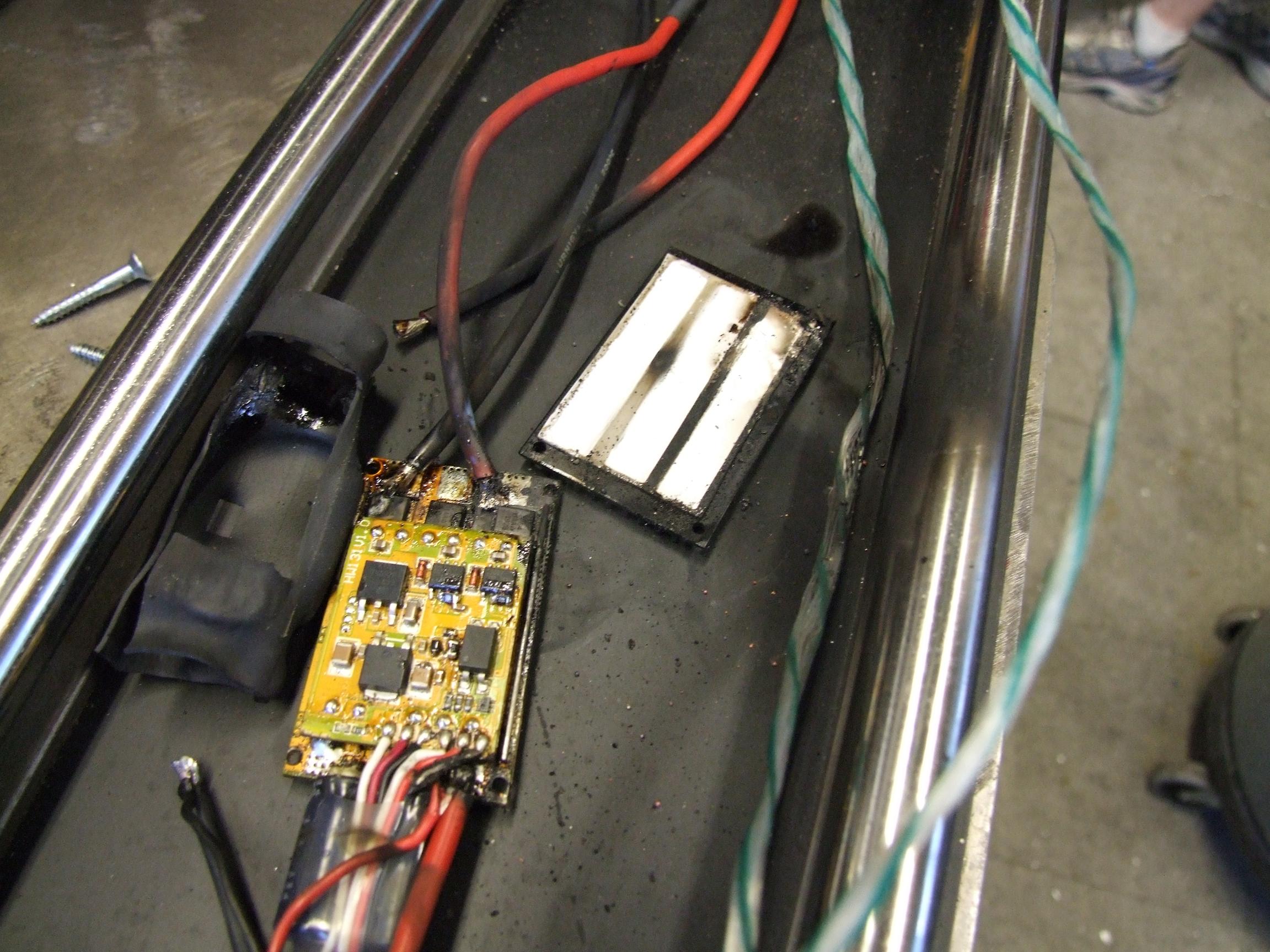
Well, I couldn’t really care less about the CIMs at the moment, but I wanted to make sure my precious custom controllers don’t smoke themselves. Solution 1 was just dropping a slightly trimmed server heatsink under the FETs. This turned out to be not too effective, since the D2PAK FETs don’t have that good of a thermal resistivity from the plastic face. Additionally, the board was still edge-fastened, causing the whole thing to bow a little bit and really not letting the FETs have any heatsink contact. More time drilling holes (to use the center mounting holes) would have alleviated this problem, but…

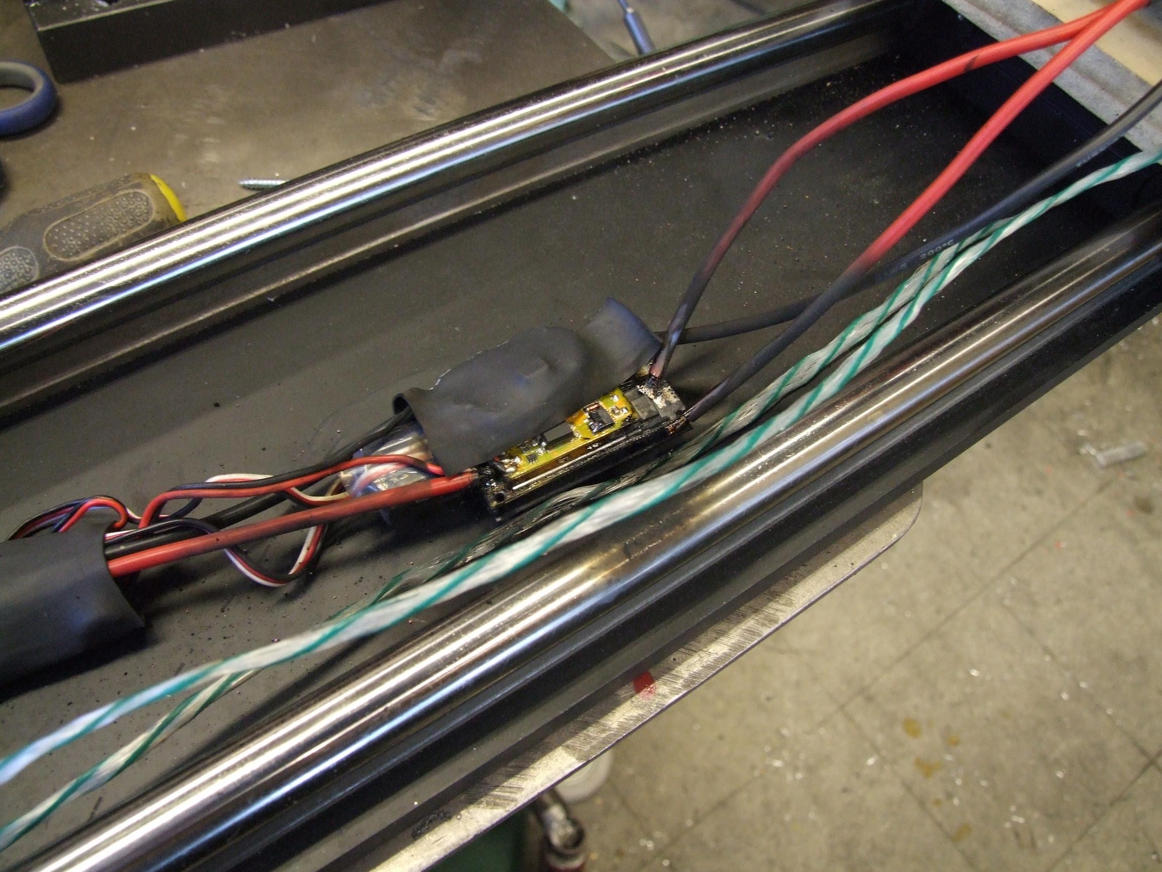
Forced air works just as well in this case. I took out the heat sink and hot glued on a pair of small 1U rackmount server fans, and all was good. The fans run off the 15 volt supply, and the stiff breeze over the board and components that stick out relieved the heating issue – it is at least some finite amount of airflow such that all components and copper traces contribute some to heat removal.
Before this was added, I think the capacitors were acting as a heatsink for the FETs. Hey, copper leads, aluminum plates…

I realized I never actually posted a picture of the rider switches, so here is one. A submini snap-action switch and a 3d printed mount that clips over one of the mounting bolts for the pivot joint. When a rider is present, the slotted pivot presses on the switch. Only one switch has to be engaged for the vehicle to be activated, and when no switches are engaged, the vehicle shuts off the main contactor after 2 seconds.

One little afterthought which can be seen in the video is this wheelie tail. I designed this in about 10 minutes early one morning and cut it out an hour afterwards, so there was really no thought put into it…such as the fact that it’s made of mystery scrap plastic (behaves like Delrin, so I assume it’s something similar) and has huge stress risers at the pivot point.
It also revealed a discrepancy between the CAD model’s tread thickness and the real life one. The tail was supposed to ride about 2 inches off the ground, but in reality this was less than 1 inch, which prevented me from adding wheelie rollers of any reasonable size. In the test video, they are simply shown dragging on the ground. Hey, Delrin is a low friction plastic… stop judging me.
I will probably remake these, as there’s plenty of scrap left to be further up and slightly less out, and mount roller skate wheels on them. Or the wheels from the skateboard that was parted out to build it.

Recharging, after an entire night and morning of drive testing. I’m slowly getting the hang of this thing. All the drive testing in the video took out about 8 amp hours out of the 24 or so onboard – I’m not sure what distance this translates into yet.
next steps
So I’ve built a robot. Hey, I think I’ve done that before!
When testing LBS, my fears of the wheelbase being too short to stay on top of were realized. If you accelerate or brake too hard, the entire vehicle just lurches forward or backward. This is grounds to give the vehicle a little bit of “Segway action”. While it will not balance you outright, the springs in the suspension allow the vehicle to tilt forward and backward enough to sense an angle. While I previously said that the board wouldn’t be involved in the control, I didn’t think about the implications of having a slightly tiltable suspension. I was more thinking of pure weight-shifting scheme which would cause issues with accelerating reference frames. I think the vehicle can at least be programmed to stay under you. That is, upon acceleration, it will recognize a tilt occuring in the opposite direction and slow or stop the acceleration to compensate. I’m probably also going to experiment with forward and backward lean control for the throttle if the acceleration adjustment does work out – after all, if it’s trying to stay under you, there’s no reason that leaning can’t be the only control input.