This post is also known as Why I Should Man Up and Build More Motor Controllers.
RazEr rEVolution is currently assembled as a rolling frame. This means I’ve successfully managed to build a kick scooter again! REJOICE!
Small detail: the DNIR is installed, but the whole thing still rolls and coasts almost like a stock scooter. This is pretty paramount, IMO, because one of the advantage of hub motors like this which I’ve been telling people is that it still allows you to use the vehicle “normally”. Specialized electric drives (like Melonscooter, in fact) are just difficult to blend into vehicles which are designed to be human powered.
But enough harping on why hub motors are cool. The reason I wanted to throw rEVolution together mechanically is just so I can take it out of MITERS for a little while while I seek a motor control solution….yet again. Overall, I’m still in need of a medium to high power BLDC motor controller that isn’t the size of a house brick and has sensored inputs. Kelly controllers (and associated generic Chinese motor controls of the same genus) are the size of house bricks, and R/C airplane controllers, while cheap and available with high amp capacity, are sensorless and therefore have extremely poor startup characteristics for hub motors. The Turnigy ESC has been performing great on Melonscooter, but only because it has a 4:1 belt drive helping the motor.

In this picture: (1/4)² inertia divider.
But what about the DECs? The thing that I had the biggest e-b0ner in the world for? Well, they were (and are still) performing admirably driving the Skatemotors. They’re well matched to each skatemotor, power-wise. But the DECs are still industrial motor controls, and with that come some issues. Specifically, they really do control speed. We call these things “speed controllers”, but at least airplane motors and most small EV controllers (including the Kellys, which can be configured in a few ways) are open loop. They’re knob controlled – you turn the knob, the motor goes. You turn the knob more, the motor goes some more, but there’s no guarantee.
The reverse is what causes trouble with rEVolution. The DECs appear to use synchronous rectifiers, which means the motor will brake if the command results in a motor speed lower than the current one. While this is used on LOLrioKart’s controller too, the DECs actually attempt to hold 0 speed unless specifically disabled.
Unfortunately, that last part kind of ruins the ability for the scooter to be kick scooted. Now, they do show this same behavior in the skatemotors, but those motors are substantially smaller in diameter and length – so your inertia overcomes their deceleration much more – and I’ve specifically programmed the Arduino running the two FSR throttle and brake inputs to throw the shutdown line on the DECs if each successive throttle reading is less than the previous one i.e. you’ve let go. So the skates can coast, no problem.
So then why not just use the same arrangement for rEVolution? Well, if I’m going to have to hook up a microcontroller and write software for it, I think I can do the whole system better and possibly learn something while I’m at it.
Shocker.
Anyway, that’s why rEVolution is currently a very elaborate kick scooter. Give me some time…
Here’s some pics of the mechanicals in the mean time!

Assembling the finishing details was fairly easy. The Garolite top plate goes on top of the aluminum frame, and then the steering neck / folding joint sandwiches it. Originally, the four holes were tapped for M6 x 1 screws so I could use the Razor scooter’s stock mounting screws. However, I’ve managed to lose them, and not having M6 screws at my disposal, I dynamically rethreaded the holes for 1/4″-20.
The two cutouts in the top plate are to go around the joint reinforcement screws. I’m proud to say that after a few bunny hop tests, they are holding up well.

Here’s the finished profile of the scooter, showing the interesting side. A Deans-shaped cutout holds a battery connector for charging and the main power switch.

In folded mode. I’ll be honest: This thing is heavy. It’s probably bordering on 20 pounds just because there’s so much \m/etal in everything.

Beauty shot!
Right now, I think the design looks a little “off”. The wheel widths are so disparate and the rear wheel such a commanding color that it just sort of dominates the entire design, and the front looks weak and atrophied by comparison. It’s like a queen ant – small head, huge abdomen. Like Shane did with Pneu Scooter’s new front forks, I might re-engineer the two-piece Razor A3 fork such that it holds a more manly wheel – maybe another one of the McMonster Truck Tires that I hollowed out for the back!

Compared side-by-side with Melon-scooter (which, incidentally, now has head and “tail” lights since I do operate it alot in open traffic…because it’s fast enough to keep up with most area traffic).
It’s not really that much smaller. Still a size class or two down, and currently, much less mobile.
melontroller
I’ve talked about it before, many times, the most recent time after I ended up reverting to the Turnigy sensorless controller. One of these days, I was going to build a BLDC controller that actually works, and is a little smarter than the average airplane monkey. Since I pledged that if I had to ever write code to drive a motor controller it might as well be a system of my own design, I’m going to take myself up on it right now.
One day (okay, midnight-early morning) I sat down and began scratching out a schematic in Eagle. What did I want in this controller?
- 50 to 60 amps continuous. Real continuous amps. With FETs that can handle this, I’d say a hundred amps peak pulsed is probably doable.
- Operating voltage in the 36 to 48v range, since I’m unlikely to go higher than the number of cells I have a battery charger for.
- Single motor, sensored commutation.
- Current sensing. It’s taken a long time, but I’m finally convinced that current control of an electric motor is b better than speed control. I’m still a die-hard open loop guy, but if I had to implement some kind of actual control loop, it’s going to be the one with a real world physical state variable (torque, current, acceleration, and inertia are all linked pretty much directly)
- Arduino-compatible. Because…. because.
After a couple of hours of blitzing, here’s the result.

Eagle, what the hell did you do to my schematic?
I literally opened the schematic again after seeing how it wanted to place the components to-be-routed on the board and my gate drives started sucking in the passives around them. That image capture is from after alot of rearrangement.
But the gist of it is:
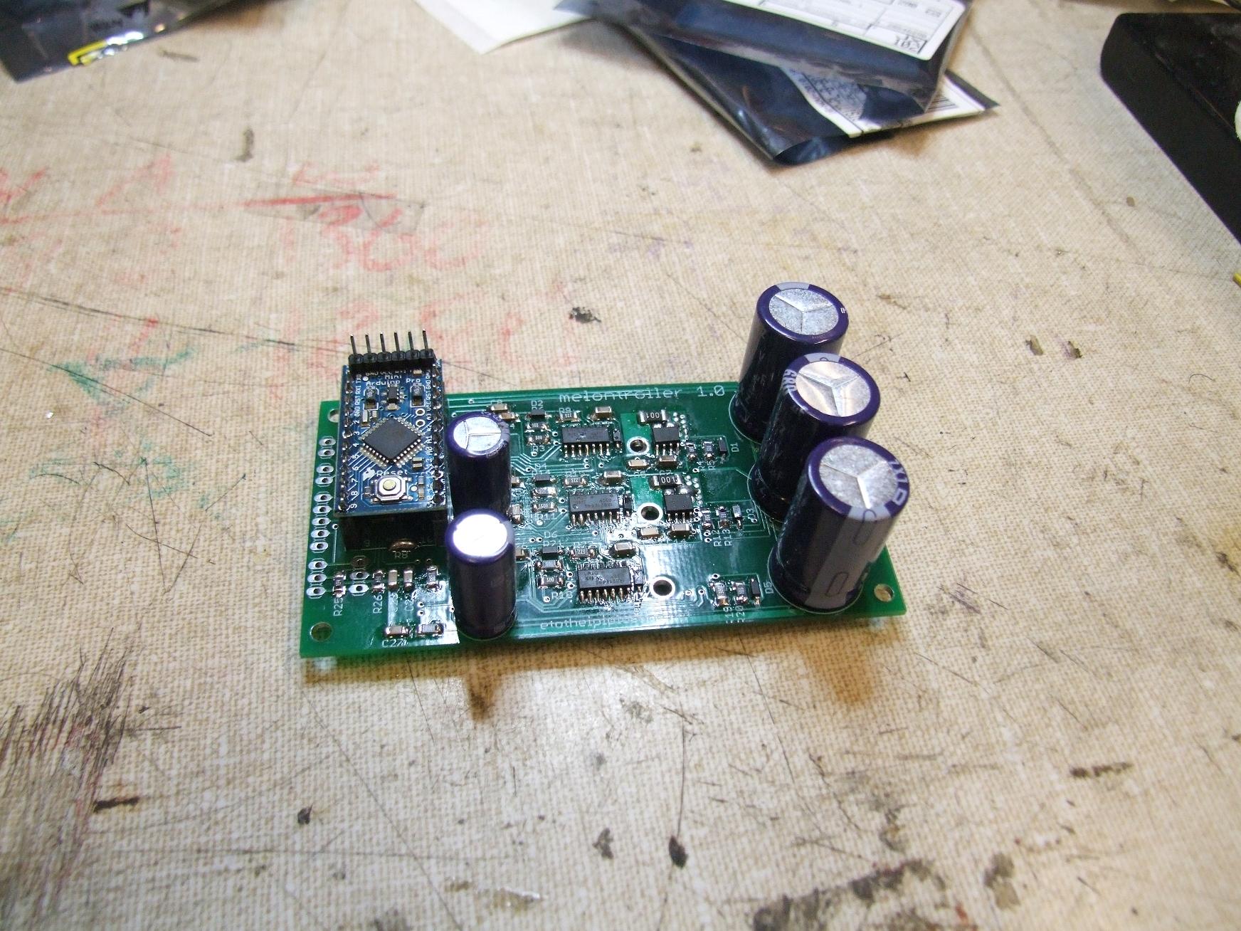
- An Arduino Pro-mini
- IRS21844SLBBQLOLWTF half-bridge synchrec drives
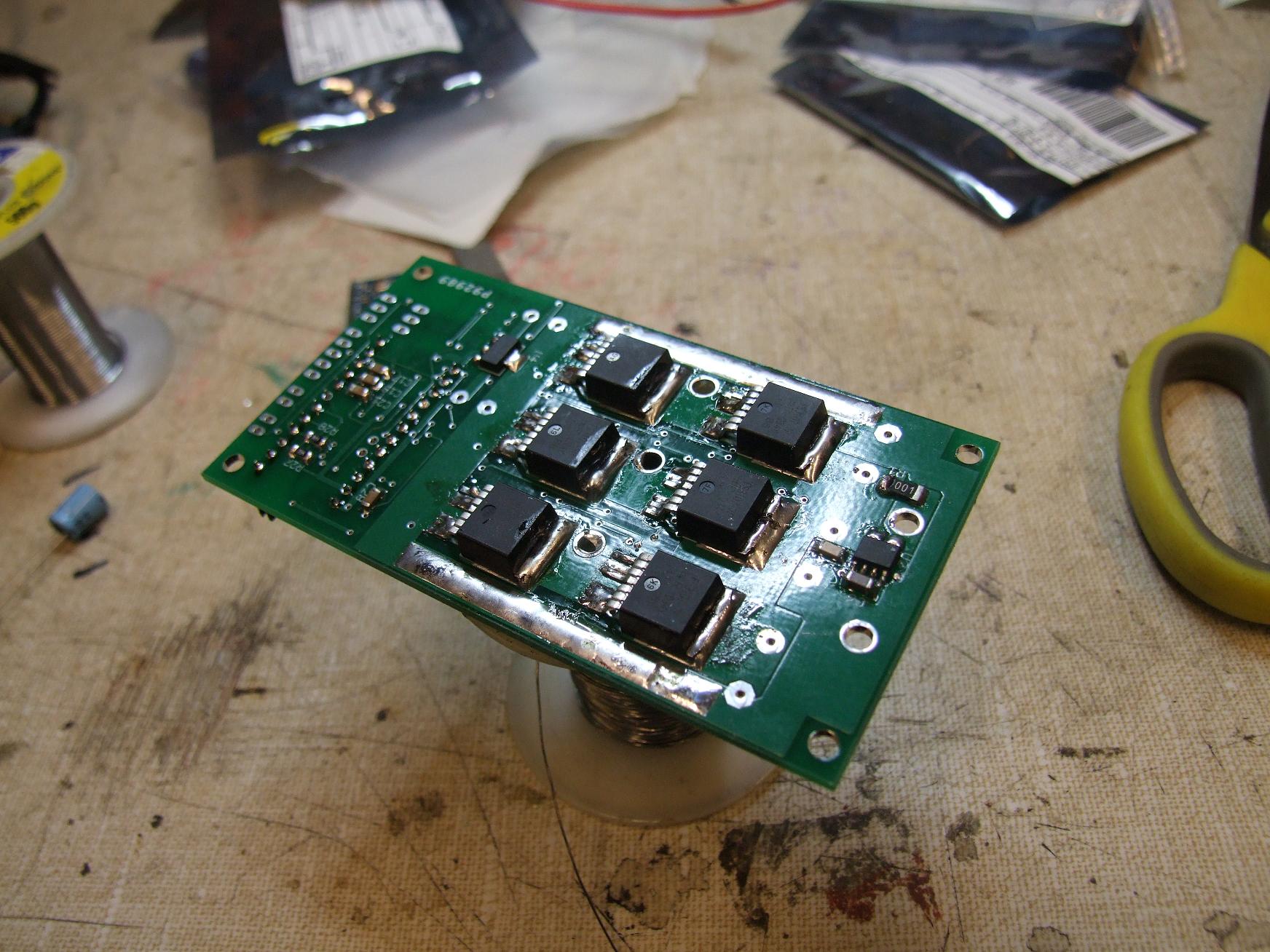
- IRFS3107 cracked out FETs in the even more cracked out D2Pak-7 package.
- Seriously, if this whole system works out, I’m asking International Rectifier for sponsorship. Not because I need it, but because they’re awesome.
- Three ACS714 Hall-based, bidirectional current sensors. One on the DC rail, and two on the actual motor phases. Result? Ability to measure both DC and AC side current in both directions. Life could get interesting in the future.
- Two analog and two digital inputs, because I can’t quite decide what I want to do with them yet. So they’re generically named.
And after about 9 hours of advanced ninja board routing, here’s the end result:

Advanced Ninja Board Layout, MIT Course number 6.9000
I’ve sent out the BOM to Digikey and the board itself (just one for now) to Advanced Circuits (who I absolutely adore now because they tooooootally saved our bacon and even gave us a massive discount on the boards for our 2.009 project which we needed EXTRA EXTRA SOON and are therefore the most awesome PCB fab house anywhere, so much so that I’m making this whole block of text one huge link to them).
With some luck, and some code wringing, there ought to be some Melontroller in my future.
The D2PAK fets don’t have that much PCB copper to sink heat to, so my continuous amps goal might be a bit optimistic. But that’s one thing I want to test. I don’t care – honestly, I would much prefer to melt components right off the board because I purposefully commanded them to flow such a high current continously and the know that the design itself is sound, rather than have everything just detonate when I plug it in. The former is a glorious death, the latter a shameful one.
mini-melontroller
Now, the controller above is too massive to fit in RazEr. I’m already mulling over making a much more compact board, possibly with the Arduino on surface mount headers so it can park over the 3 phase bridge. The bridge would also be smaller both physically and ampacity-wise. Mini-melontroller should fit on a standard credit card.