So typically, a Boxcar update involves Motorama, my perennial winter robot festivity back north of the Mason Dixon line. However, in 2025, conflicting work travel turnaround times made it basically infeasible to commit to going. Therefore, while a lot of the design and some of the building of Boxcar happened over winter (and some really dating back before Dragon Con 2024), I really just targeted getting it together for last year’s Robot Battles.
We begin the story some time in late summer 2024 (Man, I’m keeping this website so up to date lately). Remember that Boxcar ended up a parallelogram last Motorama when I ran into Big Cookie one too many times. So, that frame went into the machine shop recycling bin, which meant I had to bash together a new one.
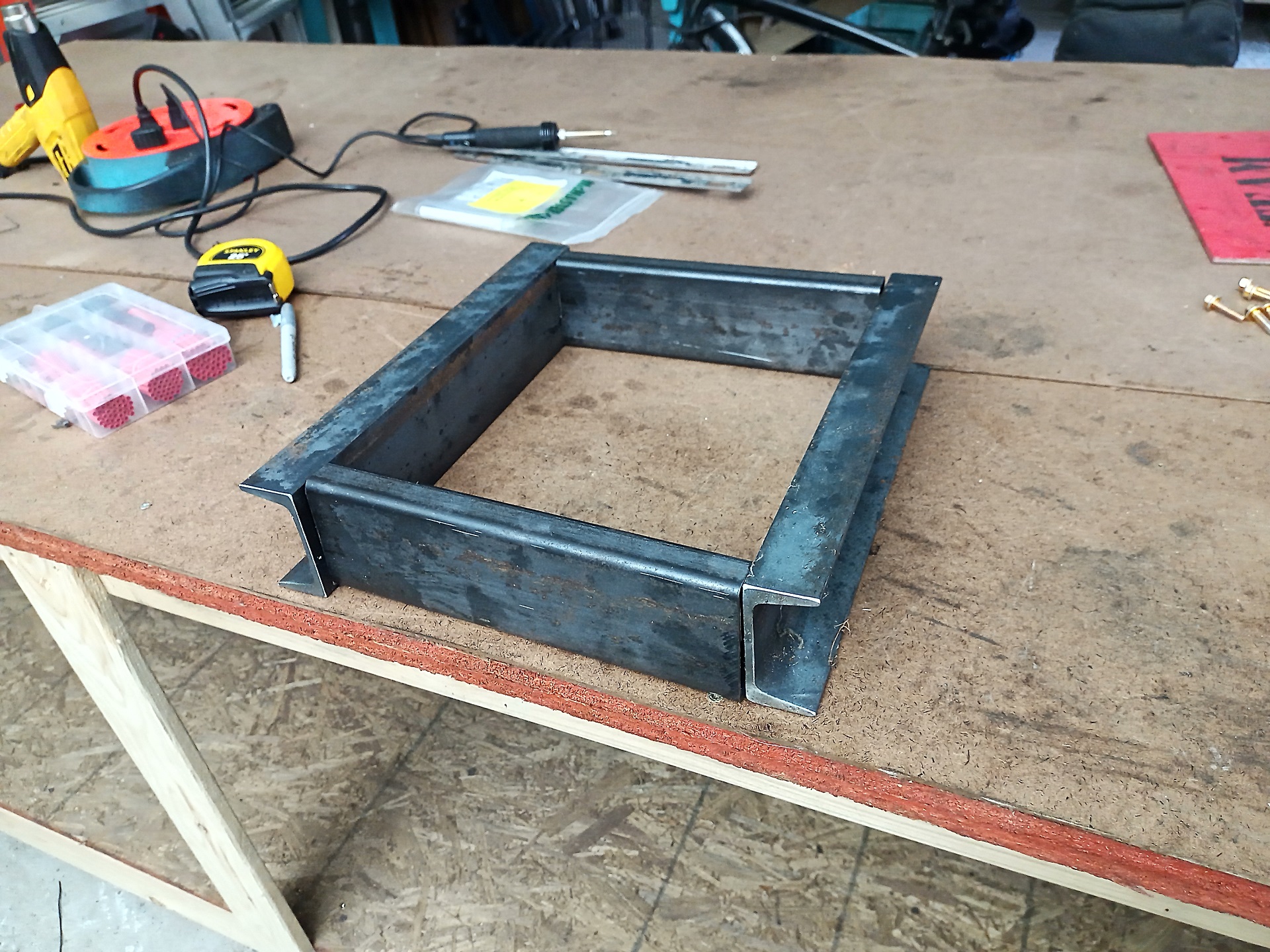
Luckily for me, Boxcar was assembled solely using the drops shelf at the local Metal Kroger. I had no plans to change the dimensions or do anything different, just pop out a spare. I just cut another few feet off the nearly full sized channel and tube I bought in like 2021 or something.
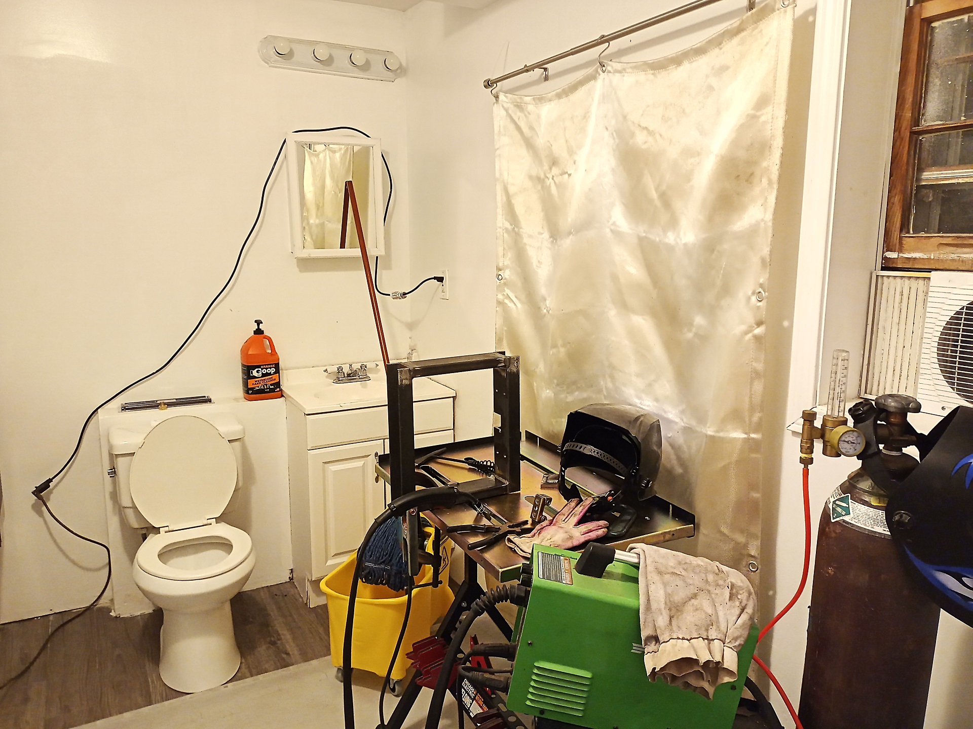
After the pieces were cut and the joints and cutouts machined, it was off to the …. uhh, bathroom to weld the corners together. Yes, this is why men take forever in the bathroom – we’re trying to knock out the last few welds.
(For one reason or another, the Internet gets very upset at the concept of the Welding Bathroom. I noticed a lot of people think this is my ONLY bathroom – which to be fair, would be very stereotypical terminally unmarried behavior)
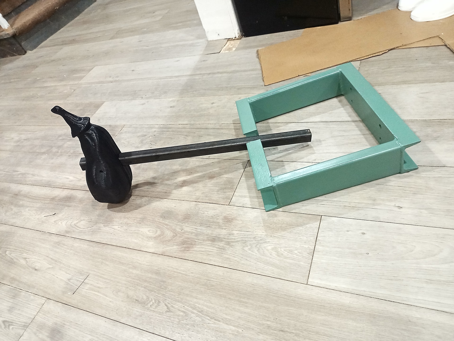
After a new coat of “Detroit Diesel Green”, the color given to me at the start of this whole mess when I asked for the ugliest color paint the O’Reilly’s had on the shelf, I was in business. This brand new and shiny frame (and associated 3D printed eggplant) was just unceremoniously dropped on the still-working bot for Dragon Con in 2024, and it did alright – mostly making a big mess in the rumbles eggplanting all over everything.
At the end, I was down two drive motors and pretty much was just hobbling it around, which became part of the motivation for finally making it a “real” bot.
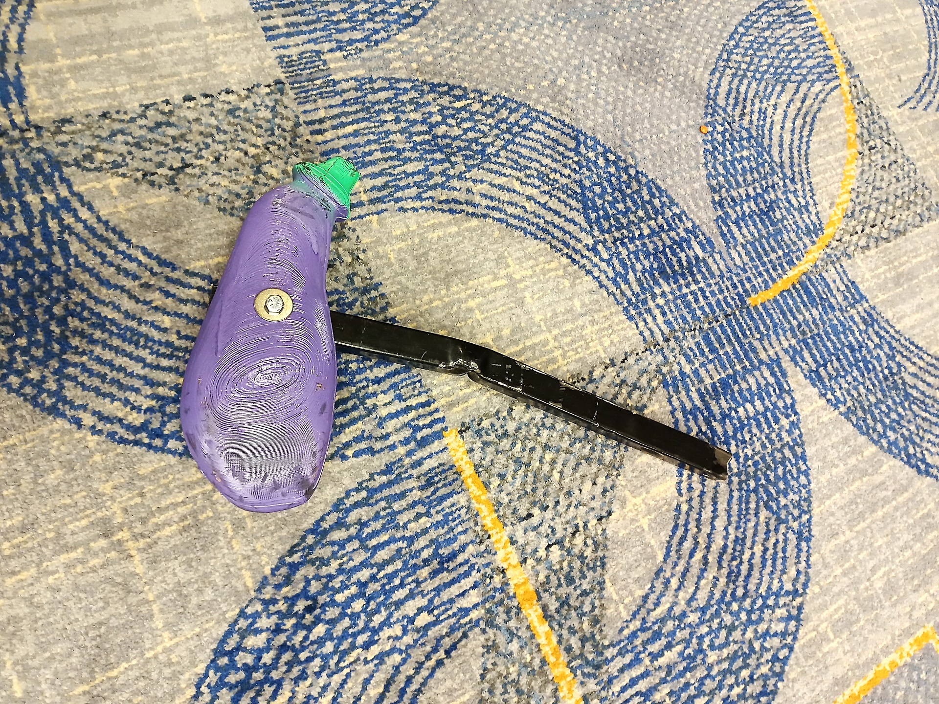
In fact, after it managed to somehow buckle the steel tube (granted, it was only 1/16″ wall), I found that the… uhh curvature of the member improved the impact posture. A lot of hammerbots do have some…. curvature in the member for a better impact angle against an opponent, within a range of heights. Maybe I’ll just keep this design as intentional in the future.
And so, Boxcar sat on the robot cruft room shelf after Dragon Con 2024 while I simmered over the redesign. Some of this build happened over the winter months, the rest (mostly related to the chassis) got bundled up closer to the con, but for presentation I’ll organize the steps in a reasonable narrative order.
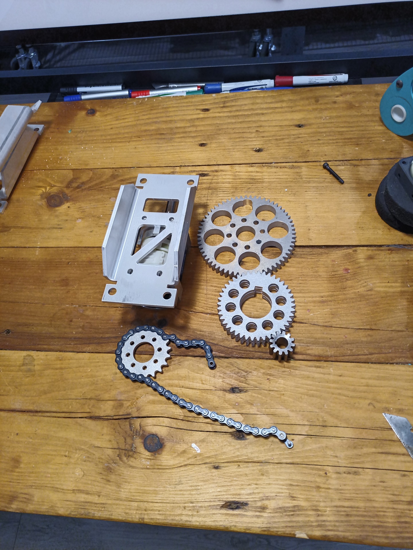
It’s always a pleasant day when you get SendCutSend Christmas and it’s not Actual Christmas. I’ve been spoiled by SCS for work purposes now for a long time, but haven’t yet made much for myself!
SCS and friends basically changed the landscape of engineering design work by putting a fast food menu of high-precision sheet metal ops right in front of you. There’s basically no more excuses. For work, I’ve made gaggles of sheet metal enclosures and bracketree that mated up and aligned with almost billet machined part levels of prevision.
This is in stark contrast with my years of experience with sheet metal layout and farmout long ago. Even worse is if I have to run the brake press myself, because I guarantee that no two bend lines will be parallel, no radius and flange height consistent, and no two angles congruent. I was “afraid of” sheet metal and hybrid sheet metal designs for the longest time because of this. That changed with this build, when I finally had to set up my Sheet Metal workflow and design rules at home.
Alongside the main DeWut mounting crossmember, I had the sprockets and gears popped out of 3/16″ aluminum. Laser cutting precision has also come a long way too – those 12 pitch gears mated perfectly out of the box with one of 30Hauls’ old waterjet-cut 1/2″ aluminum gears.
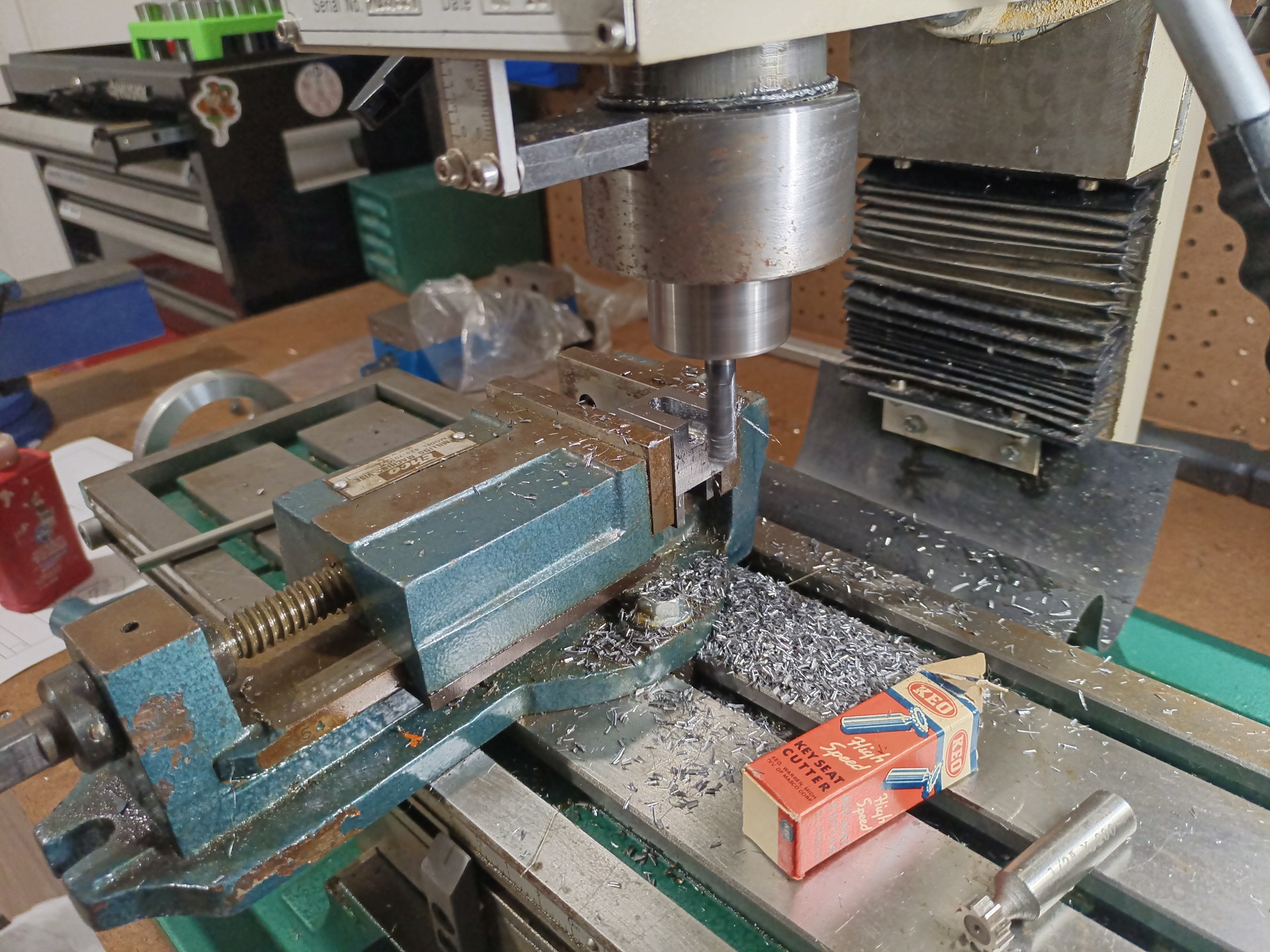
Before I could get assembling, I had to conquer a side quest boss. The “brushless DeWut” conversion of course needed me to pull the pinion geas off the OEM DeWalt 18V motors. This has been a notoriously difficult exercise because of the design of the motor nose plate, which hides the backside of the pinion and largely prevents you from using any kind of off the shelf gear puller.
So I was going to cook up a custom puller, made from a block of steel with just the right dimensions to grab the DeWalt motor pinion.
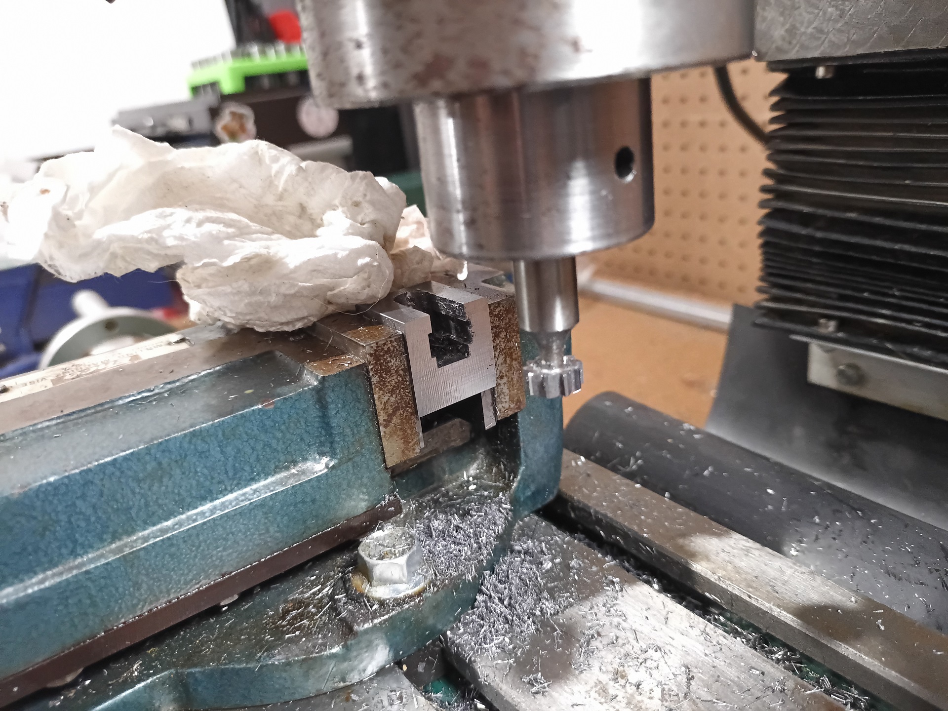
I milled a channel into the 1″ steel cube and opened the bottom up in stages with a T-slot mill.
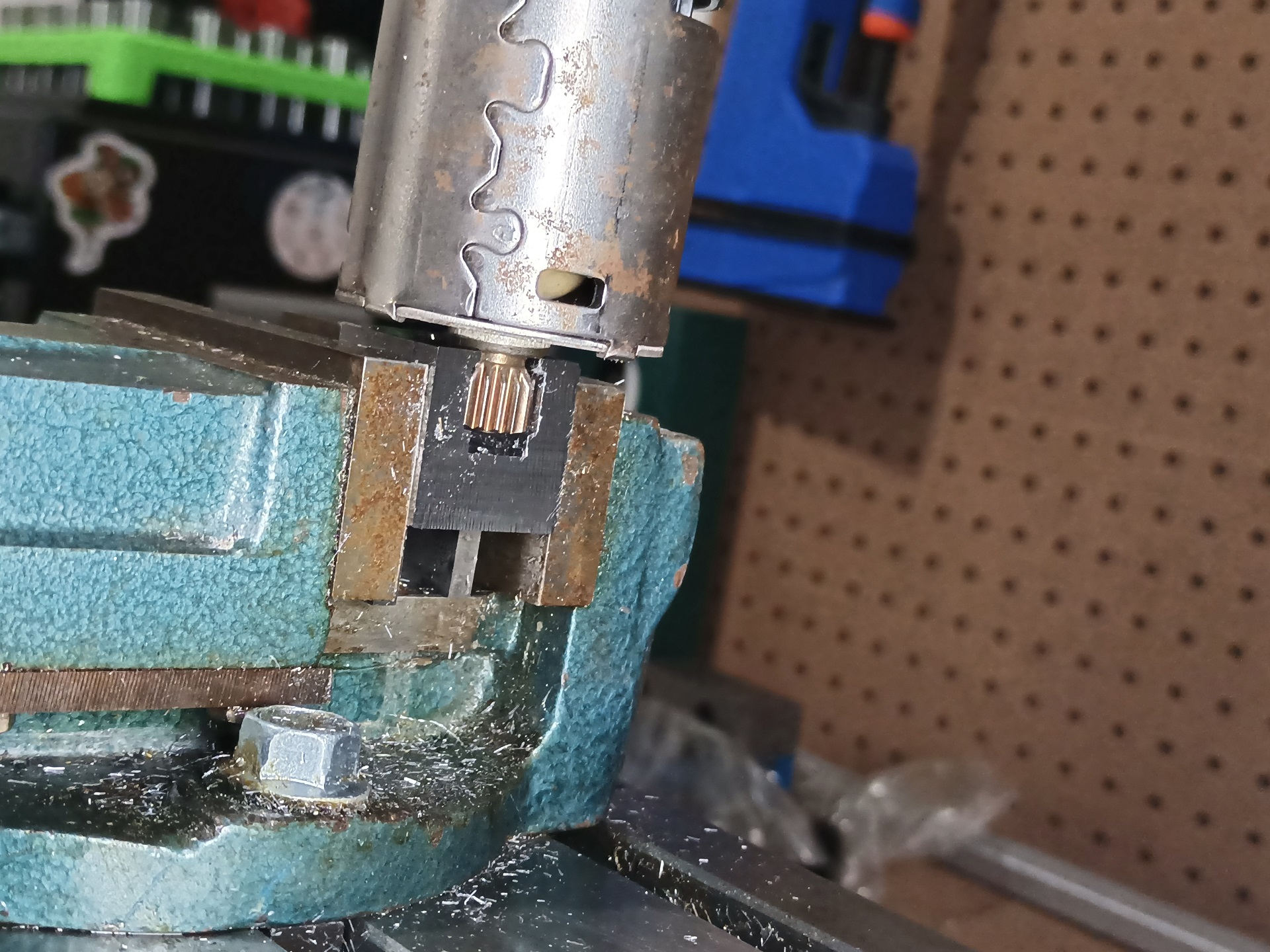
This is the principle here. The top of the T-slot channel grabs the pinion just inside of the teeth, whereas most gear pullers need to wrap around the motor shaft.
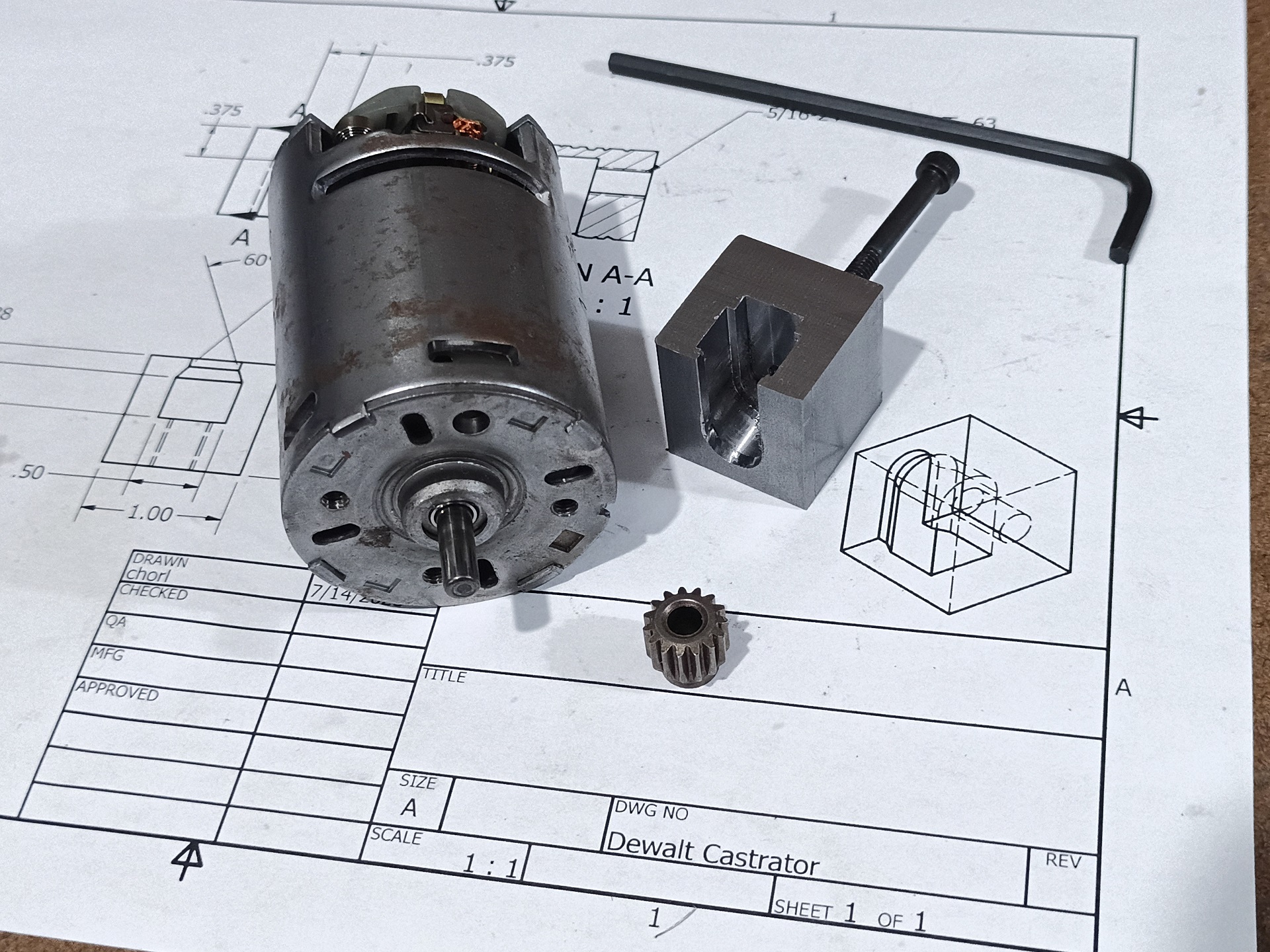
I used a #8 alloy steel socket cap screw as the driver. If that seems a bit undersized, it’s because it IS (for the amount of force people told me it can need), but it was the largest diameter screw that would natively fit inside the 5mm pinion bore. I just compensated some by giving it a 3x diameter thread length, so maybe I’d just twist it off before it blew its own threads off.
It worked extremely well in the end, because… well, it actually didn’t need that much drive screw force. I think because so few people have ever pulled DeWalt pinions, the operation maybe reached some kind of mythical, oral legend status among the builder community. I basically found out that the cyclops was actually an aggressive meat-eating rabbit – still fearsome, but not as big of a deal.
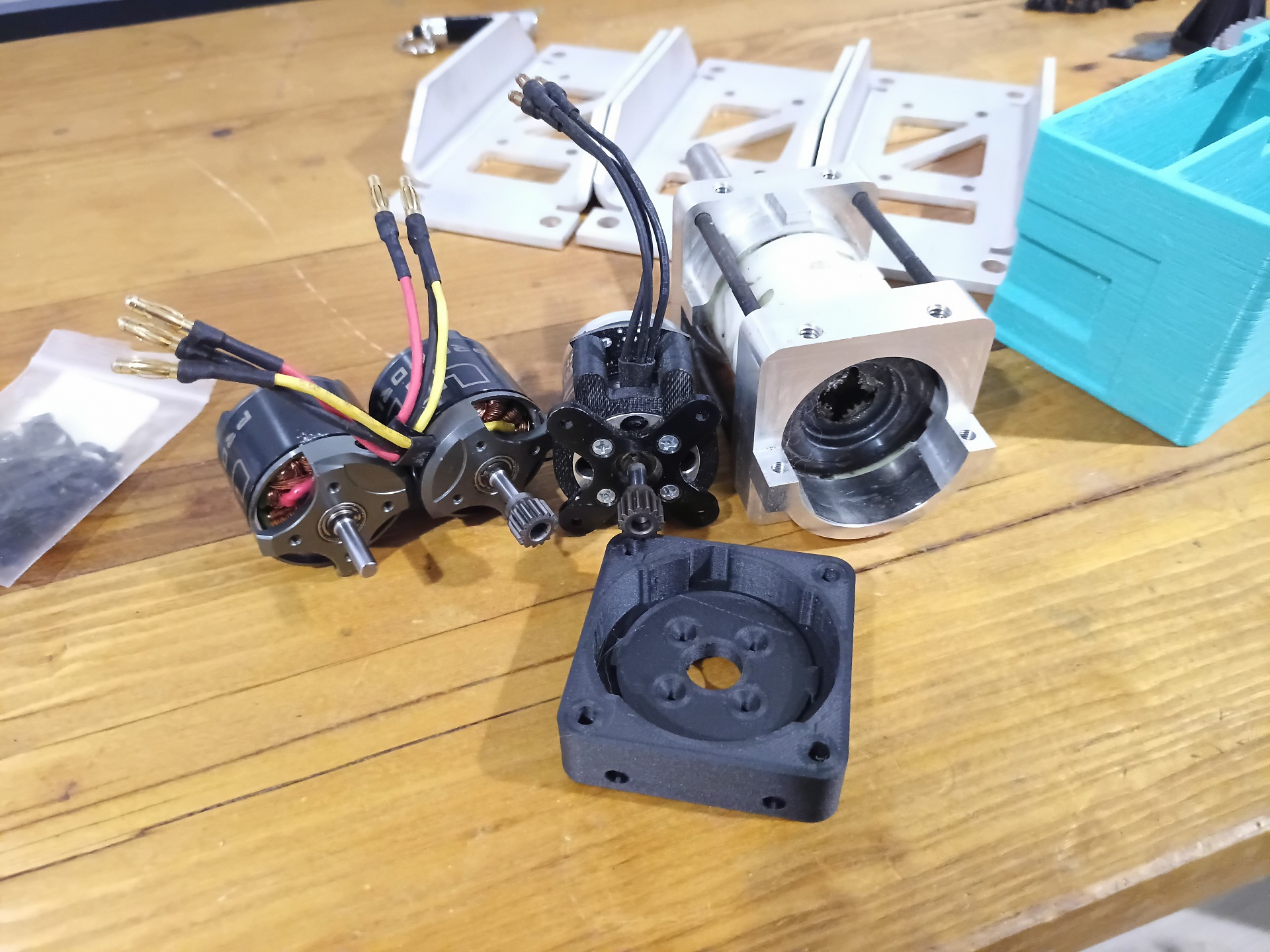
And with that, I salvaged pinions off two of my leftover DeWalt motors and was ready to assemble the 42mm brushless motors on them. They were pressed back on with green Loctite 609 retaining compound.
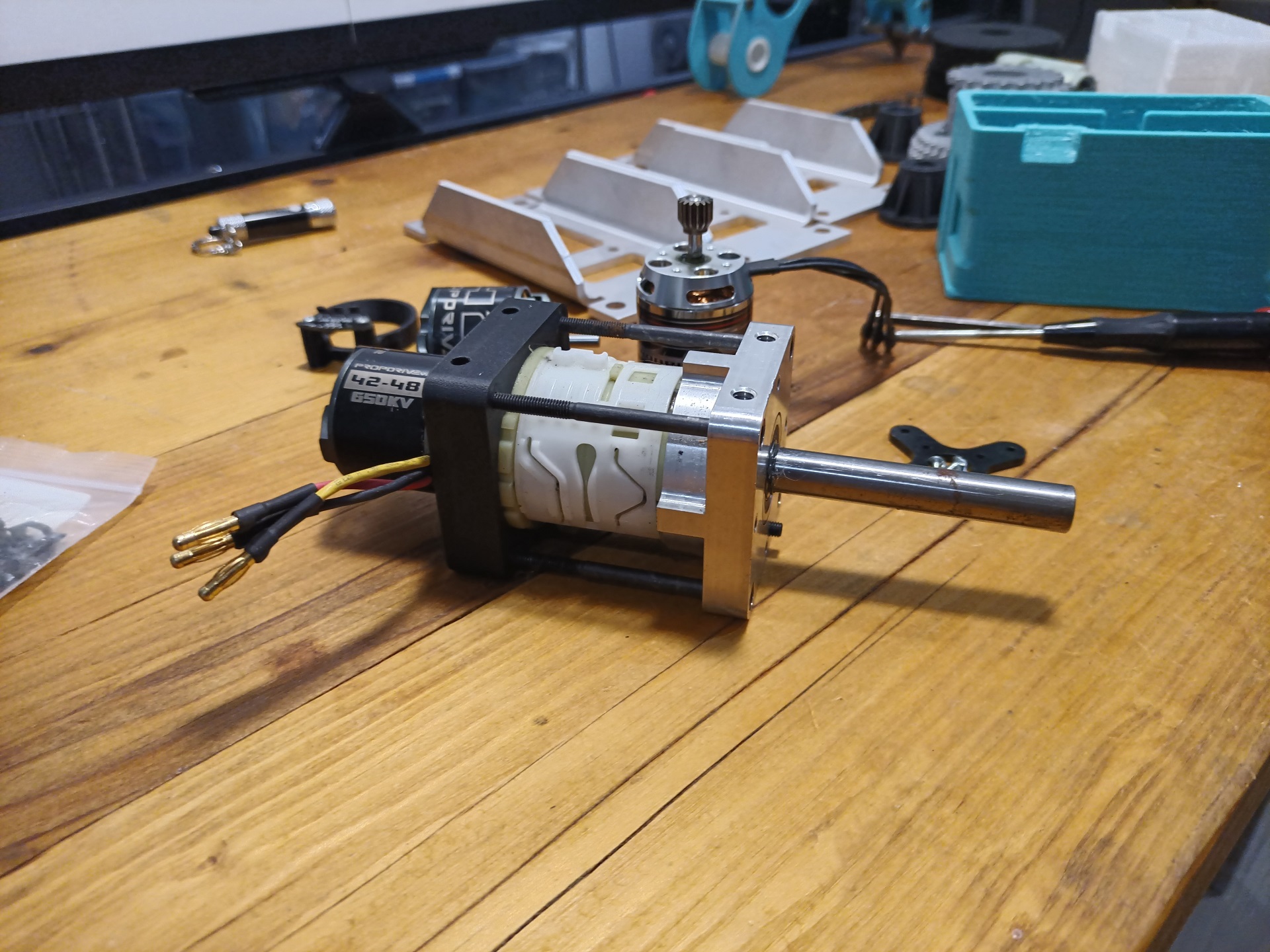
The finished product! Everything went together without issue, since the replacement motor mounting block was designed to be the right depth to use the OEM standard 42mm motor shaft length, without cutting or grinding anything.
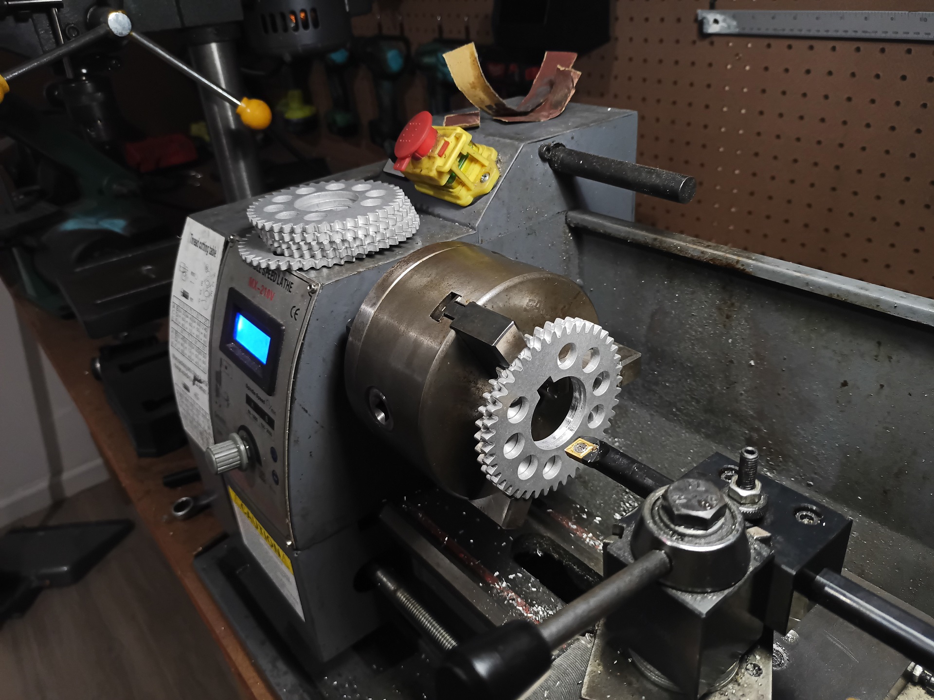
Next up, I worked on crafting the new geared lifter/eggplanter hub. I needed to clean up the laser-cut bores of the main lift gear laminations, which was a quick boring (literally) operation. I just declared Law of Averages here and stuffed a bunch of gear slices in the chuck, figuring it had enough teeth engaging with the chuck to kind of sort things out concentricity-wise. Somewhere, my old Machine Design professor suddenly grabs his temples and screams.
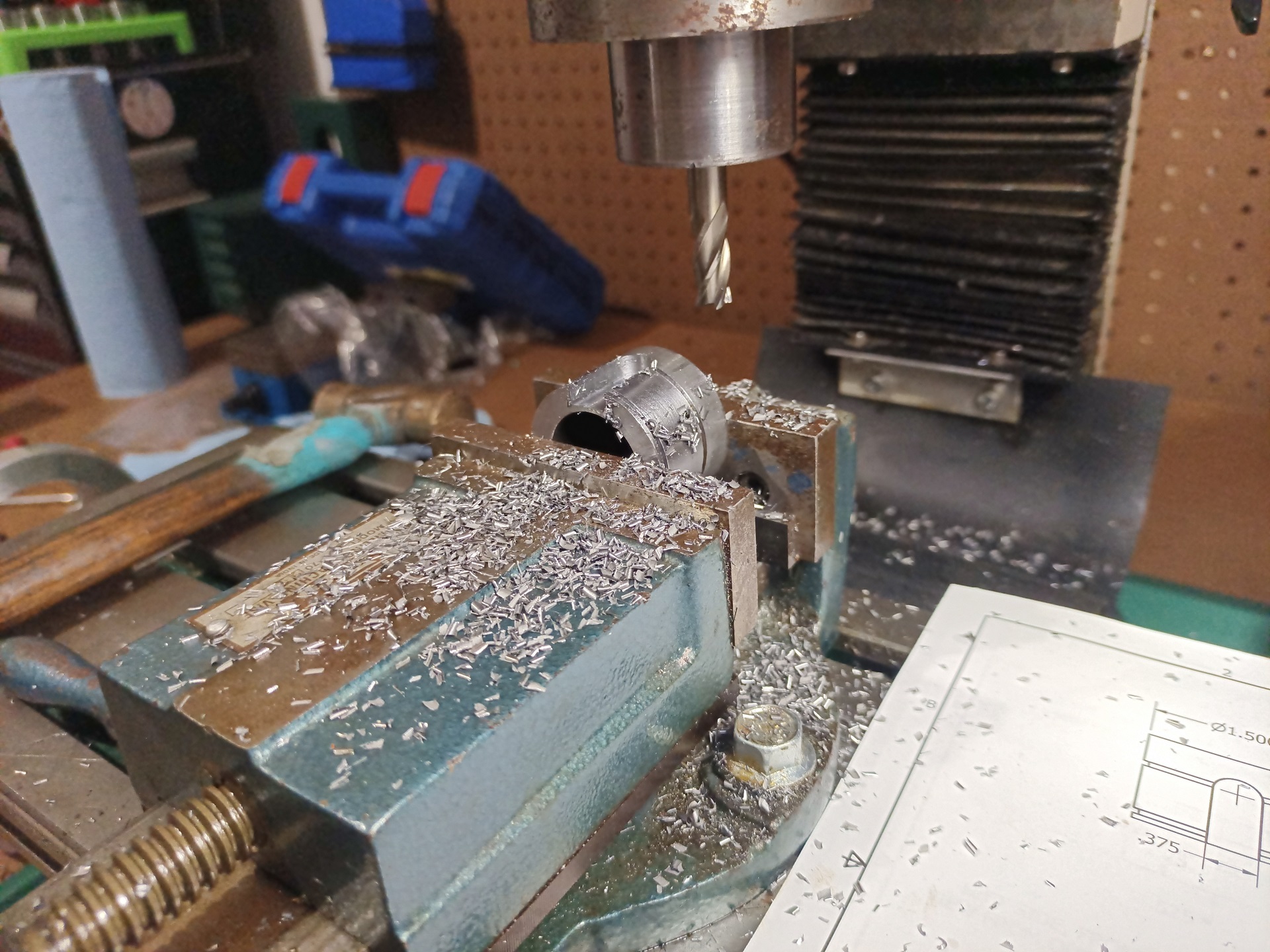
The hub itself is a chunk of thick-walled steel tube stock that I put two big snap ring grooves and a 3/8″ keyway into – it matches the dimensions of a 1.5″ standard keyed shaft. It gets welded to a thick-walled 1.5″ square tube which the smaller 1″ whatever i put on the bot gets bolted into.
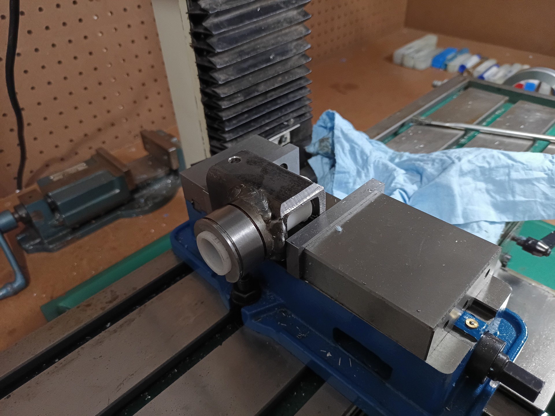
Back from the welding bathroom, I added a large chamfer to give clearance to the DeWut as the assembly rotates.
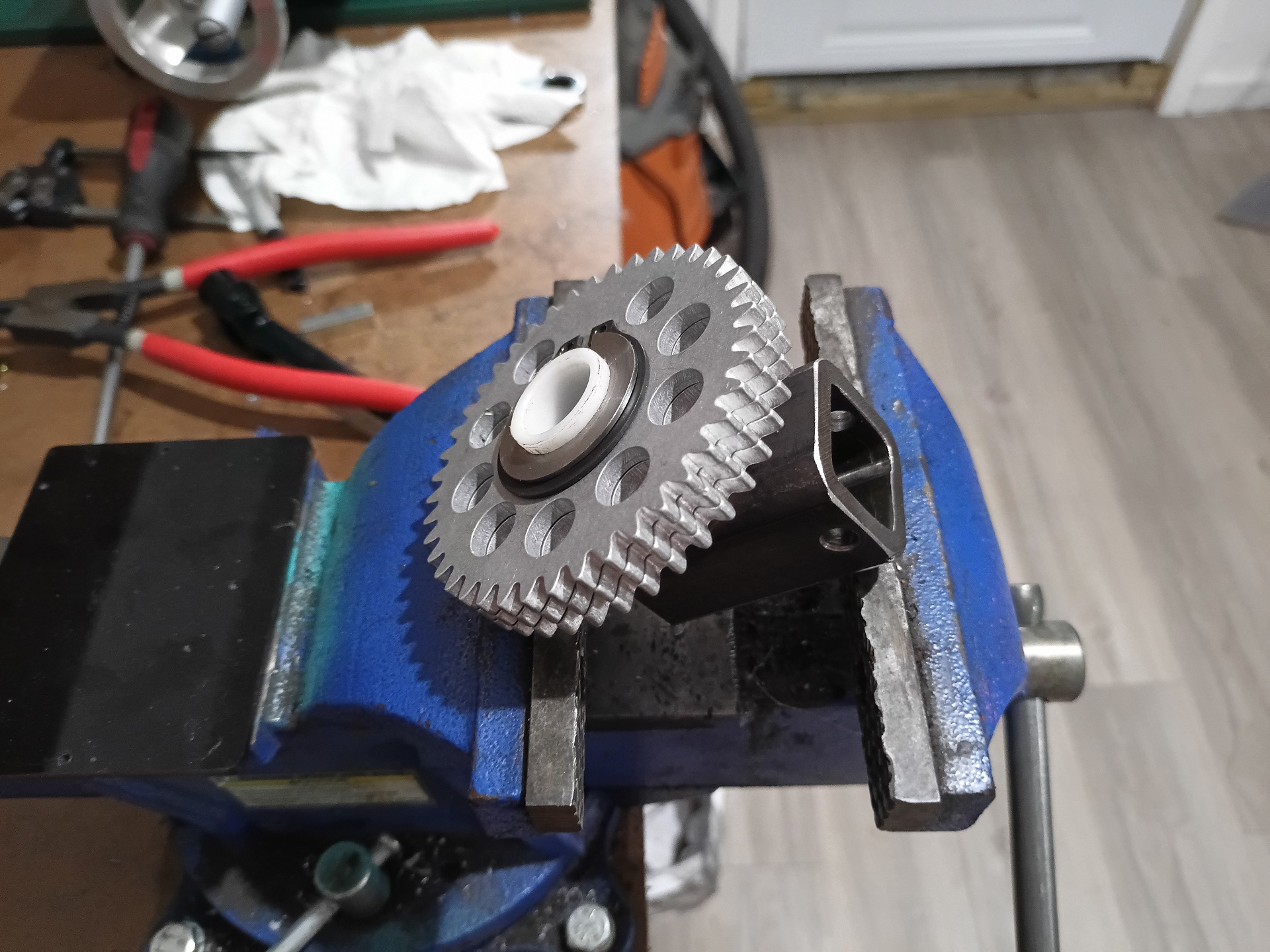
This is the completed hub after welding and processing, with the gear slices stacked on. The slices are retained on both sides by a big 1.5″ snap ring, applied using the most terrifying snap ring pliers I’ve ever had to use, which I picked up for Stance Stance Revolution previously.
That was a double face protection moment – safety glasses under the whole-face shield. Luckily, I only shot it off one time!
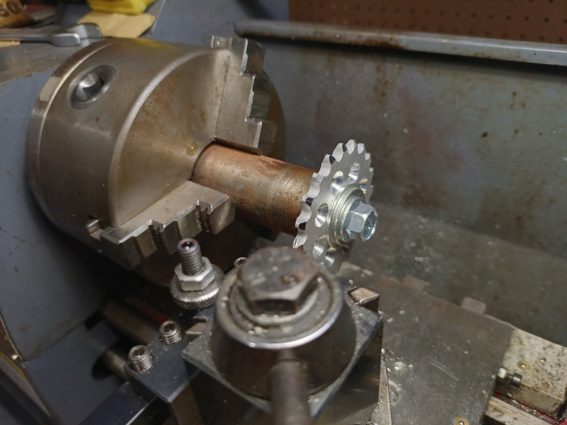
Moving onto drivetrain assembly, all of the drive sprockets got an edge chamfer using a quickly-made mandrel.
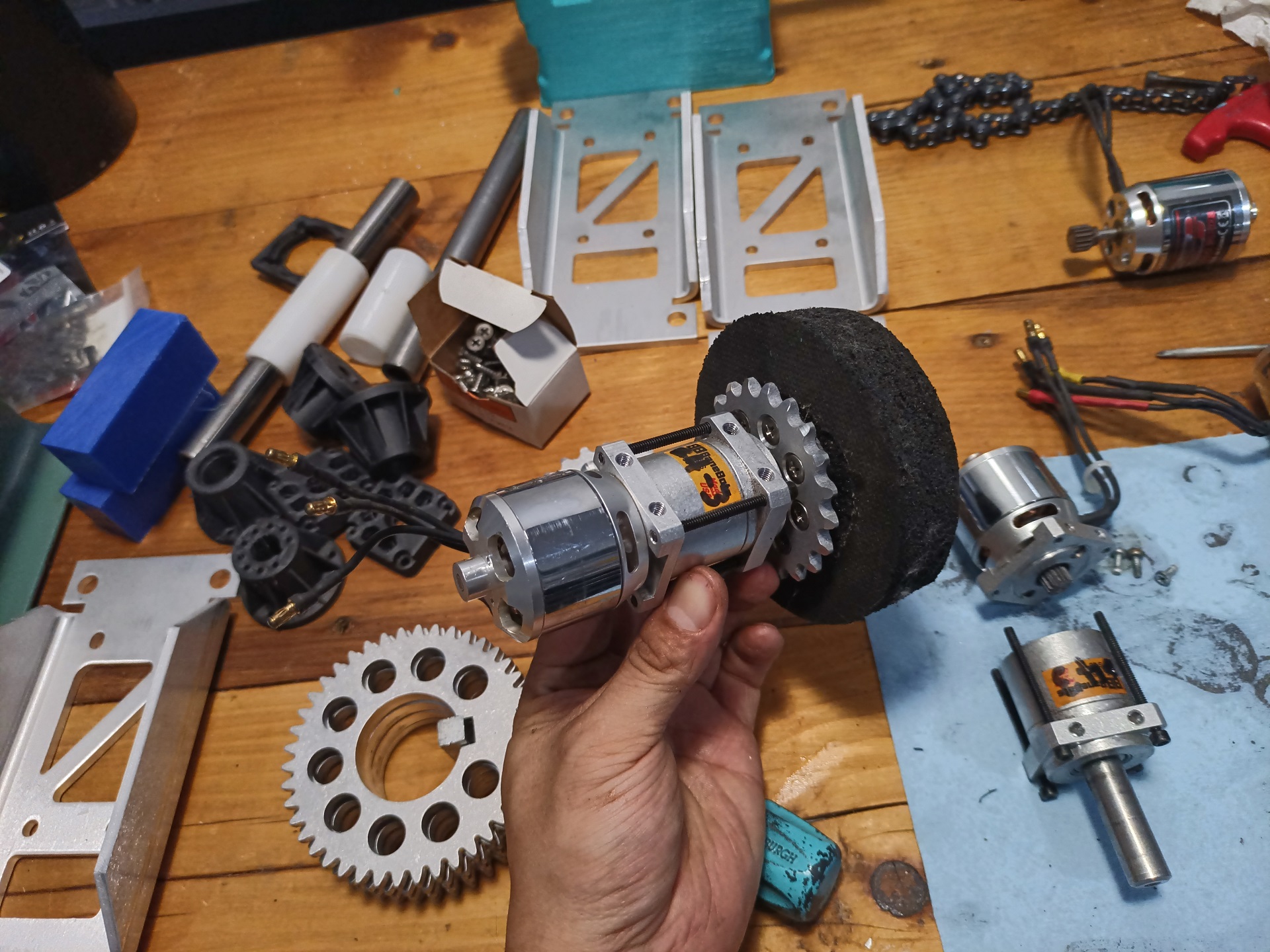
The drive assemblies are pretty straightforward, with the hubs and tires built the same way I’d been making them (though these days I just incorporate the little adhesive-and-torque-promoting blades into the hub itself). Eight plastite type self-threading screws, probably overkill but an easy number to count to, hold the sprockets onto the plastic hubs.
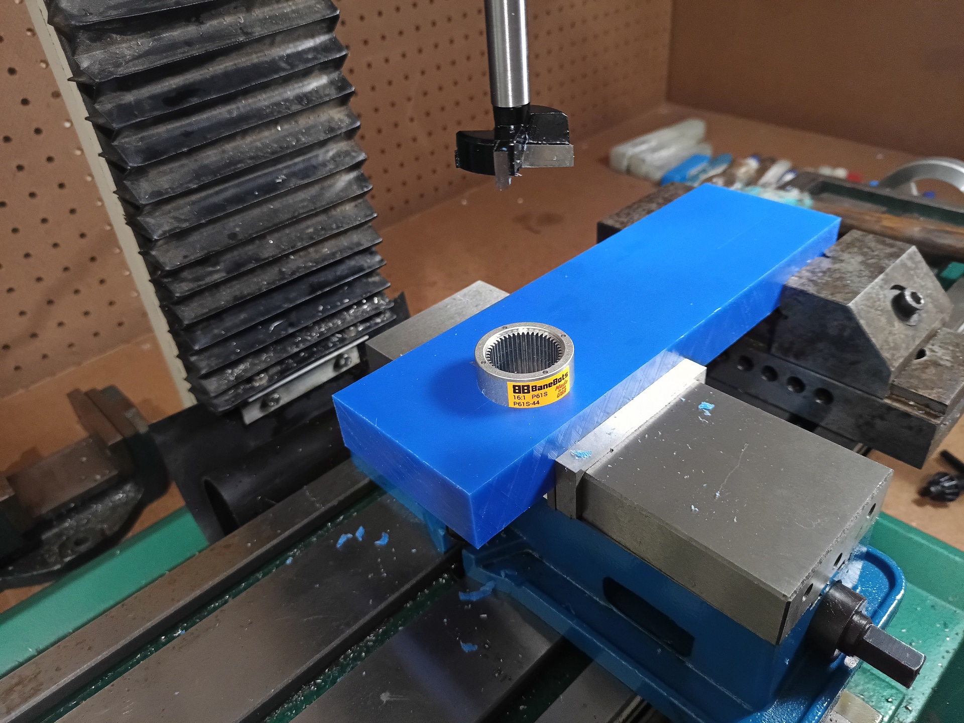
Now we’re getting into the heat of the build with chassis work! I picked up a 38mm Forstner cutter to cleanly make a hole through the UHMW frame rails – a regular hole saw would have been fine too, but the closeness of the tie rods holding the gearbox together made me want closer tolerances than a hole saw would manage. The P81 ring gears are a little under 1.5″ in diameter, making the 38mm hole a light slip fit.
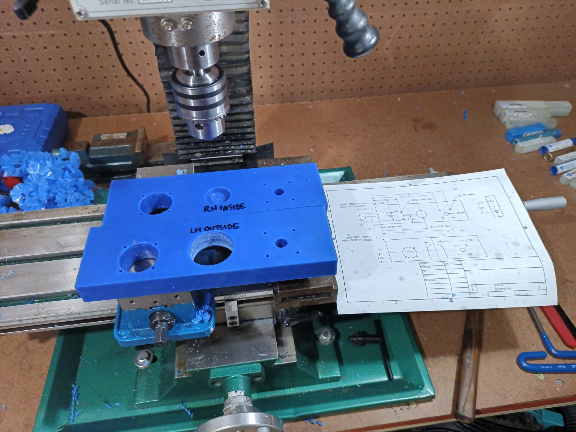
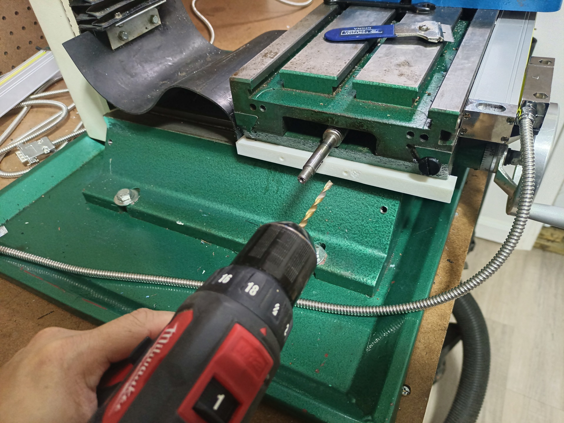
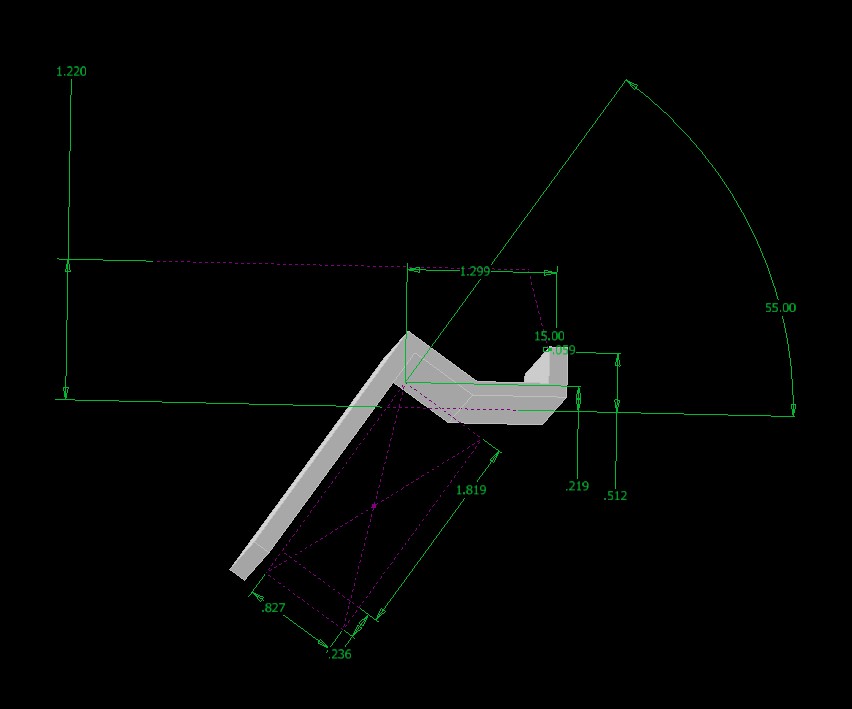
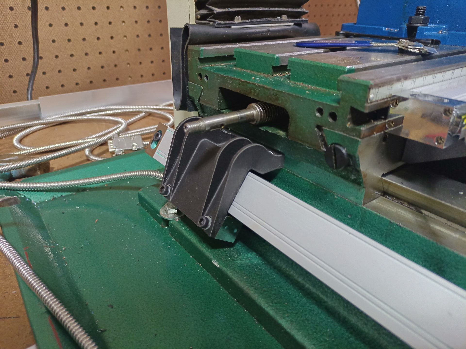
I made drawings and drove the mill myself like some kind of 20th-century scrub.
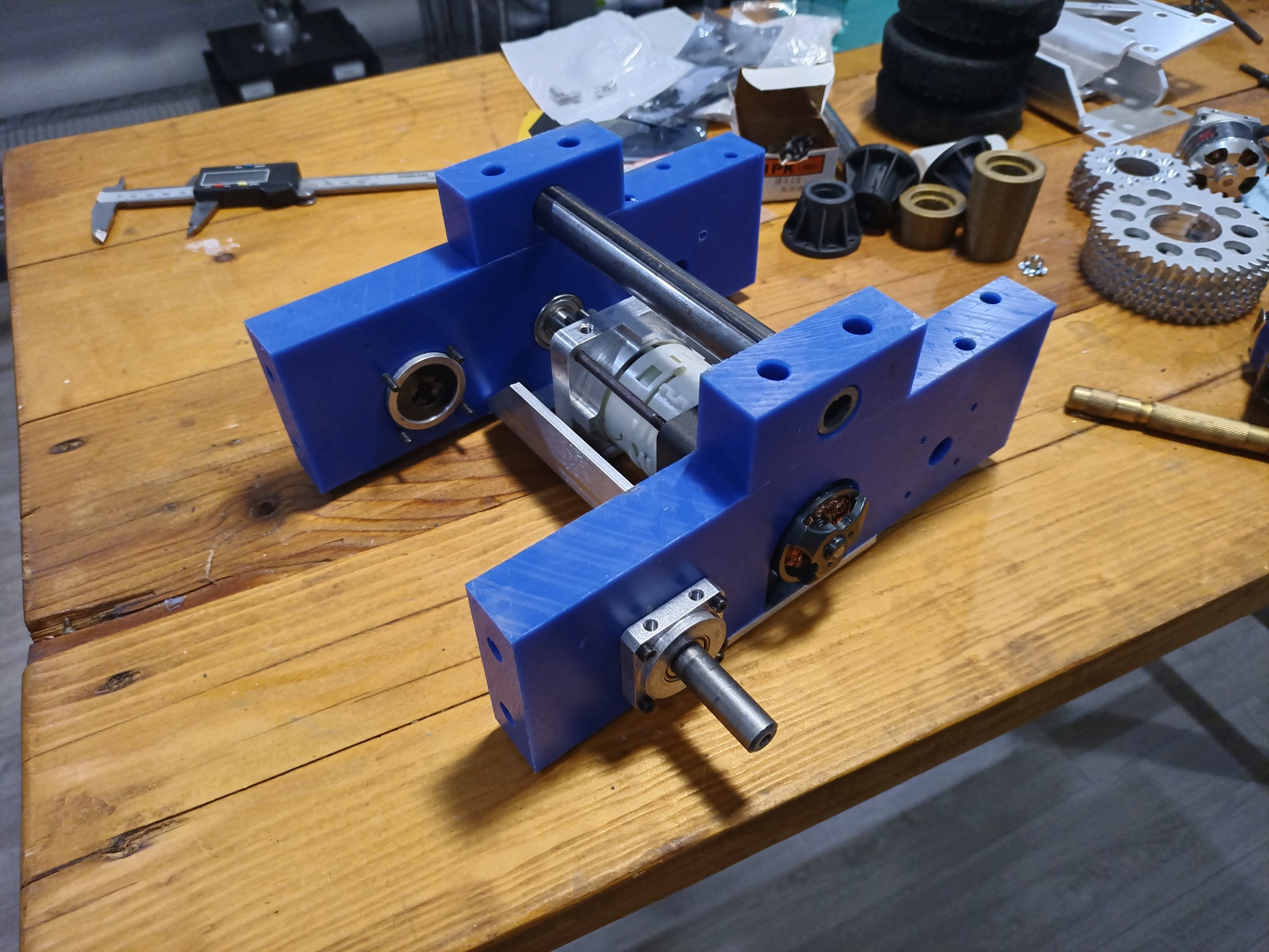
Very quickly, the bot reached the integration stage of the build. In the grand scheme of things I build, this is probably one of the most brain dead simple things, which is quite nice for a change. It means it should keep working. Right?
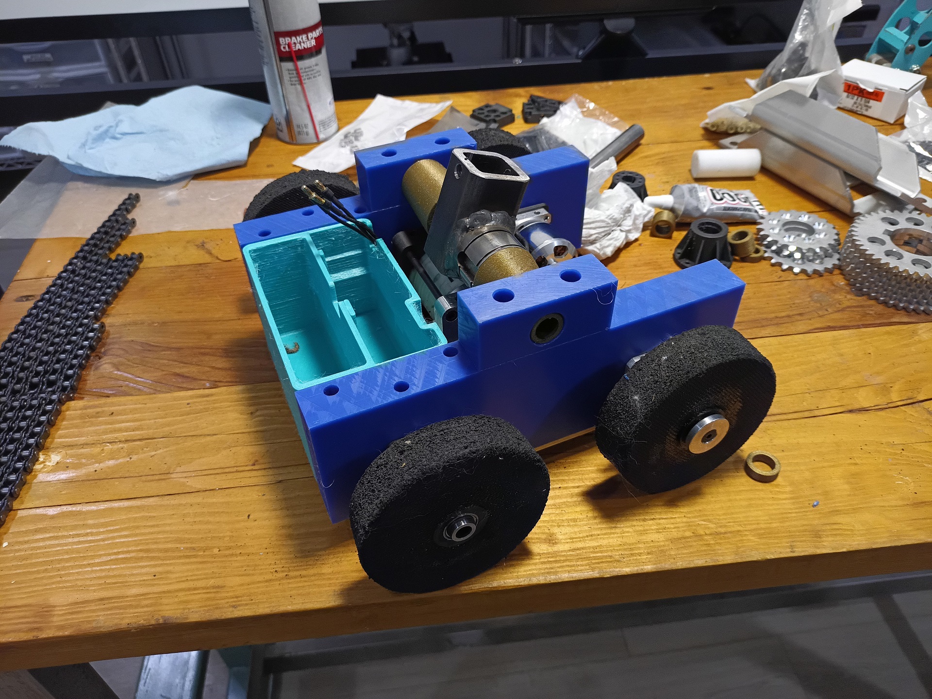
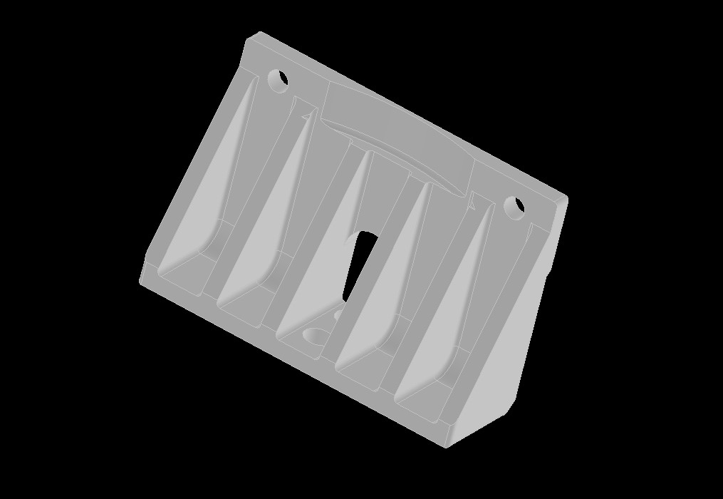
While the machining was happening, the Main Bracket™ was finishing being squirted out of TPU. Much like Main Brackets of yore, it holds the battery in the rear pocket and the ESCs up front. The “power switch” is the good ol’ just unplug the battery (pretty much banned everywhere now, I think) but Dragon Con badger don’t give a fuck.
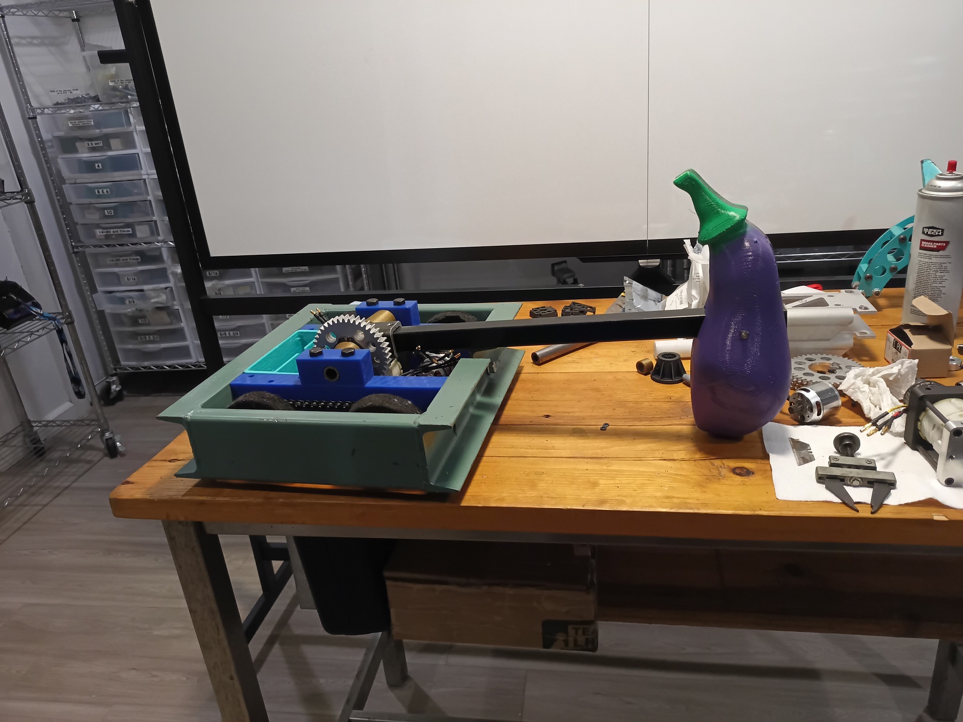
And really… that’s about it for the mechanicals of this bot! The drive chains started out very tight because of the unfinished edges of the sprockets, combined with my “Ideal Center Distance Plus Like 5 Thou” spacing of the axles. They’ll find each other over time.
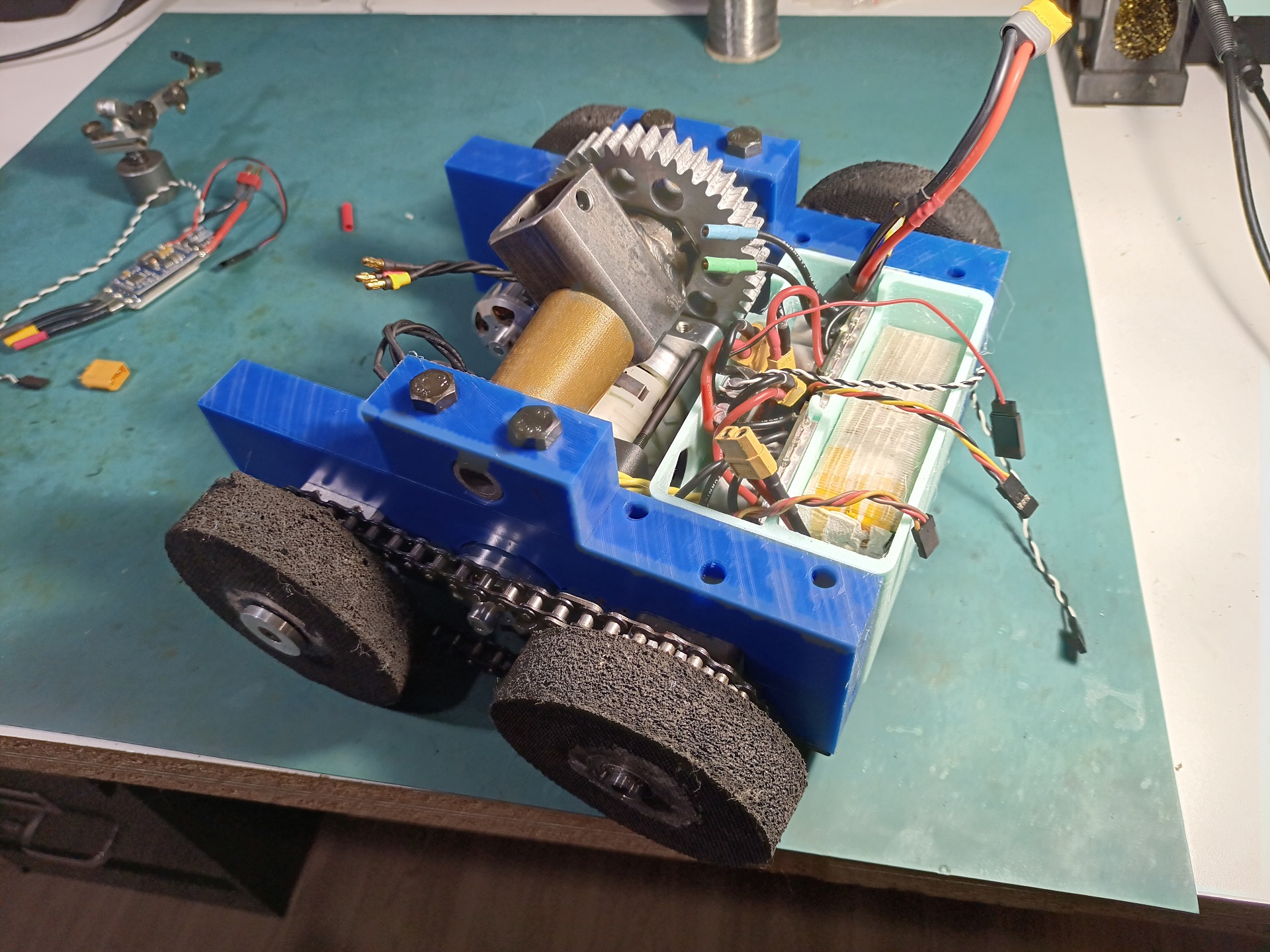
Wiring was largely ported over from the previous build with some connector changes and splices. The Brushless Rages are the size of suitcases compared to modern AM32 controllers and made wiring more difficult than it had to be. I did pick up a slew of sample AM32 ESCs off a few vendors after Dragon Con, so it’ll be part of the future changes to mess around with them and see which ones I like.
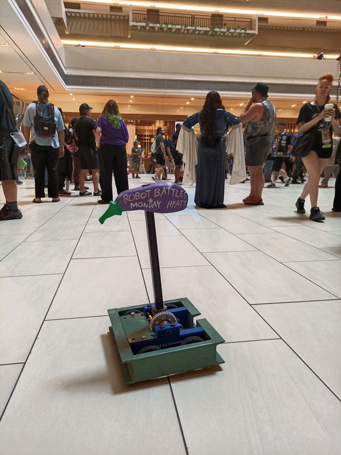
Boxcar 2025’s test drive was simply me bringing it to the con on Sunday and driving it around with an advertising message written on it! I went around menacing the other droids and R/C models. By the end of the day, everything had “worn in” enough to be smooth. So this thing was fight ready for Monday!
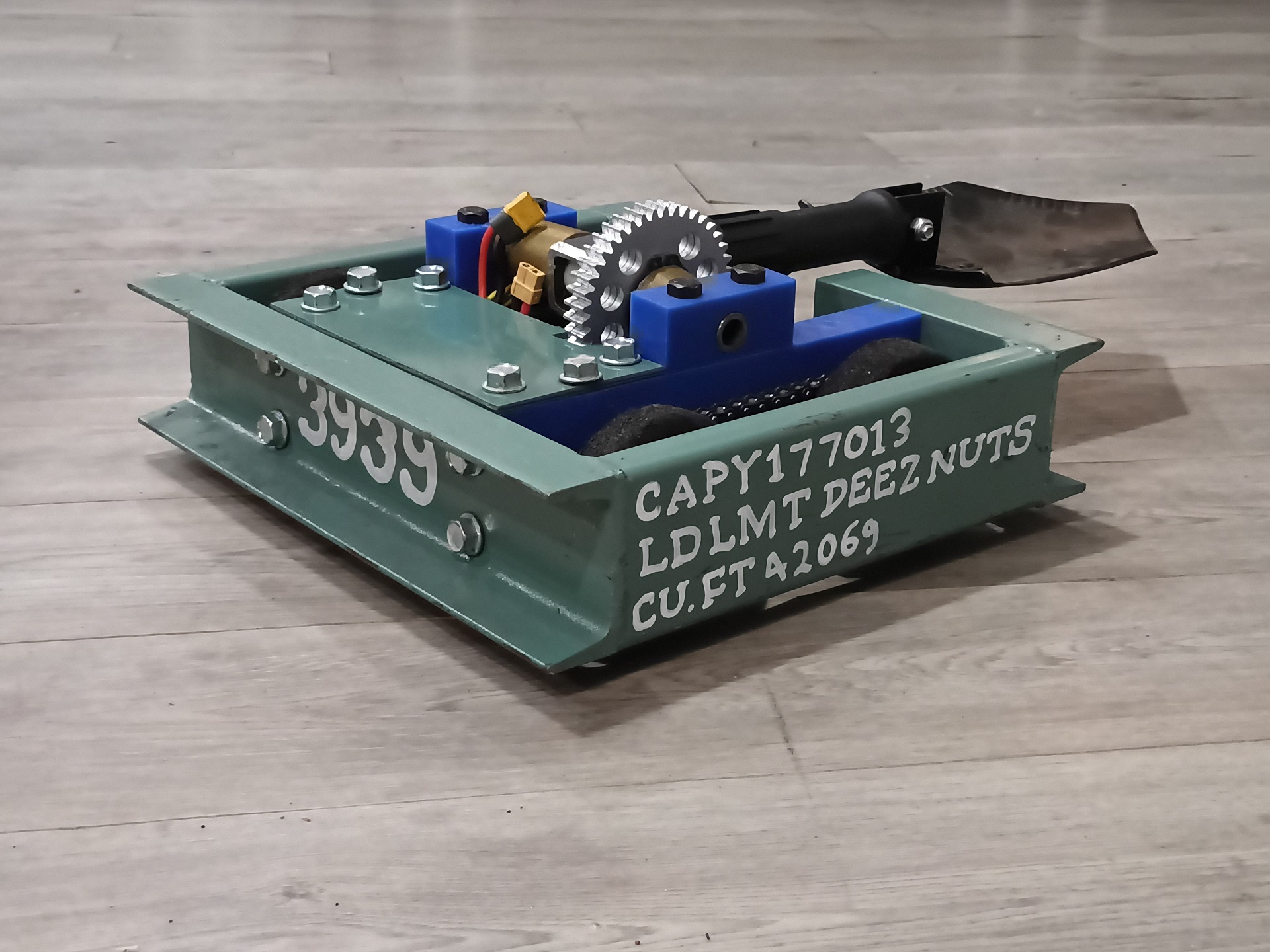
Here’s the “press photo” of the 2025 bot. At the Robot Battles on monday, it started becoming a new meme with the audience repeatedly chanting “EGGPLANT” whenever it was on stage. It left the event working, and would be entered almost unchanged in Motorama 2026…