Operation Bad Timing II: The Soundtrack; or Zen and the Art of Van Maintenance

It all started with a timing belt inspection.

With almost 230,000 miles on the clock now starting from its 151,000 mile humble beginnings, Mikuvan is essentially a cultural institution in my sphere of influence. It’s just assumed to always be around, and it really has been a relatively (emphasis on relatively) pain-free experience. Originally a hare-brained experiment in what if I built myself an electric car, which I swear to all of the gods who made themselves known these past 2 weeks will still happen, it means I’m physically coming up on service internals I never imagined I’d have to deal with again, because… .and I quote myself out of context from 5 years ago, “It’ll probably last like 10,000 miles if that”.

I can’t find the damn figure on this website, but I know I said something like it.

Well, almost 80,000 miles later, here I am. Since the “Great Accidental Partial Engine Rebuild of 2015“, I’ve actually barely gone inside except to feed its increasingly untenable thirst for motor oil. That, believe it or not, was itself over 50,000 miles ago too (I have the service papers from that still – 178K!). The past abonormally-cold winter finally pushed a number of wear components over the edge, it seems, and I wound up after the cold season with an almost two-stroke-esque oil consumption level of < 400 miles per quart and a complementary vape cloud per start.  So you know something like this was coming anyway, just a matter of when and how.

(Oh yeah – I made a number of other deferred-maintenance level repairs when it got warmer, but those will need to be handled separately now!)

We begin on the night of June 28th.
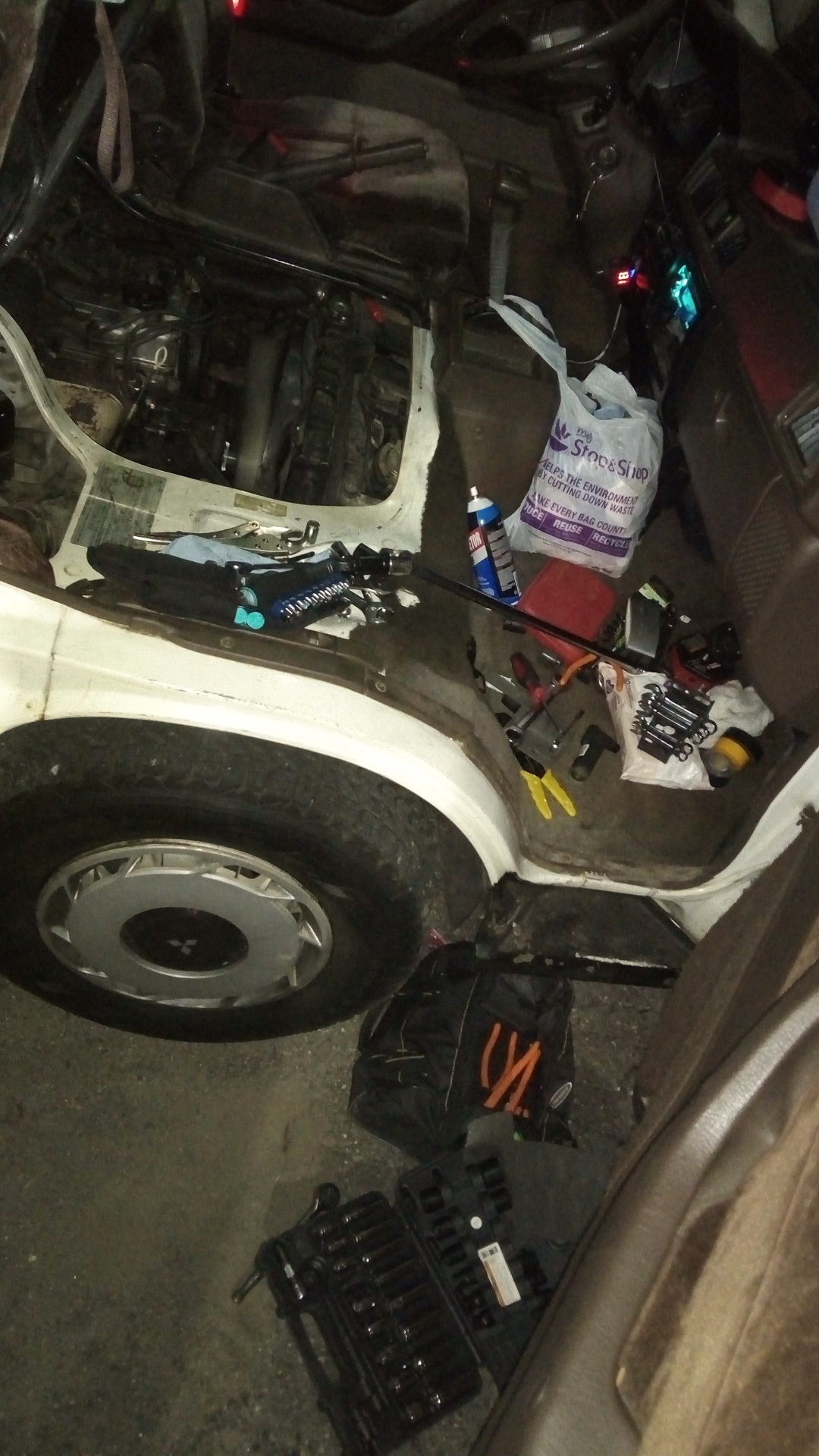
I was to leave for a weeklong southern-fried van adventure covering most of the Blue Ridge Parkway and Skyline Drive, and diving back to Atlanta through the Smoky Mountains forest roads, part of which I ran after Dragon Con 2016. Essentially wandering down in a casual manner for no good reason besides to be not in Boston, because every opportunity I have, fuck this place. The startup’s hardware status was finally to the point where I felt comfortable leaving it to the other members of the company (a story still building up which I owe everyone… put it on my I swear to God list); I’d already punted, up to this point, several of my usual trips because you don’t leave your hardware before it launches, like the opposite of a ship’s captain but with equal amounts of dodging icebergs.

So naturally, having experienced basically no van trouble in 2.5 Dragon Cons (my benchmark for “It Has Been ____ Days Since an Injury” of vans), it was almost a given that I’d make trouble for myself! Gee, I haven’t looked at the timing belt in a whole bunch of miles – let’s see how it’s doing.
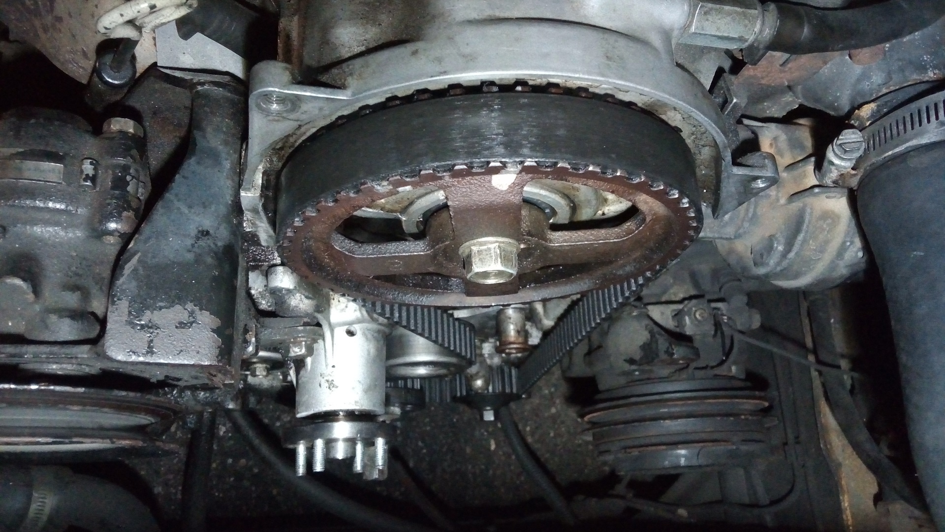
Yup, that there’s a timing belt. Hmm, it looks physically in good shape, but the tension is a little out since it’s worn down. So, how do I tension this thing again? Let’s not go back home to bring out the manual, or go upstairs to read my own damn blog post, and instead just take my best memory-stab at it.

You may be wondering How I ended up in this position why I chose to perform what to normal people and sensible mechanics is highly invasive, expensive, and complex engine surgery the day I was to leave for a multi-thousand mile road trip. Don’t question me – and if you did, I wouldn’t have a good answer. All I can say is since we did it the first time, I was confident I could get in and out in around an hour.

That was only a little wrong – there were a few stuck bolts in the way, which caused the procedure to take until after nightfall. Uh oh.

Alright, let’s see, how do you retension this thing? A quick gander at the online Ukranian-hosted rebuild manual gives me…

Cool, I’ll just loosen the tensioner and breaker-bar the crank pulley to move the timing belt 2 tee…. oh, shit, there’s no spring, that’s right. Mikuvan didn’t come with a tensioner spring – we always set the tension manually, and this was relayed to my van salon when they did the Great Accidental Partial Engine Rebuild. So they didn’t unbend some Smart Car’s front suspension to wind me a new spring either.

I immediately skipped several teeth on the belt.  It was then that I realized I was probably not going on my trip.

A sensible person would probably just Uberlyft home and try again during daylight, but I was already invested deeply into this rapidly sinking venture. Nope, I was gonna drive home tonight. I know this damn thing inside and out. I built it. I summoned it back into existence. So I stuffed the belt back on!
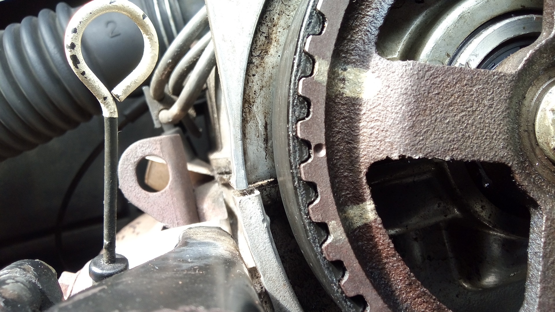


….and, in the dark, proceeded to misalign the timing belt by 2 teeth. Great! Non-interference engine, let me just pop it back over, right? An afternoon’s work to dig back in, right? Looks like I just aligned the mark we made a long time ago instead of the (impossible to see in the dark) factory-stamped timing dimple, right?
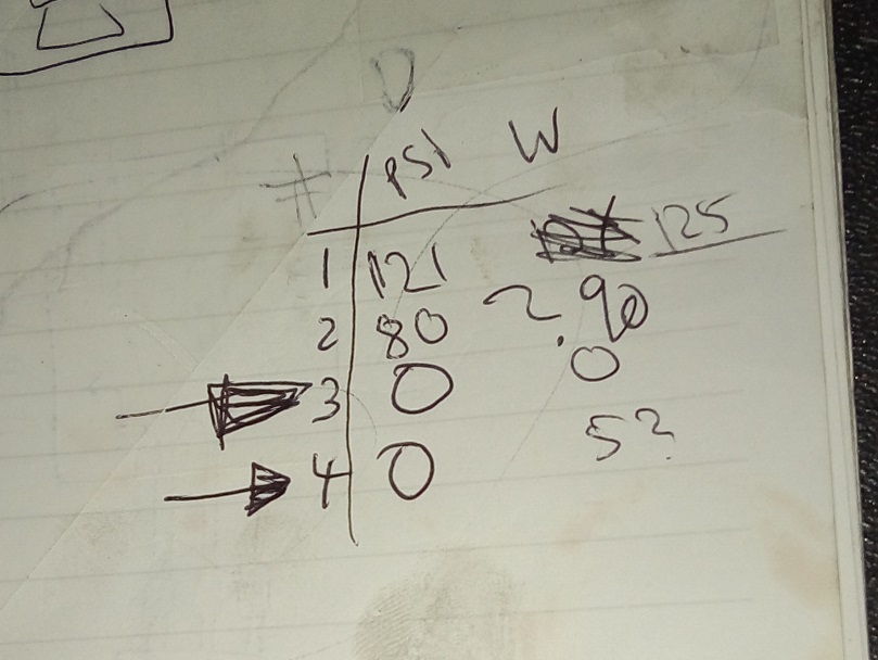
Sadly, the damage was done. The timing was artificially advanced by the belt misalignment, causing massive and horrible pinging (pre-ignition) as soon as I gave it any load; which only happened when I goosed it to get onto the main road.  It idled and crawled slowly out of the side roads fine, which gave me a false sense of security. I tried to limp it back as gently as possible, sounding like a diesel school bus the entire way. It’s interesting to think that if I had gotten it a tooth off the other direction, the timing would have been artificially retarded, yielding just horrible gas mileage and less power…..which I might have just wrote off as “eh, it always does that I guess”.

That’s it; I cooked my own goose. Until a lot of money was spent or time was used up, Mikuvan was down, possibly for good. With compression lost between two cylinders, it was clear that at least the head gasket was gone in that area, with possible piston and cylinder wall damage which often follows bad pre-ignition under load.

Let’s summarize the failure chain:

  1. I insisted on pressing forward with a complex and involved repair in the dark
  2. I checked neither my own documentation on the repair, nor the factory service manual for the entire service procedure, relying on memory of something I did over 5 years ago.
  3. I then proceeded to mis-remember the hardware configuration and performed a service procedure incompatible with the state I had left the engine in.
  4. Not stopping there, I tried to remedy it also in the dark, mis-recognizing an alignment feature.
  5. I also didn’t use a timing light or tool to verify that the timing was still correct – doing so would have immediately shown me that the timing was too far out of line.

The God-King had betrayed a fatal flaw, hubris; easy to taunt, easy to trick.

And so, on the morning of June 30th, when I was supposed to be carving up the Shenandoah Valley, Operation BAD TIMING II: THE SOUNDTRACK began. This was going to be deep.

It took me a while to decide to take on the task myself – I had an entire spreadsheet of options, from trying to source a junkyard engine, to buying an entire parts van (I had been stalking this Craigslist post for a non-running but good body condition Mitsubishi cargo van – the seller had sent me photos of it previously but I declined due to the price at the time), to just asking my van salon for an estimate “Make it Happen™”.

It was a hard decision, but performing this operation was to be a soul-searching mission for myself.

  • If I was so bad at paying attention to detail and glossing over important information to get myself into this position, what does that say about my leadership role at a company I co-founded to the people working for it?
  • Could I reasonably scope my work each day, seeing as how I can no longer just rail on a project until it’s done because of the need to ensure the continued operation of the company and development of our hardware? This might be the newest thing for me, honestly, having to adhere to a regular schedule not just for myself, but for other people. I wanted to limit myself to only thinking and working on it during weekends and after the business day – vaguely defined for us, but still a block of time when everyone’s around – was over.
  • Will I be thorough in all the operations I needed to do to bring the engine back from an unknown damaged state, not skip steps unnecessarily and take shortcuts which will bite me in the ass? Will our hardware be subject to similar requirements!? How would I even know what thorough engineering and design is if I never do it myself?

Okay, enough mangsty philosophy. Time to mark all the connectors of the ECU harness and little hoses and start stripping things down. My goal was to get to the head gasket itself by the end of the weekend.

By the way, if you ever need to rebuild a Mitsubishi 4G64 SOHC 8-valve engine in a truck/van application, here it is in all its gory, bloody detail. There’s quite a lot of English-language information for the JDM/international Delicas, but actually not much information for those who own the USDM vans since they are substantially different. Since I’ve been saved by my own blog posts a few times, consider this also an entry into the annals of “how to unfuck your van” for the owner community.
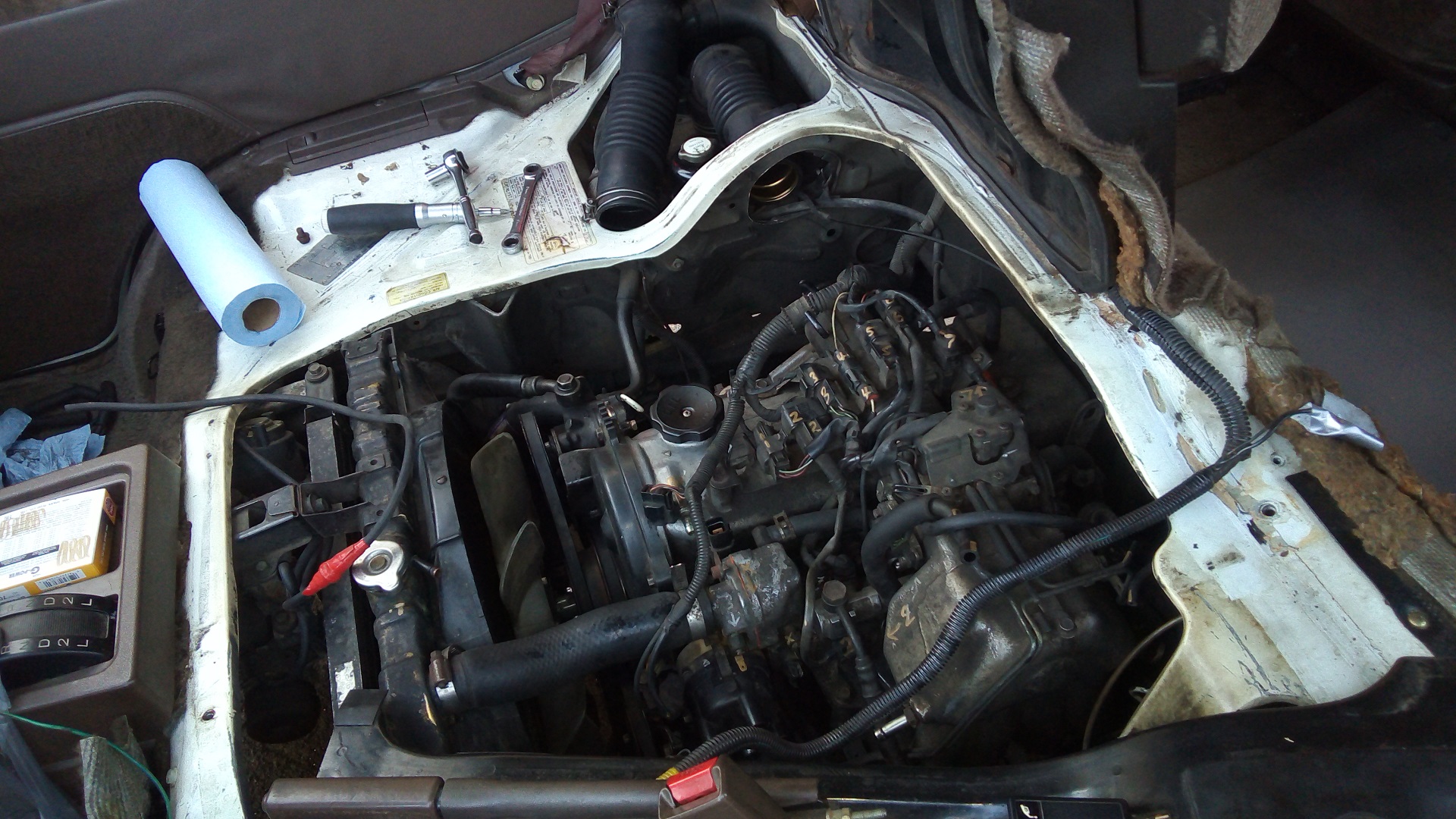
I marked literally everything. I had watched some of the action when the guys at Smooth Automotive were taking the head apart, and they said to me that really if you look at it, everything goes together in one way only. Yeah, sure, all the connectors are unique and they have logical wire lengths which can put them only in a few spots. But there’s a lot of them. That’s scary. I never touched Mikuvan’s engine harness for this reason, because at the root of things I’m still not a car guy by historical experience. Honestly, it took a year of wrenching on vantruck to get me to this point where I just sighed and said yeah, it’s just like the FiTech rig but spread out over a few cables.

Really, it wasn’t so bad after that.
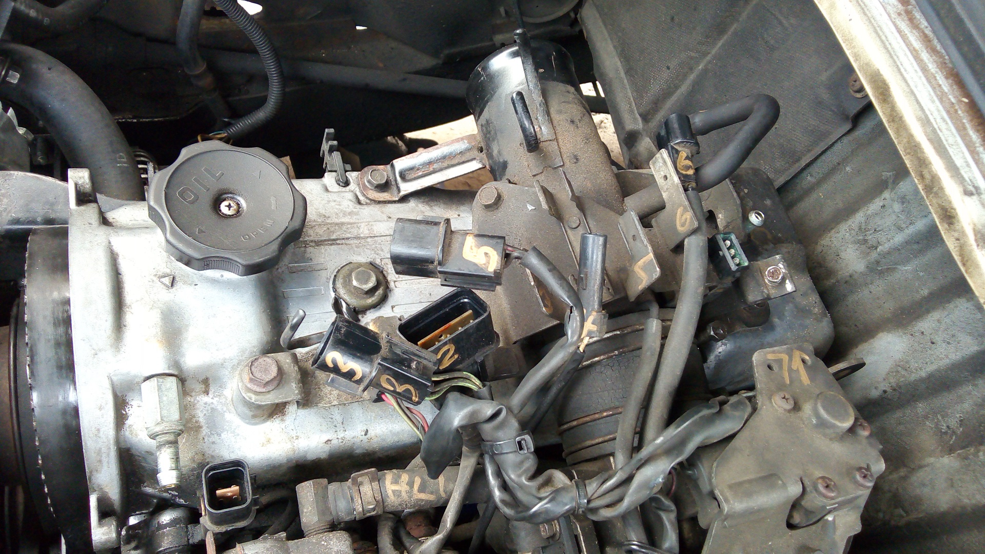
It was in doing a lot of this that I finally recognized where a lot of the EFI-related parts on Mikuvan were, which I learned on Vantruck performing the EFI conversion. I had only otherwise inklings that yeah there’s a throttle position sensor and idle air control servo and breather tube and manifold absolute pressure sensor and eeeeeeeeeeeeeeeehhhhhhhhhhhhhhhhhh. As it turns out, too, it does actually have a EGR valve – I had assumed the California emissions versions did but Federal did not, because the EGR valve was always shown in the manual in isolation, and when I felt around the area of the head I thought it was in, it wasn’t there, so I wrote it off as nonexistent. You’ll love where it actually was.
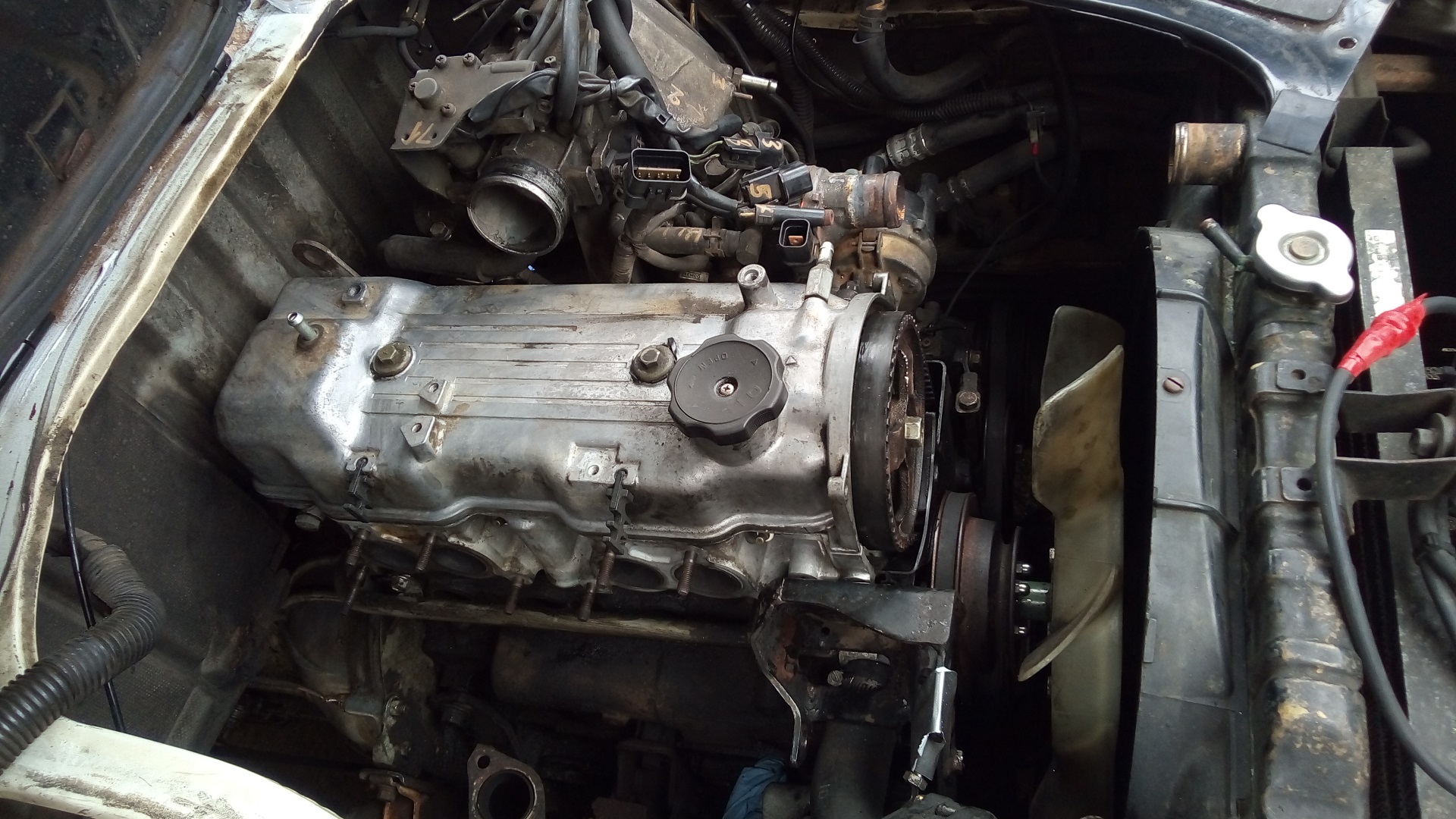
It actually only took an hour to get to this point. after pushing the connectors aside, disconnecting the throttle and transmission cables, and removing the multi-purpose brackety thing on top of the valve cover. A real mechanic would laugh, but remember, I erred on the side of cautiously labelling and marking (and taking photos!) for reconstruction ease later.

I also went ahead and removed the exhaust manifold, which was 1. cracked severely, and 2. took another half-hour of gently massaging and milking stuck nuts and bolts. Any antiseize lube I put on those threads has long evaporated.
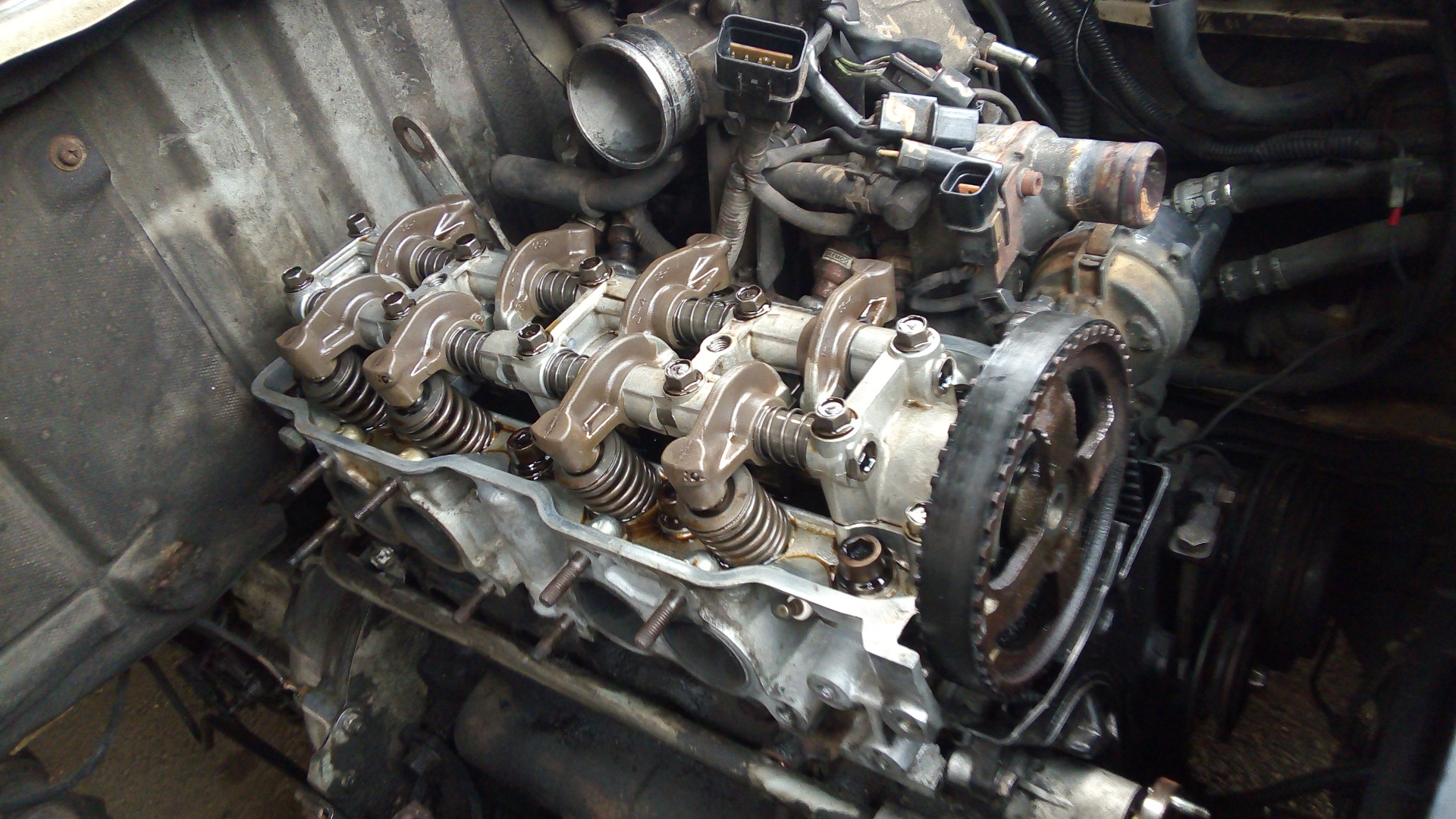
The valve cover comes off after its two bolts are loosened. Most of the gear up here looks relatively new (since Great Accidental Partial Engine Rebuild, or GAPER….what an unfortunate acronym…  involved a head rebuild) despite the operating condition of the engine since I pretty diligently perform oil changes and whatnot.

How do you change oil on an engine which eats a quart of it every few hundred miles? Well, you keep it topped off and after 5000 or so miles, you do it anyway. Just adding more oil all the time doesn’t make existing grunge go away .
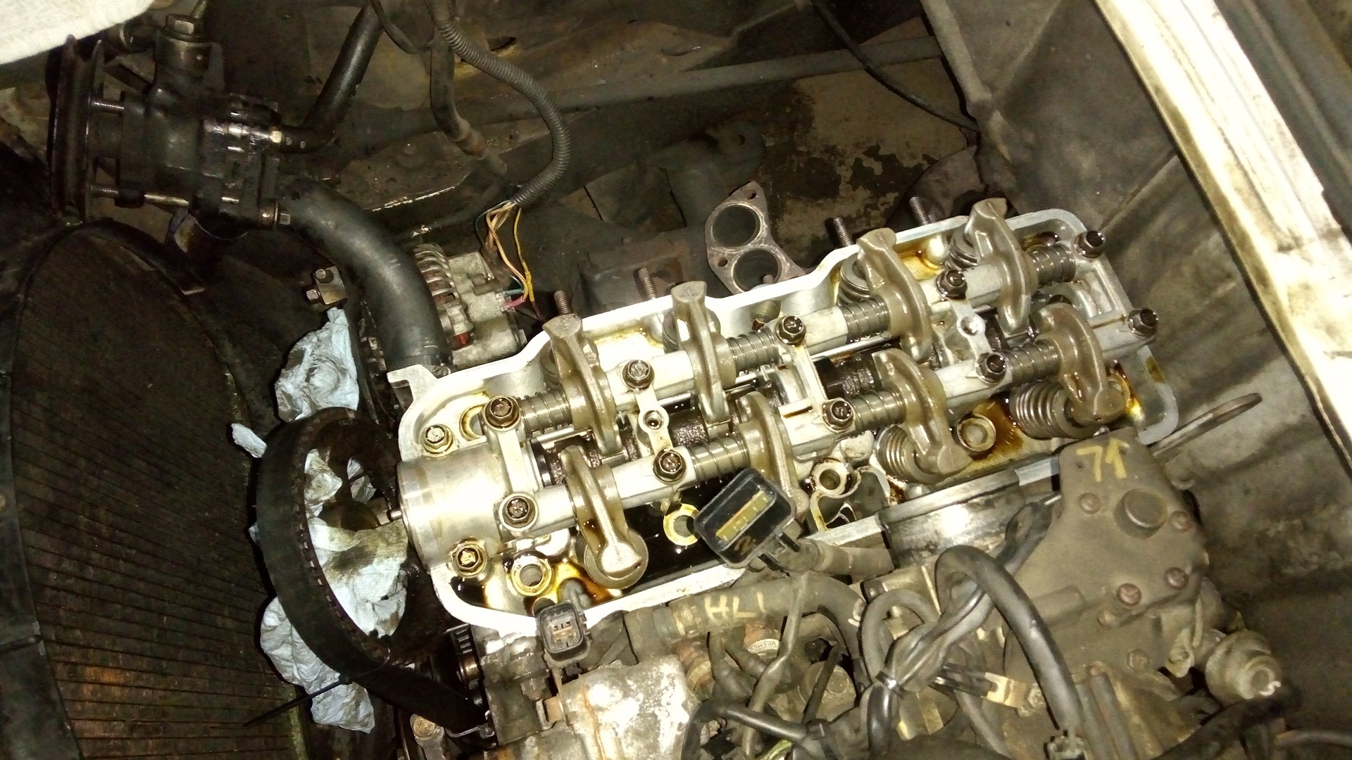
 

Ten giant socket cap screws later, and the head is ready to come off! This is the only place I’ve found on the whole powertrain which uses socket hardware. I wonder why? They’re M12 fine-thread screws with a 10mm socket drive.
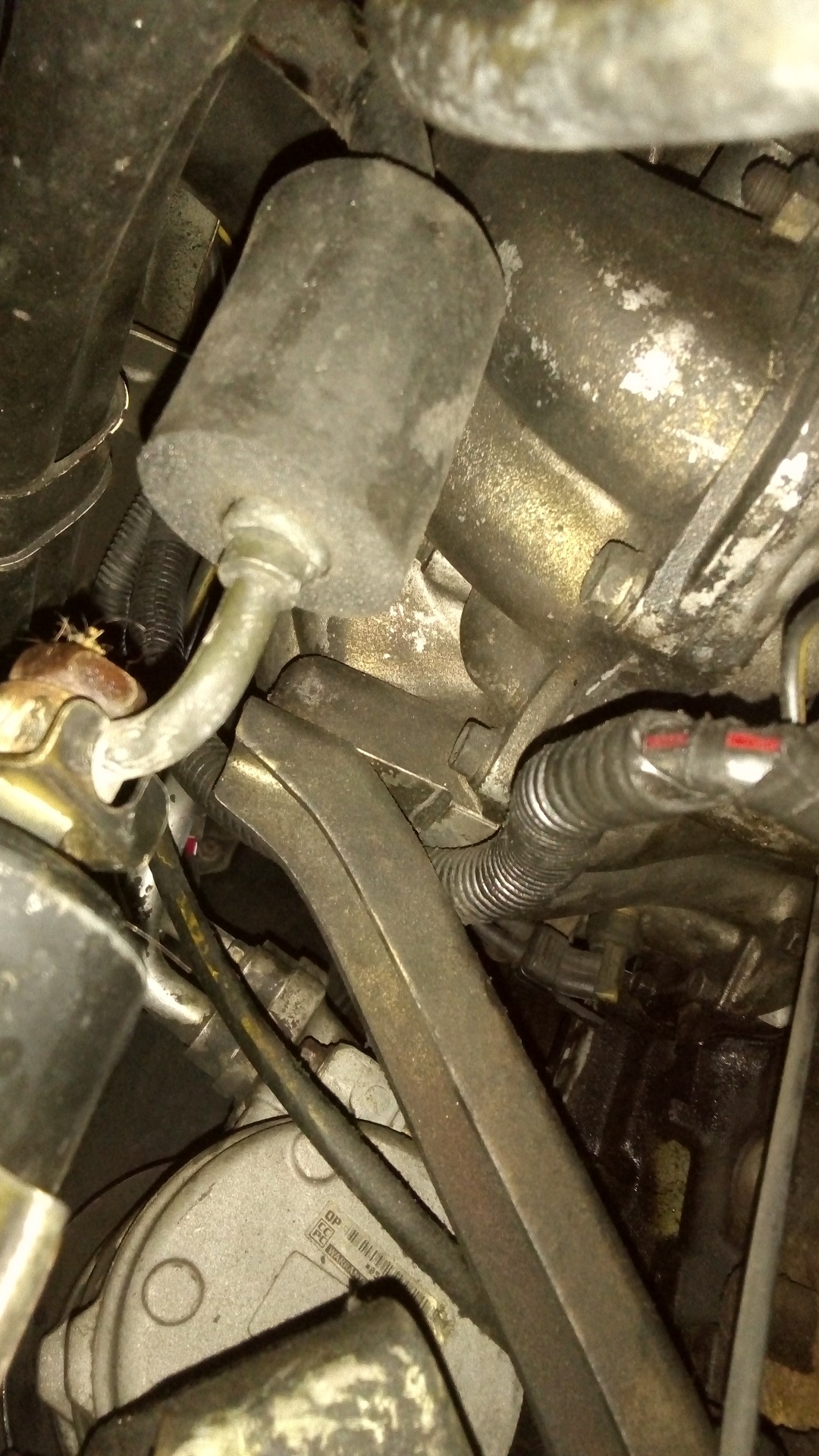
 

Actually, wait up. There is a Bracket of Irritation directly under the intake manifold, seemingly there to give it more support, which is NOT DOCUMENTED in the USDM factory manual, as far as I can tell!

It took 10 minutes of gently prying at the head before I finally figured out that something was causing it to spring back each time. This 14mm-drive, M10 bolt is accessed from underneath and behind the suspension/engine mounting member. Just stick your arm behind the driver’s side wheel and poke it upwards past the fuel filter.

(Remember: I have no lift or hoist system, or even a garage. I’m on the ground in a gravelly, disintegrating parking lot with jackstands only as a means to lift the whole thing. This is literally “How to un-fuck your van in the most painful, laborious fashion possible”)

Alright, now the Bracket of Irritation is free. It’s time to yank the head assembly off and…
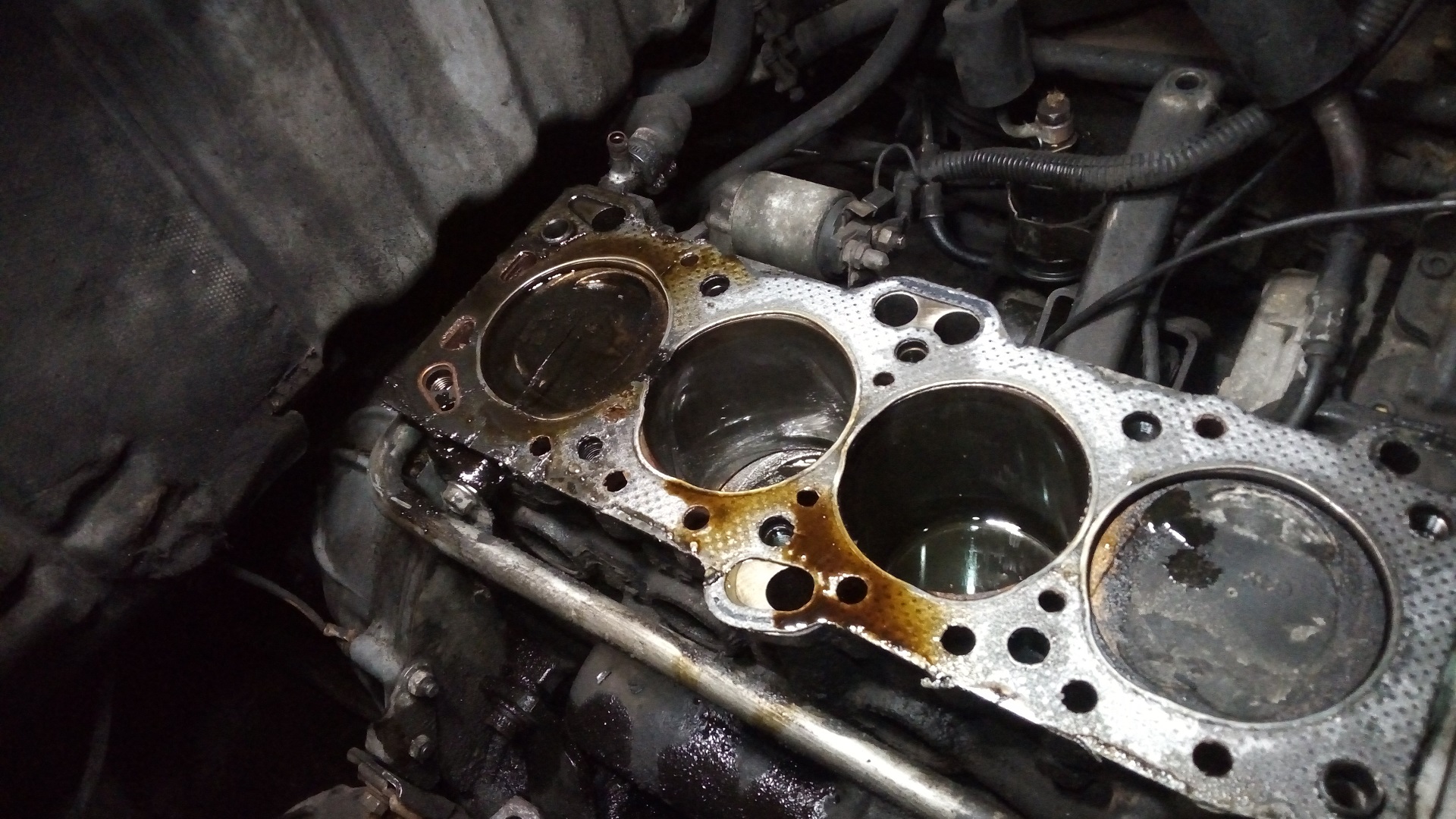
Yup, that’s a head-gasket alright. As I suspected, it blew out between cylinders 3 and 4, most likely as a consequence of severe pre-iginiton under load.

I’m not just out to stuff a new one on and call it a day. I’m told that once an engine fails due to pre-ignition, everything inside is suspect, from pistons to rings to bearings. It was on the docket while I was deep, brah to go ahead and pull the #3 and #4 pistons associated with the failure plus #2 which showed low compression and inspect them thoroughly. The worst thing would be to bodge it back together then have pistons implode later.

#1 still showed factory-spec compression, so I decided from the get-go to leave it alone. This actually means I can use my leftover 3 pistons from the GAPER (…what an unfortunate acronym again).  I ordered a new set of both crankshaft and connecting rod bearings just in case.
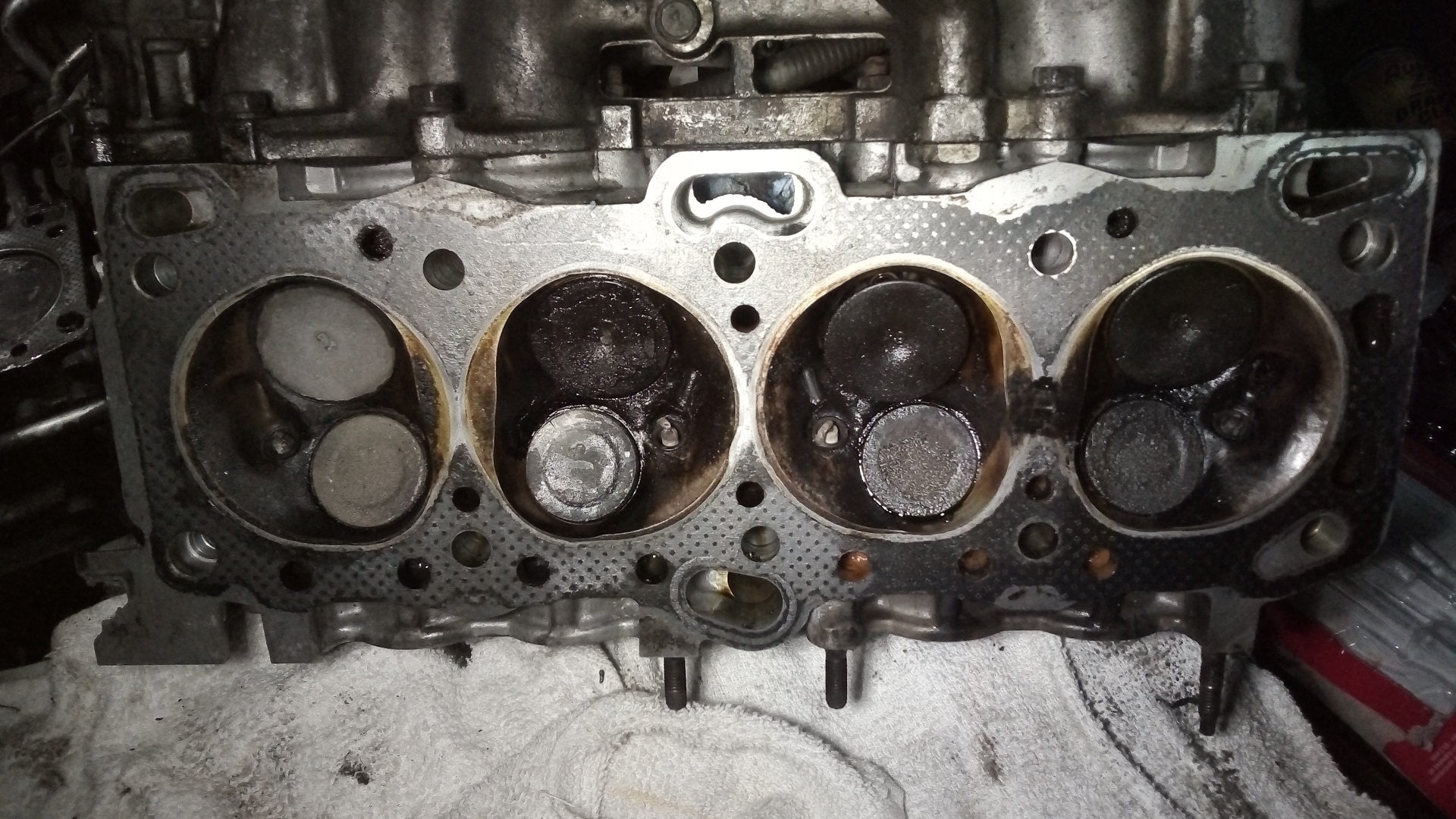
It seems that cylinders 2-4 have also been burning oil for a while, with #2 being the worst. I suspect it began in earnest late last fall into winter (which was a fairly unprecendented cold one) when I really started noticing smoking on cold starts. Yet this damned thing took me to Atlanta and back in January, and regularly got hooned around town thereafter and I didn’t even notice any power loss.

Call me silly for going back on my EV conversion word this many times and digging this deep in to ewwww, internal combustion, but something this hard for me to kill kind of deserves my best shot at getting it working again, eh?

So on the docket for this guy was cleaning the valves and seats (no regrinding or re-lapping, which I declared out of neckbearding scope unless I found serious damage) and new valve stem seals, which were clearly not very seal-y any more. I don’t know what a typical “old car rebuild” service interval is, but for the wear parts to let go after 50K is a little disappointing. However, I also don’t know what the gold standard of the time period was – maybe 50K per comprehensive service was actually phenomenal in the 1980s?

Nevertheless, it was time to clean everything up, scrape the old chunks of gasket off, and put the patient on the operating table.
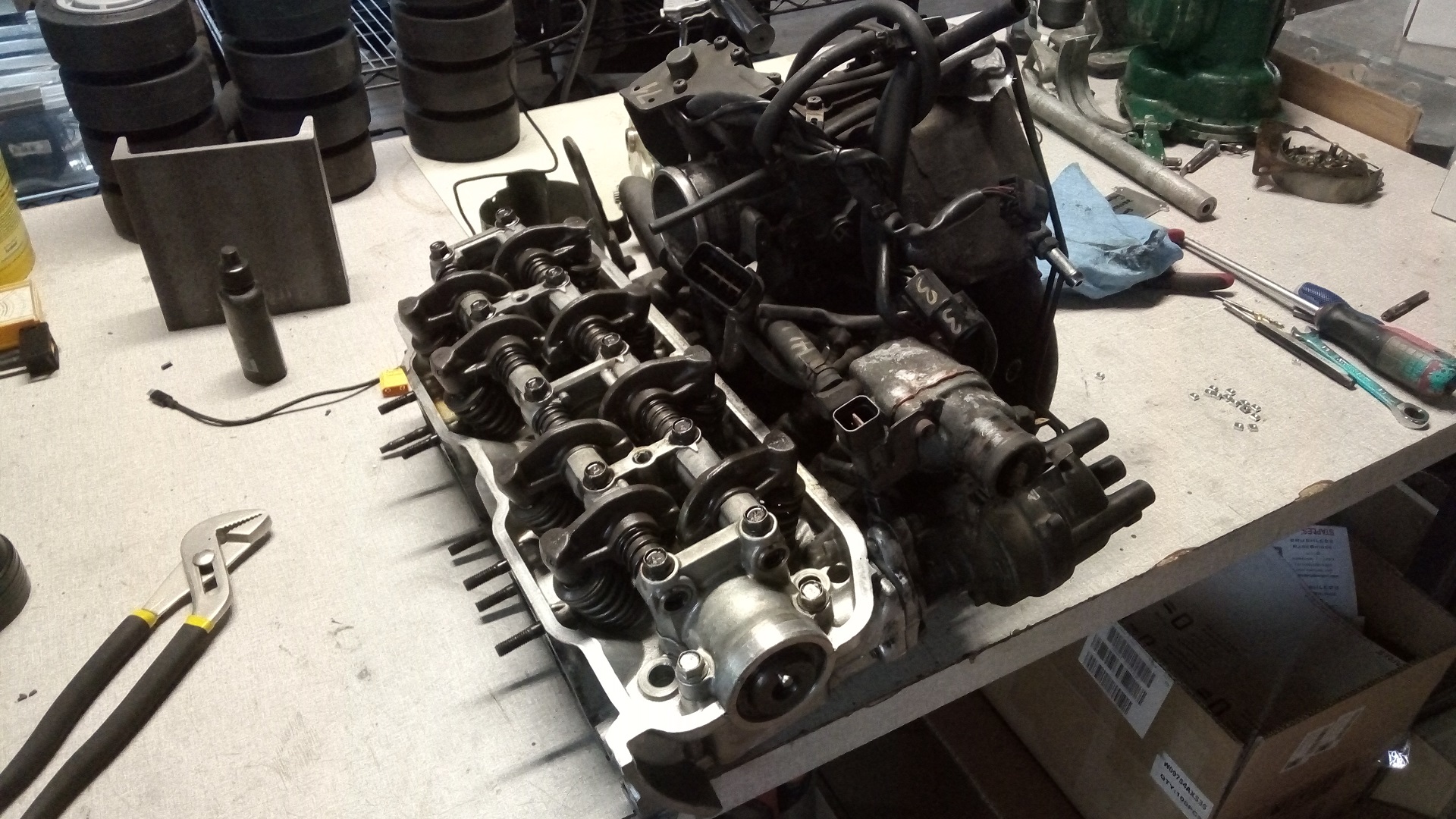
Around this time, I found a resource which, if true, could be a boon to USDM van-mongers.

A complete Chinesium head assembly for the 4G64 8-valve SOHC? Sure, why not! These engines’ bloodlines made it all the way up to like, last year in a few Chinese car models, and still live on otherwise as industrial engines for forklifts and generators.

I was now determined to do my usual exploration of resources for the greater good of the community. It also offered me a backup solution (if true) in case my head repair failed or I discovered some kind of terminal damage that is beyond my skill and resource to fix correctly.

I hit the button on this order on Sunday afternoon, and soon, the thing was due in on Friday after July 4th. What’s actually going to be in the box!? Hell if I know – if I received a Chinese junkyard head that got run through a dishwasher, I was gonna be happy.

Coming up next: Diving even deeper into the valves and pistons themselves.


What’s Inside that Surplus Center Bomb Hoist Motor? A Quick Break from BattleBots with Beyond Unboxing

Hey everybody! I’m back with a new episode of Beyond Unboxing focusing on a very unique piece of hardware that I just got way too curious about. In searching for a small American separately-excited (SepEx) motor, I remembered an item I saw on Surplus Center quite a while ago that they seemed to have a lot of trouble selling.

Huh. With no datasheet/manual/pinout available, the odd form factor, and shipping being extremely expensive due to it being heavy, I can see why I think they’ve only managed to sell 5? within the past year. To what other crazy dumbasses, I wondered. This motor definitely had at least 1 of the characteristics I was searching for – it was very American indeed, what with being American made for the American military to drop American bombs – and this will come into play later.

As for being sep-ex, I was at least very convinced it was a field-wound type motor, not permanent magnet. It seemed juuuuuust old enough that permanent magnets wouldn’t have been cheap in that size and not offered as much performance as a big series field winding in the required application – winching something. The multi-pin wiring harness coming out of the motor also indicated a wound-field type to me, since I couldn’t imagine this motor having an encoder or temperature sensor. Perhaps 2 of the pins were a load-holding brake, since hoist and all. But that still left at least three pins!

Not even mentioning the odd lobular shape of that gearbox of course – that got me even curious-er about what went on inside. Just looking at the thing, I counted at least 3 stages of gearing mentally, and with the weight of the whole assembly, there must be some seriously massive gears inside! So I went ahead and purchased one, just one, for merely 40% of the final checkout price as shipping this object was $75 alone. This better be really good…

Aand I’m glad to say that it WAS VERY GOOD INDEED, a journey into a vestige of the big & brute force style of American manufacturing where the product is an engineering textbook in physical form, and containing quite a few pleasant surprises. MURICA ONWARDS! Also, I managed to trace out the wiring for the motor, so there’s that.

First of all – They’re serious. It’s heavy. There was an attempt at shipping it correctly, for sure – the thing was firmly pallet-wrapped to a piece of thick particleboard on the inside of the box which had kinda survived transit. There were several holes punctured in the box also.

I wasn’t worried for it at all, obviously. I was worried more for what it took out on the way down the conveyor, like borderline expecting to pick the debris of someone elses’ Amazon sex toy order out of the motor fan grille level of worried. Luckily, my fears ended up unfounded.

It took… some effort to get this damn thing on the table. That’s an 18″ (0.5m) ruler next to it… the whole assembly is over 2ft long end to end. That’s a lot of little safety wire too, all neatly wound and tied off.

The motor has a nameplate on it showing it was made by the Steel Products Engineerng Division of the Kelsey-Hayes Wheel Company. Looking up the latter, I saw that they did indeed make many wheels, among other things – certainly during any of the 20th century war efforts they would have made military gear.

I back-searched the order number found on the motor and gearbox plate AF33(602)7109 and found some listings for a canceled defense specification from 1982 – so this would probably imply the units were manufactured well before then. Searching out that Mil-Spec MIL-H-25205A(1) showed that it was published as early as 1960. And searching the NSN (NATO Stock Number) 1730-203-8712, in the form of 1730-00-203-8712 yielded a 1963 date. So it could mean these things were built around the Vietnam War era.

Most of the info I could find was buried behind spammy paywall websites that aggregated mil-spec info. I wasn’t in the mood to research out the history of this damned thing, just to take it apart and see if I could use it for unintended purposes. I’m guessing after these were all decommissioned, they got stuffed in a warehouse in some recently-closed Air Force base before making it onto the surplus markets. Anybody who has more information on these, or if you’ve used one in real life, is welcome to tell me more about them! Would you recommend them to a friend?

The nameplate on the gearbox housing yields about the same information.  Based on my understanding from some light research, these were hitched to planes to lift bombs into position, but the planes did not carry them along for the ride. The numerous quick-release features and handles on it do imply this object was intended to be quickly moved in and out of position. I’m guessing the whole operation looked kind of like this, but I must balk at the unwieldiness of this device for such a purpose. Maybe 75 pounds is only heavy to me.

It is quite adjustable, however. The unpainted aluminum casting at the front pivots if you pull a pin, and can lock into one of six positions. The base has a pullable locking pin also, as well as four riveted shouldered sliders (two rivets visible above) so it was definitely designed to slide into something and lock in, then be removed quick.y


It also comes with accompanying toys – the tackle block and its accompanying 8-tooth ball-bearing-mounted #80 hard chrome plated sprocket, and its mating friend, an extendable wrench which fits into a cavity in the sprocket for when you need to give your bombs some manual assist. The fact that a #80 chain is the preferred hoisting medium still boggles me.

Let’s start taking this thing apart! First, there’s a spanner nut that retains the quick-release assembly which needs to be unscrewed. Absent the correct tool, I just used a needle-nose plier. The quick-release assembly has a 7-tooth #80 sprocket inside which has a splined bore for being driven by the gearbox.

There’s the drive sprocket. The chain enters through the vaguely H-shaped guide slot in the bottom of the quick release, and is fed into the sprocket and kept from losing contact by guides (and probably by virtue of being huge).

There’s a rotating cover of some sort which is retained by a pin – once the pin is driven out, the cover is removed and the sprocket is no longer being detained and is free to leave, thank you very much. Now you have a 7-tooth #80 sprocket to play with that fits on that specific type of splined shaft, which will be removed in due time!

I continued removing all the ‘jiggly things’ so they wouldn’t get in the way later. It has some other small clips and handles that all are held in by mildly press-fit pins.

Oh, and safety wire. Did I already mention all the safety wire? Everything is safety wire.  In beginning to remove the motor for my appraisal, I had to spend 5 minutes cutting and extracting all of the safety-wired screw heads!  I noticed the screws themselves were barely tight for the most part, with their only saving grace being safety wire. I assume this is not actually standard practice in the aviation industry…

All of the bolts are US threaded – they are generally 5/16″ thread, using a 1/2″ hex drive. Here we go! About to crack the motor off…

And let there be PEANUT BUTTER. There is a heavy grease packing inside which can only be described as peanut butter – it’s everywhere, and it smells straight up pre-EPA carcinogenic. You know that “Old Electrical Equipment Funk”? It’s that, but on anything it touches. I ended up digging a lot of it out with shop towels later and throwing it ot…. but part of me regrets it now and wants to keep the grease of the next one(s) I buy (if I do) in its own little jar for future generations to appreciate.

But here we see where I have already made wrong assumptions about this thing. I assumed it was a direct drive off the motor into the worm gearbox, or at most 1 stage of gearing. However, looking inside at this point, I see at least three stages of spur gears.  It’s interesting to note that I haven’t found a single molded plastic part yet – everything is rubber, phenolic, or metal.

Here is the motor by itself. I’m going to dig into this thing a little in order to find the pinout of the 5-pin circular military style connector, in the process discovering the type of winding it has – whether it’s series or shunt wound, or a seperately excited motor like I want.

First, four tiny safety wired!!!! screws need to be removed for the rear cover to pop off, which only houses a fan.

You may be wondering what that little “Westin Elevator Shaft” contraption is on the side. It’s a captive hex shaft which has a socket on the other end that mates to a hex stub in the spur stage of the gearbox. It seems like its purpose is to allow hand-cranking of the gearbox through the reduction the motor sees – presumably while your buddy is standing on the end of the manual tackle block tool also, so you can hoist bombs even when the power is out.

Another set of SAFETY WIRED!!! tiny screws and a shroud that covers the brushes is released. This doesn’t affect the brush holder – it only allows you to see into the ventilation holes. I’m guessing this motor might come in several flavors including open (like this) or enclosed/fan cooled (like it was before I cracked it open) depending on options.

The fan is retained by a single nut, and removing it exposes the part of the motor which I suspect was designed last.  So here’s what’s going on:

  • The outer ring of 4 nuts hold the whole endcap onto the tie rods that run the length of the motor. These are structural to the motor. They’re #10 thread, so a 3/8″ hex drive, except one by the Westin Elevator Shaft which is a “thin pattern” hex nut using a 9/32″ hex drive, probably since there isn’t enough space for a bigger nut.
  • The inner ring of 4 nuts retain the brush holder onto the endcap, and are #8-32 nuts, so a 11/32″ hex drive.

So there you go: 3 tools to do this operation, all within a few 32nds of each other. I was confused as hell about what was just painted over or not and if i was really seeing things or there were #8s and #10s in close proximity. ‘Murica


While I was undoing the endcap, I also unfastened the giant die-cast junction box and unscrewed the circular connector to try and find out if there were obvious armature/field wires. They all disappear into the motorial abyss, so I’d need to keep exploring.

Continuing with the theme of “no plastic anywhere”, all of the wire in this thing has braided insulation!

So I’m a wee bit confused on the order of operations needed to assemble this thing. I clearly did it the wrong way, which is to remove all of the endcap nuts at once and yank. The inner ring of nuts retains the brush holder and also locks it in a certain brush timing, which I will not be able to recover exactly.

What I think is the correct way to disassemble the motor appears to be removing the tie rod nuts (outer ring of nuts) and then removing both the armature and the brush/endcap assembly at the same time. That way, the brush holder isn’t disturbed, and since it’s a wound-field motor, you’re also not fighting magnetism to do so. Something to keep in mind for next time! I’ll show how to disengage the armature in a minute.

This brush setup is quite something. The brushes themselves are circular arc shaped and they pivot on little arms, instead of the traditional inline coil spring setup. Wonder why they did it this way? You potentially get more brush life from the small amount of space the other springing methods would take up, I suppose.

To pop the armature out, use a thin 1/16″ pin punch to drive the pin out of the pinion side. The pinion, it turns out, lives on another spline and the pin’s only for axial placement.

Then you yank. That’s a real pretty armature – it’s wound almost like a starter motor (which I suppose it will share a lot of intermittent-duty high-power lineage with).

Of note, it has a large flat steel faceplate. This is related to the next photo:

First of all, field windings and brush terminations! This allowed me to back-trace much of the 5-pin connector. I determined that the motor was indeed a separately-excited (Sepex) motor!

You see the fibery-looking pad at the bottom? That’s a phenolic brake pad. It’s spring loaded upwards naturally, and you pull the little pin on the right to engage/disengage it. It mates with the steel disc that is on the armature. When it’s engaged, the motor shaft is hard but not impossible to turn. It’s likely a load-holding brake for the motor and is there more as an extra precaution – unless that worm gear stage is very high helix angle, I can’t imagine the motor contributing all that much to load-holding versus the worm gear.

Repeat after me: “Reassembly is the opposite of disassembly.” I discovered that my “correct way” of disassembling the motor was in fact not going to be possible – there’s two attachments to the brush holder that are screw-in and must be obviously done so while the brush holder is not mounted to the endcap!

So the way I did this reassembly was armature, then brush holder, then the two screw connections, and then the endcap (then thereafter the fan shroud and so no). As for how the factory made sure the brush timing is correct…. hell if I know. I did my best by visually inspecting it through the vent holes.

You know what? Just don’t take the motor apart and take my word for it.

Since the motor was really my agenda, I decided to do some basic characterization of the motor. For my sepex application, I would like to know the field resistance, armature resistance, and ideally the magnetization curves of the motor – no-load voltage (out) versus field current for several different input speeds.

The problem was I would have needed a controlled way to spin the motor up to around 10,000 RPM, so I didn’t get any of the magnetization curve data for the time being. I found out that on its native stated specifications – 28 volts applied to both field and armature – it wanted to draw 6 amps spinning no-load at 9,200 RPM. For such a big motor, 9,200 is really fast…. but the 8,000 RPM @ 44A specification on Surplus Center made more sense.

I also solved the armature resistance to be 0.04 ohms and the field resistance to be 10.1 ohms. This is one hell of a motor – albeit only for a short period of time, which sounds perfect.

all together now… what the fuck is he building now that needs this specific motor? doesn’t he design motors for fun?

To summarize this section for now – here’s a pic of the circular connector showing the pinouts I discovered.

That ought to fix all the buyer questions on the Surplus Center website, and hopefully make this thing a little more useful if you have a #80 chain hanging around that needs something to climb up it slowly.

But the story doesn’t end there. Oh, it’s just beginning. There was still 30 or so pounds of gear that I haven’t even opened up yet.

I’ve already found that my assumptions about the input stage were wrong. What ELSE don’t I know about this? Let’s remove the 25 miles of safety wire that hold the back gearbox cover plates on.

I actually decided to work forwards from the motor and start on removing the worm gear stage first, since I got very curious about what kind of worm gear it was which they’d still warrant a load-holding system on the motor in the form of the spring-loaded brake. The six inner screws release a cover plate for the bearing of the worm wheel axle. The outer six safety-wired screws hold the entire endcap on; it’s a mild press fit, so be prepared with a sharp paint scraper or knife edge to do the initial release.

The worm gear system is now exposed, but it’s not yet removable since it doesn’t have enough slop in it to wiggle past the wheel past the worm.

The other side of the worm wheel axle is just the large back-side cover. Time to take all those screws out and start paint-scrapering to release the press/grease fit!

First off: Holy crap, that’s a lot of peanut butter. Second: Holy crap, that’s another entire intermediate stage I wasn’t expecting! Third: Holy crap, those gears have stub-form teeth! I’ve only read about that in engineering textbooks of my bunny days – never seen stub gears in real life before.

Once this back cover pulls out, by the way, the worm wheel just falls out the endcap side (bottom in this photo).

The worm wheel is kept in place by the compression provided by the spanner nut, but power is taken through an involute-splined hub. Notice the small gear stage next to it. This is a mere 1.25:1. The gear at the bottom of the worm wheel axle is 12 tooth and mates with a 16/12 tooth cluster gear which does the final mate with the large output gear. I must wonder what type of packaging concern or ratio fine-tuning warranted this intermediate stage when you theoretically could have tuned the worm gear or output gear one way or the other slightly.

The worm stage is a double-enveloping type, also called a globoid worm design, for maximum strength and contact area. This thing has just been an engineering textbook in a peanut-butter filled box so far; it was actually quite pleasant to see again, given my recent forays into electronics and shitty vans.

I sprinkled the final drive out of the casing, only to discover….. more peanut butter. Go figure.

What was also cool to see: Inch-sized big-bore thin section bearings. These days, the dominant bearing is the metric single-row series (6002, 6200, 6801, etc.), but there is not a breath of metric on any of this. The bearings all were crunchy – unsure if it’s due to aged and dried lubrication or just specified to be a lower uniformity/finish grade, but I’m going to yank them all off and keep them.

After I cleaned the peanut butter off for the most part, here’s the final drive. The output shaft isn’t actually retained by anything but the back plate – once it comes off, the shaft will fall out. It also isn’t carried on its own bearing, depending on the distal bearing found in the aluminum mounting assembly with the swivels that I removed first. So the green gearbox wasn’t ever supposed to live on its own either.

There was still a worm gear stuck inside and the 3? stages of initial spur gearing I haven’t discovered yet, so back to the other end we go! The same procedure is used on the motor side: cut off all the safety wire and just start unscrewing. This side has some dowel pin alignment mates which are more press-fit than the rest.

Aaaaaaaand more peanut butter. By this point, I’ve almost half-filled a 44-gallon rolling trash bin with towels full of peanut butter stains.

The setup didn’t make any sense to me, as I was clearly spinning the motor pinion’s mating gear by hand but seeing two different rotation speeds. In fact, the hex shaft which couples through motor into the (missing) manual crank handle is geared up from the handle itself, but at a different ratio to the motor which is geared down in two stages. They put a complete independent gear path in here just so you can spin it by hand – I’d like to think it was informed by how much torque it was comfortable to keep applying versus how quickly your arms get tired from cranking.

But it was probably because steel was basically free back then.

After another container truck left for the JIF factory, we expose the final boss of this gearbox: the screw holding the input gear on.

Actually, no. It was in fact easy to remove that screw, but hard to remove the two gears in front of the worm input gear. They’re just press-fits with bearings ,which I had to “three phase screwdriver” pry the upper right (motor input) gear out, and slide hammer the hex shaft gear out (attempt 1 with a vise grip is shown…. attempt 2 is hooking my slide hammer onto this vise grip) trashing the tiny inch sized angular-contact bearings in the process.


F :(


The input pre-duction has been freed!

….and there are more screws. And more safety wire. 2 health bars? Nope, this thing’s had like 20 extra lives by now.

After that gets undone, the worm gear pops right out! Hurray!

Here’s the final gear count: Seven, each intricately engineered and machined, with polished teeth and edges. Go watch some worm gear machining videos and then talk to me about how sweet this thing is. I’m not sure how I can even use any of these gears outside of the box they came in, because I sure as hell am never going to make the worm gear fit correctly in anything again. The temptation of bringing Cold Arbor back, though, went up several-fold after doing this surgery.

So what’s the ratio from the motor to the big 7-tooth sprocket? The input stages are made of two stages of 54:14 (14 tooth pinion on the motor, a 54/14 cluster gear, and 54 tooth worm shaft input gear). The worm stage is 30:1. Then you have the 1.25″1 intermediate stage (12 teeth on worm shaft onto a 16/12 cluster) and finally the 36-tooth output gear. That’s a total of 1673:1 and some spare change.

I’m inclined to say that this device is really best kept together, maybe with your own assembly in place of the swivel mount, and using the motor as-is also; maybe doing some work to adapt the input shaft to your own motor.

There’s so much excess it’s a joy to behold: In its day, steel was free, labor was cheap, and China wasn’t a real place.

alright, so what the fuck are you building that needs this precise kind of motor, the more American the better?

All will be revealed in due time, but it’s exactly what you’d expect. I’d like to collect some magnetization data on the motor soon, so I’ll report back in with its operating characteristics at several voltages and speeds. I’ll likely end up purchasing another one GREAT, MORE PEANUT BUTTER and making a face-to-face dynamometer to collect said data (maybe not full dyno curves, but at least the bemf-versus-speed info) since the best way to characterize a motor is to drive it with itself, in an electrically masturbatory loop of power.  I’m thinking of how I’d incorporate the rest of the gear stages, but it seems unlikely with the ratios I can arrange them in. All I can really say since I don’t have a definite timeline due to my startup-baby, is that it will bring some interesting new-old tactics into a game with an established meta; it won’t win anything, but will be glorious while doing so!