I’m starting to think that LOLriokart might be an ongoing project for the fall season. Reasons mostly revolve around increased day-to-day time constraints and the fact that it’s already mid-July. Ãœberclocker and Pop Quiz 2 take higher priority right now, since Dragon Con is at the end of August and I’m also heading back to Atlanta around mid-August, leaving roughly one month. Additionally, I need to start getting some green-colored ducks in a row for fall semester (something is surely amiss – they want me to cough up how much money!? In 3 weeks!?)
Shenanigans. Anyways, a 40 pound box of heavy industrial metal landed on my desk at the Media Lab today, and it was from Surplus Center. Inside it were almost all the necessary implements to transmit motor power to a set of drive wheels.
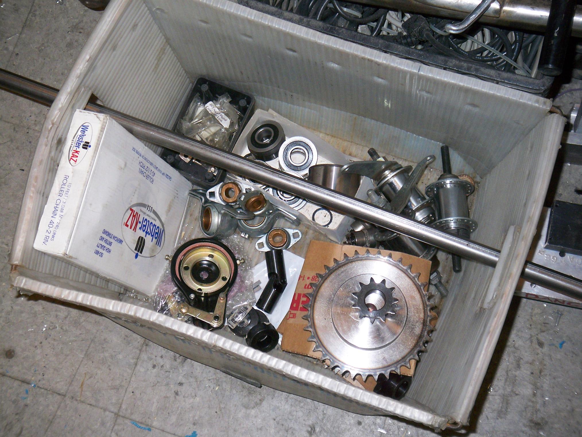
And so this is the cumulative pile of parts, including everything from today. Starting from the top left and orbiting counterclockwise,
- Battery bars from dissecting the large NiCd packs
- A 36″ long, 3/4″ diameter keyed shaft, the rear axle. Surplus Center stock item.
- A box of #40 double-row chain. Oops, when I saw “#40-2” I thought they meant 2 feet. Now that I check the Surplus Center catalog page, it indeed says #40 double strand, 10 feet. Questioning own sanity. I wonder if it’s okay to use half of a double strand chain.
- A gaggle of little flanged bushings. I got the smaller ones from SC at 50 cents a pop – they will most likely be mated with the steering shaft. The big ones were scrounged.
- Two band brake assemblies from small electric scooters. I had one a while ago, but it was significantly larger – I didn’t really expect these things to be so tiny until I actually got them in the mail. Fortunately, the front brakes are only for bringing the vehicle to a full stop, complementing dynamic braking, as well as locking the front wheels for epic burnouts. Nothing high-energy.
- A small universal joint I got in case I wanted a better steering position, from SC.
- 3/4″ shaft collars for the above rear axle, also SC.
- Epic #40 unbored sprockets. I knew #40 was huge, but I didn’t realize how huge until I found out each sprocket weighed 5 or 6 pounds, is .3″ steel, and 6 inches in diameter. I will bore them out for the 3/4″ shaft, but since I have no reasonable access to a broach, they might have gigantic set screws embedded in them. From where else BUT Surplus Center?
- Little #40 sprockets for the Etek, ditto.
- A cluster of bicycle coaster brake hubs. They’re probably not going to be used for anything. All of them were scrounged for some front brake ideas, but are now obsolete.
- A bundle of bearings. There are four 20mm ones, two bigger 20mm ones, four 3/4″ ones, and an assnormous double roller bearing of some sort. I forgot where the gigantic bearing came from, but it looks like a machine tool spindle bearing. The 3/4″ bearings were ordered from McMaster since I also have a 3/4″ shaft – the 20mms were scrounge, but would have required machining a giant steel rod down to match them.
This is some Serious Fucking Metalâ„¢. The only thing Surplus Center could have included to make it even more industrial is some Nine Inch Nails albums.

Experienced users of chain know that raw, unprocessed chain comes in cakes form, and must be baked properly.
Oh, wait, the caking is just from the fermented packing grease… I actually had to break the cake apart by yanking on the chains links. The chaincake is a lie.
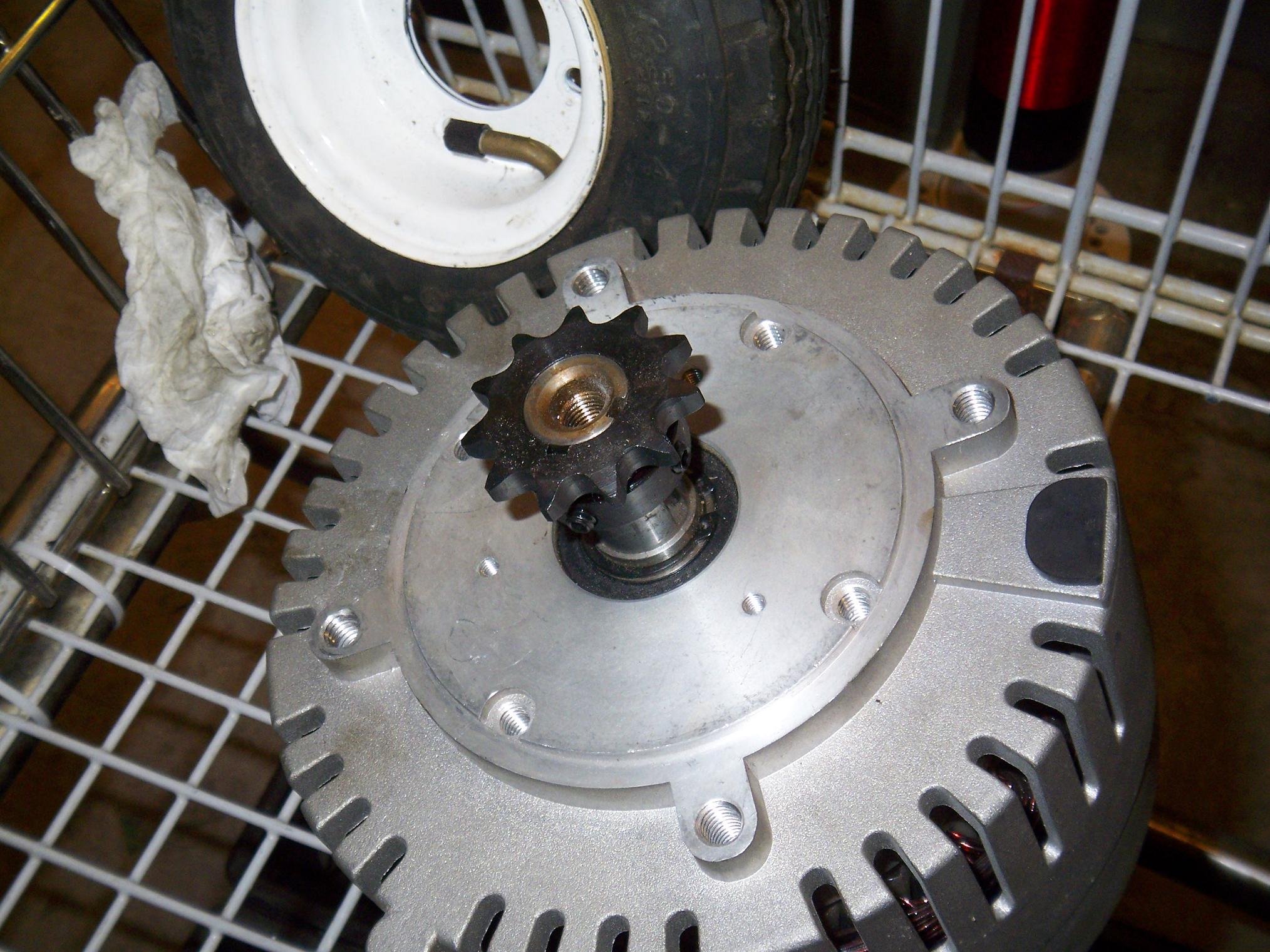
I was lucky enough to find matching sprockets for the motor, so these little sprockets require no modifications.
After sorting out the industrial grunge, it was time to turn my attention to design. The front wheels on LOLriokart have been a quandary for a while now. I wanted mechanical front braking since the motor controller can perform regenerative braking on the rear axle, and a mechanical rear brake would just be redundant. Also, mechanical front brakes means I could perform tricks that require weight shifting (e.g. initiating drift).
I went through a whole bunch of ideas, which are listed in an earlier post, but in the end, I broke down and got the scooter band brakes seen in the picture above.
Now the problem was implementing them. Their brake cups didn’t really match any of the other parts in terms of dimensions. Their bore was too small to fit over the stock bearing hub of the pneumatic tires, yet too thin to machine. The wheel hub itself didn’t lend itself to much OD modification as the bearings took up most of the inner diameter. I could make a custom hub, but that would require processing a 3″+ aluminum round, and with the horizontal bandsaw broken down at MITERS, that wasn’t going to be fun.
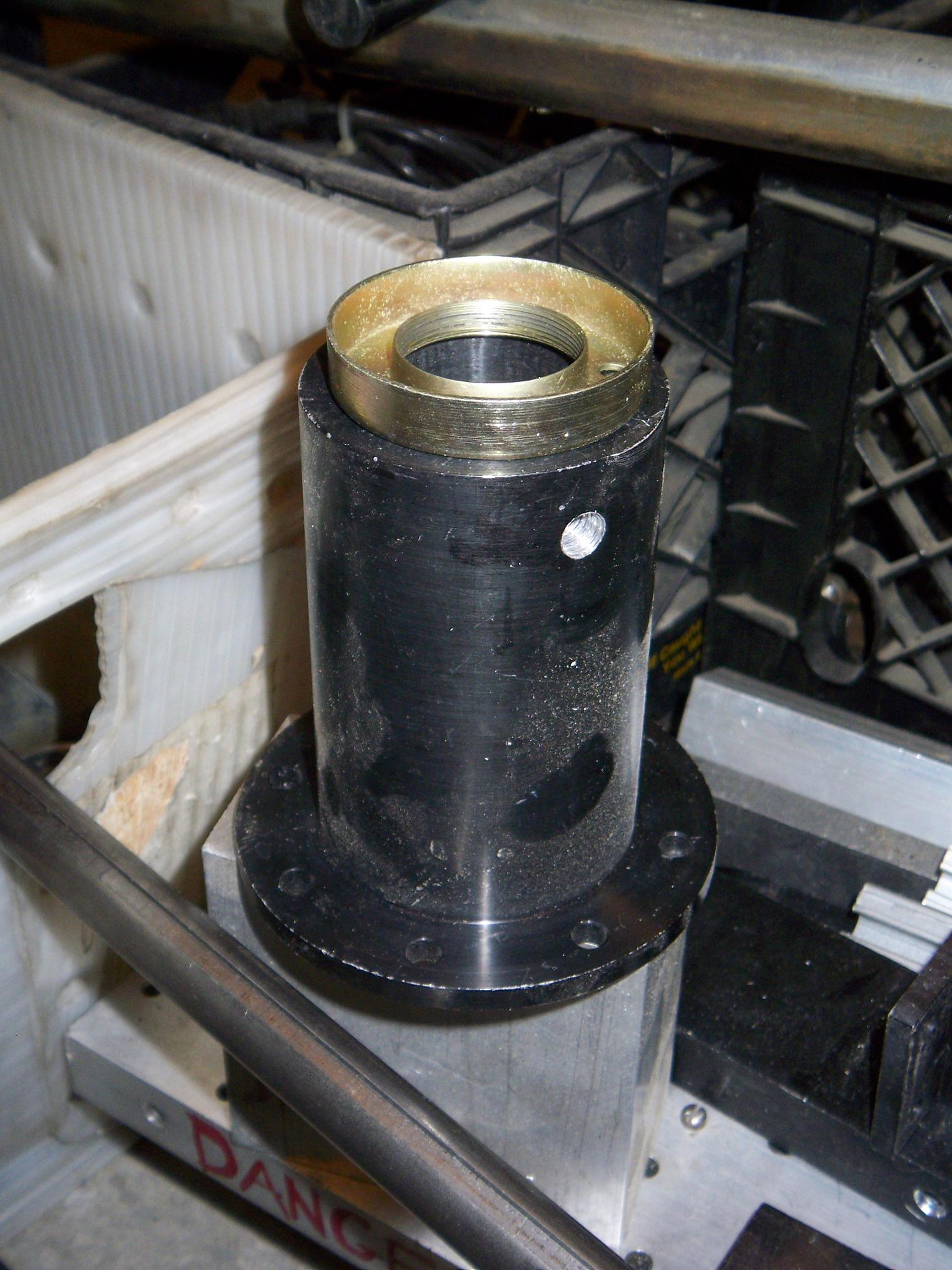
A solution had to come from something that was round and already sitting in a bin somewhere. Conveniently,these big aluminum hub-like doohickeys fit the bill. With a 4″ diameter flange, 2.5″ diameter body, and ~1.75″ bore, they could slip over the existing bearing hub as well as accept the wheel hub’s bolt circle. Since all the brakes require is something about 60mm to run on, I could turn down a bit of the end to 60mm and just use that as the braking surface.
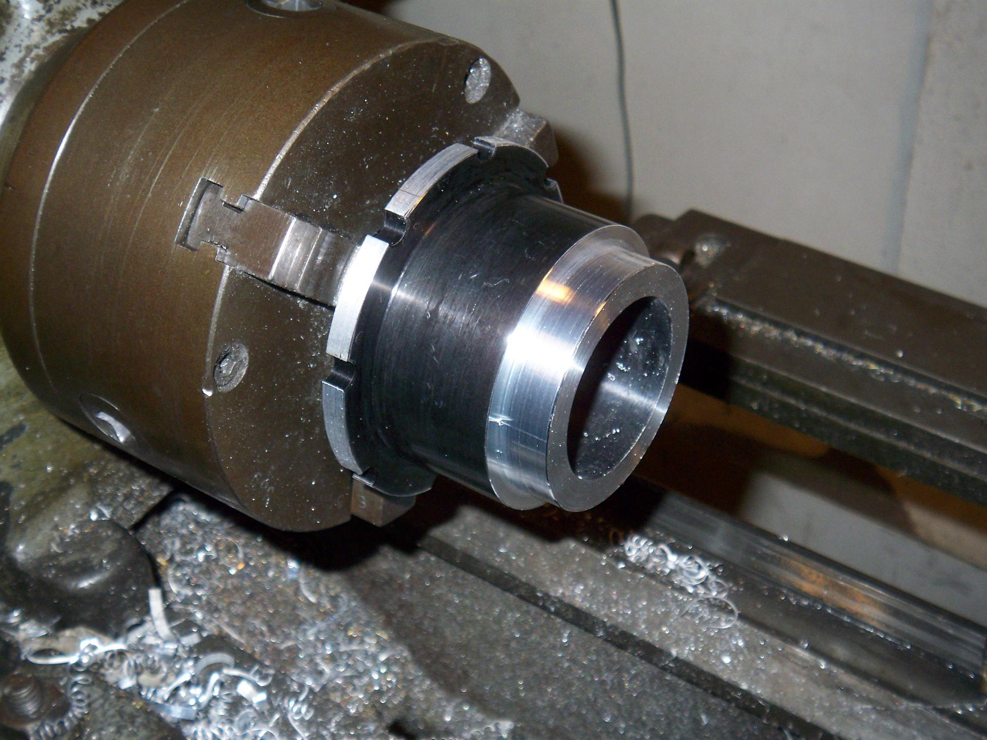
So that’s what I did. I turned the flange to 3.5″ to fit inside the wheel rim, cut the last two inches of the body off, then turned down a section to 60mmm.
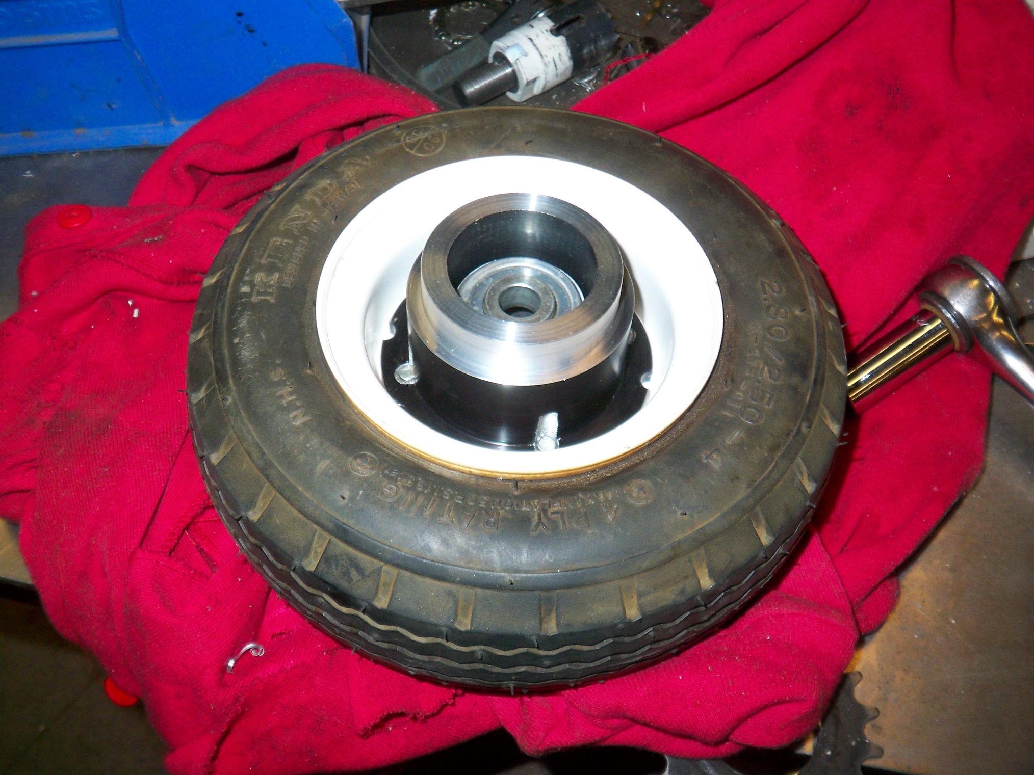
A pass on the mill for a wheel-matching bolt circle and the new Brake-O-Hubâ„¢ is done. Four 5/16″-24 (weird thread, because I had ’em already) screw into the aluminum hub to retain the wheel and its bearing tube. The Brake-O-Hubâ„¢ slips over this tube and extends past the wheel profile enough to stick into the brake bodies. A spacer will eventually keep the two apart the right distance while allowing me to slam the whole assembly together between a 1/2″ bolt and the steering knuckle.
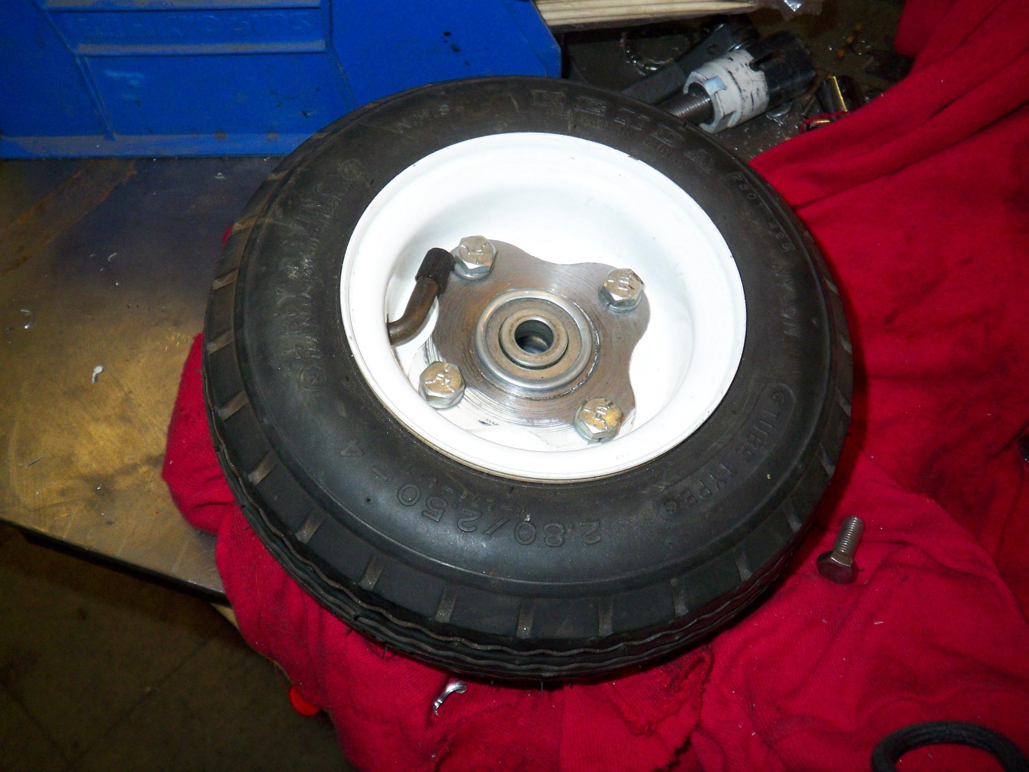
Other side. These wheels are similar to the cheapo handcart tires commonly sold at discount hardware places, like Harbor Freight. They have a stamped steel rim and a welded-and-stamped bearing hub tube thingie that is wider than the tire. Since I only needed one half of this tube, I cut the other half off and moved the bearing into the newly shortened hub.
No need for a 6″+ bolt cantilevered from the steering knuckle now.
I’ll be making one whole side of the drivetrain first, so I know what to do (or what not to do) for the other half. Things still unsorted include the actual steering linkage, how to securely mount the brake bodies (and how to actuate them), constructing the steering knuckle, and figuring out how to assemble everything.
And that’s just the front end.
Bot on?