Even though neither the omnidirectional 4WD vehicle nor the Roboscooter are my own projects, per se, I still feel like taking a bunch of pictures and writing about their development as Media Lab Sponsors Week approaches, especially since I’m pretty heavily involved in the R&D.
And of course I feel like showing off all the shiny toys. Here’s some stuff from today.
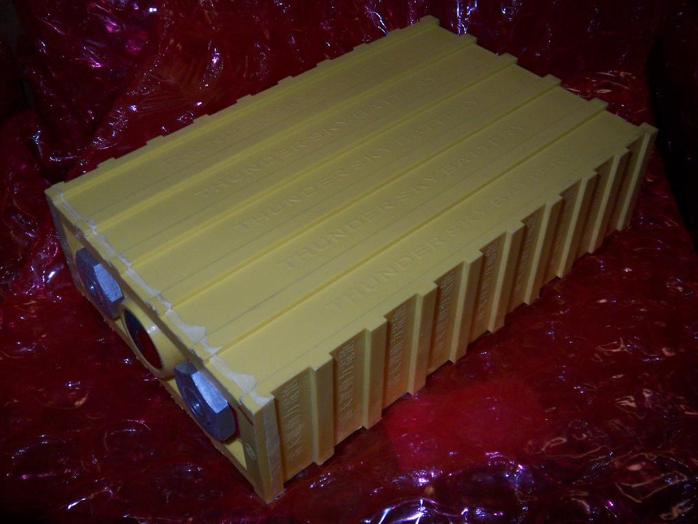
40AH large-scale rectangular LiFePO4 cells. Yes, this is one cell. It’s roughly the size of a construction brick, but a little flatter. 3.2 volts per cell. These are from Thunder Sky, which is a big enough name in the R/C hobby world to make me consider them legit.
The 4-wheeler will use one 48v(15S) pack for drive and one 24V (7S? 8S? 7.5S?!) pack for steering and the rest of the electrical system.
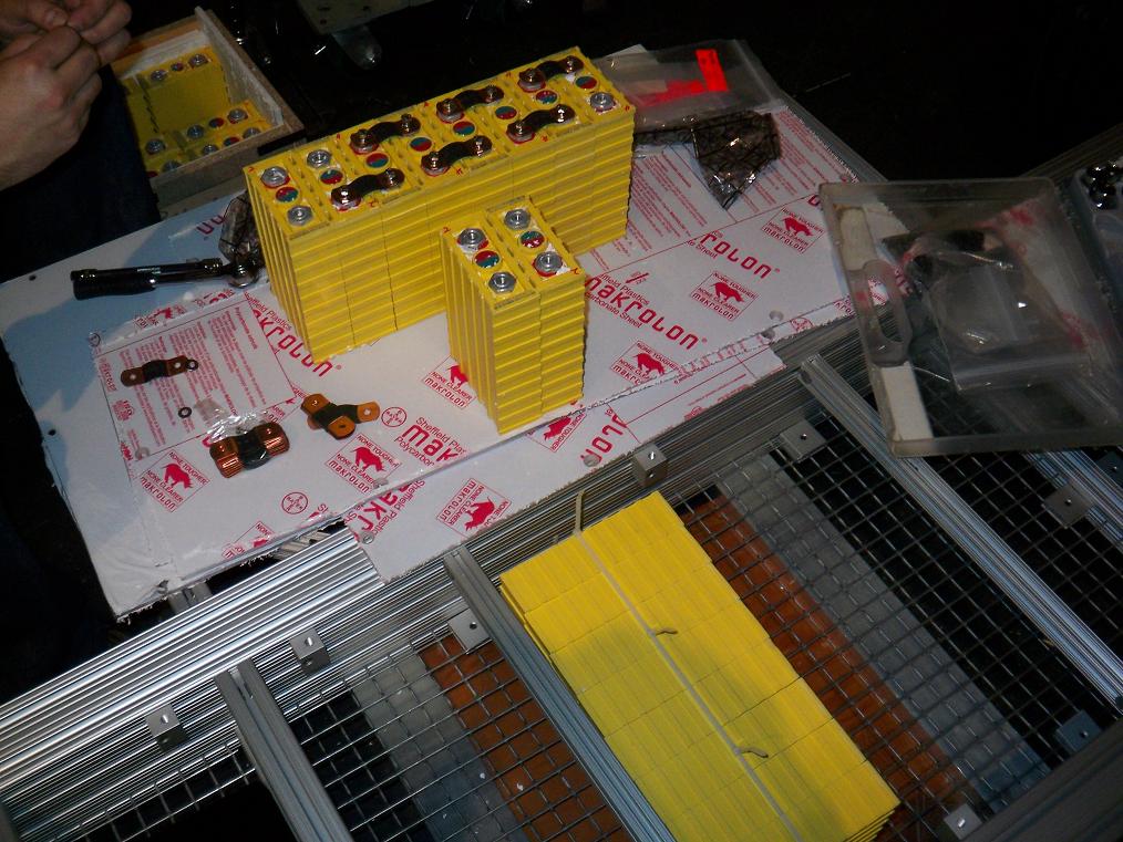
Packs under construction. The shipment of cells came with a bucket of formed copper battery bars that mounted to the terminals with screws. Handy, since nobody had to wield a kilowatt soldering iron.
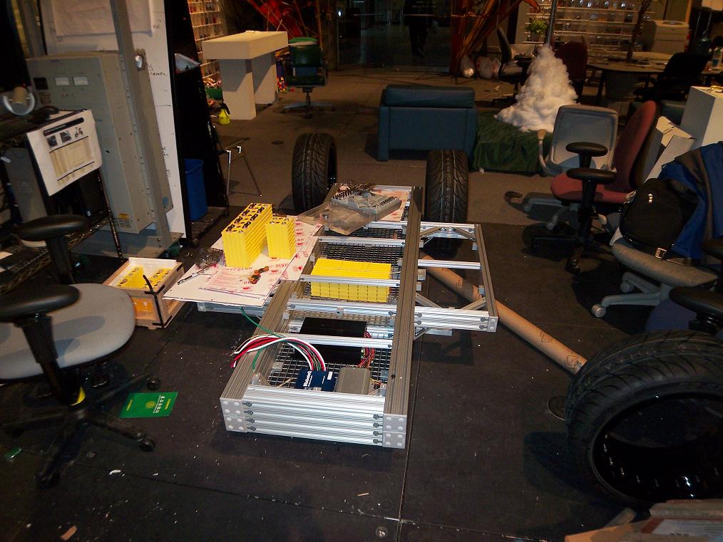
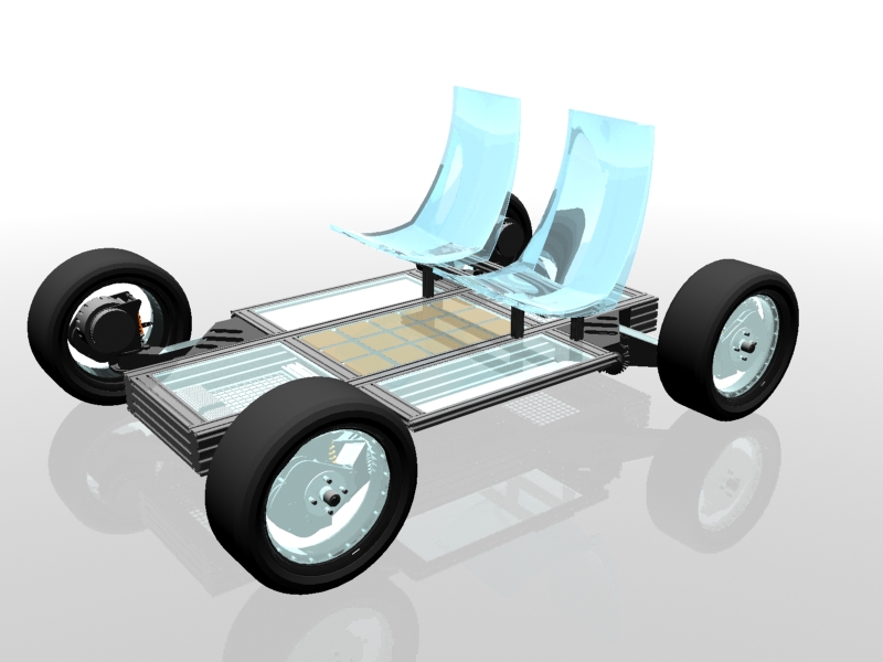
The chassis hasn’t changed much from last week, but that will not be the case soon.

Some waterjet-cut aluminum plate that will be eventually assembled into the steering arms and motor mounts. I love this method of construction and will probably be using it more in my own stuff – that is, 2D plates cut with slots and keys that assemble puzzle-like into a 3D shape, which is then retained by screws. With a 5-axis nozzle, I’m sure we could make even weirder shapes.
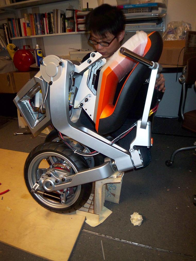
Here’s a shot of the (mostly) functional scooter in folded form. No, that’s not me fiddling with it.
When folded, the scooter is strangely aesthetic in a way, like someone in various yoga positions. It has a strangely organic yet still very mechanical look. But now I’m getting too artsy. The parking stand is only a mockup at the moment, as the above picture shows. A hardcøre metal stand will be made for the presentations.
There’s been both mechanical and electrical work on the thing done, since some parts weren’t made to spec or weren’t there at all (Hey, how much moving does it need to do at a show? None!). I’ve been working on a closed-loop controller for the folding process as well as doing some fabrication work.

Like this. This is the main seat folding control link. The 4-bar linkage which folds the seat in sync with the chassis was made with some links too long (I think it was a revision control issue). Fortunately, they were too long, becuase they could be shortened. The process was to slit each link, mill a bit off each end, then recombine them with a “connector block”. The links are C-channel in profile, so making this block was simple.
I also discovered that having the depth stop on the drill press work with your countersink is a wonderful thing. Those are the best countersunk holes I’ve made to date.
So, what on earth am I working on anyways? Well, sort of both projects at once. I’ve been rather general purpose, building whatever needs building, but focusing somewhat on the electronics. This is great, since I get the best of all the worlds involved, but get to work on a field which I don’t have as much experience in.
The whole of spring break will probably be filled with build pics, so stay tuned!

