So there’s now a week left to go before the robots have to be packed up and shipped out. Nuclear Kitten is awaiting express-mailed parts from Hobbyking, and I’m just going to play it by ear in the time that remains. And now with Clocker done, I’ve primarily shifted efforts to Cold Arbor. Arbor is actually most of the way ready to be reassembled. The grunge-machining, which has essentially been me making gearbox after gearbox, is finished. I now have to turn my attention to the front of the robot and appraise the condition of the brazed sheet metal assembly.
But first, pictures of gearbox after gearbox, because that’s apparently what I’m cut out to do in life.
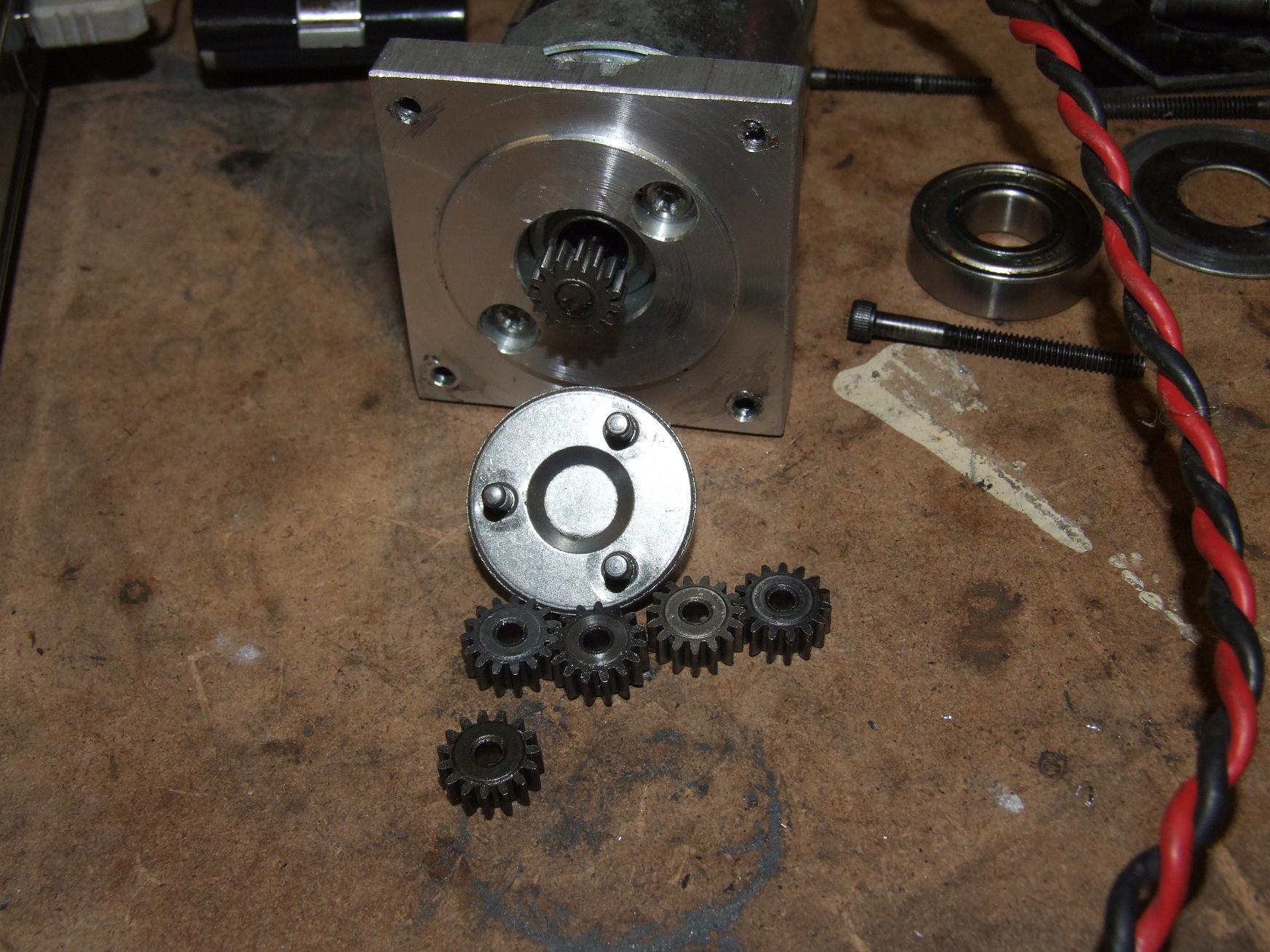
Cold Arbor’s right drive gearbox was cannibalized for Überclocker during Motorama 2010. Arbor uses the now exceedingly rare (and expensive for) cheap drill gearbox with 700 size motors, so replacement parts for the intermediate stage are hard to find. Clocker promptly ate the second stage carrier, leaving me with no parts left to fix Arbor.
Or so I thought – while rummaging through my drill parts box, I started hitting 15 tooth gears, one after another. I figured I cannot have so many 15 tooth gears and not at least one more carrier plate. If I could find another carrier, then I wouldn’t have to remanufacture Arbor’s drives, and the whole bot could be put back together in 10 minutes.
I found a carrier which was wider than the others. Since the 15 tooth first stage has a wider planetary engagement circle than the standard 36:1 drills with 18 tooth first stage planets, I thought I had found the mythical lost carrier. Too bad, it was just a wider 18 tooth carrier.
I was not happy.
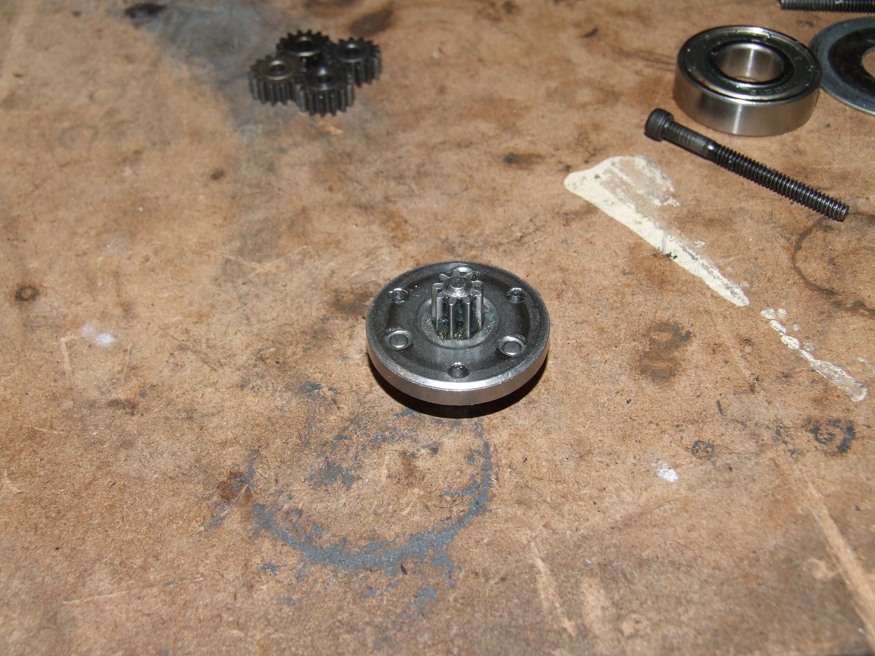
And I took my anger out on the carrier plate by… turning it into a 15 tooth carrier by drilling the damn pin circle into it. This was done on my haute usinage fixture, the rotary indexer.
Afterwards, I punched out the existing pins and moved them over into the new holes. This was actually a nontrivial exercise, since the pins were very small and demanded the straightest entry possible, something which I could not readily provide, even with a press.
After a bit of wiggling, the right gearbox is repaired. Why didn’t I just convert my carriers before?
I pumped the gearbox back full of grease, then threw it on the robot again. It will probably fail again during test driving, like everything else I build.
preduction

This is the junkyard parts-car equivalent of a Banebots P80 gearbox. Quite a long time ago, we bought one at the Media Lab to investigate planetary gearboxes for steering the embryonic Transformer that is the Citycar. It was experimentally determined that no, in fact, you cannot run a long Magmotor through this thing. And so it sat disassembled in a bag for the past few academic terms. Seasons passed and people graduated, and a few weeks ago I remembered that we had this thing and I needed a replacement for Deathrunner.
The motor pictured above is the Mini-EV-alike that I last remember seeing some time in 2007 before I left for the great northern wasteland. I guess I did end up bringing it with me. I literally have no numbers or performance data (or even a part number) on this motor, so I can only assume that it performs like a standard Mini EV. However, it’s a MEV with Magmotor-sized brushes, so it has to be more hardcore than the average MEV.
Regardless, I can’t have a 18-24,000 RPM motor feeding into the worm drive. So this is where the scrapped P80 comes in. I’m going to harvest one stage, the output shaft, and output carrier in order to make a 4:1 “preduction” gearbox for the motor.

There are three major machining steps in chopping and screwing the P80. The first is to cut down the ring gear so it’s sized for a single stage. It turns out that the ring gear is actually steel, and not brass or Shitluminum 9000™ that the smaller Banebots gearboxes are made of.
Next, I made the motor mounting plate using some 2.75″ diameter aluminum. The holes were processed on my indexer once more (which was conveniently zeroed in already from drilling the new drive carriers).
Finally, I bored out a spare 4:1 planet, which has the same number of teeth as the legitimate sun gear, to press on to the 6mm motor shaft. I used an “A” size drill bit, which had a nominal diameter of 0.234″, and just shoved it through the gear. Then I shoved the gear onto the motor with an arbor press.
Proper manufacturing of interference fits actually involves math and factors in material properties, thermal expansion coefficients, allowable stresses in the material, and some magic numbers. My method is to just shove with a bigger press.
The protruding motor shaft was ground down.
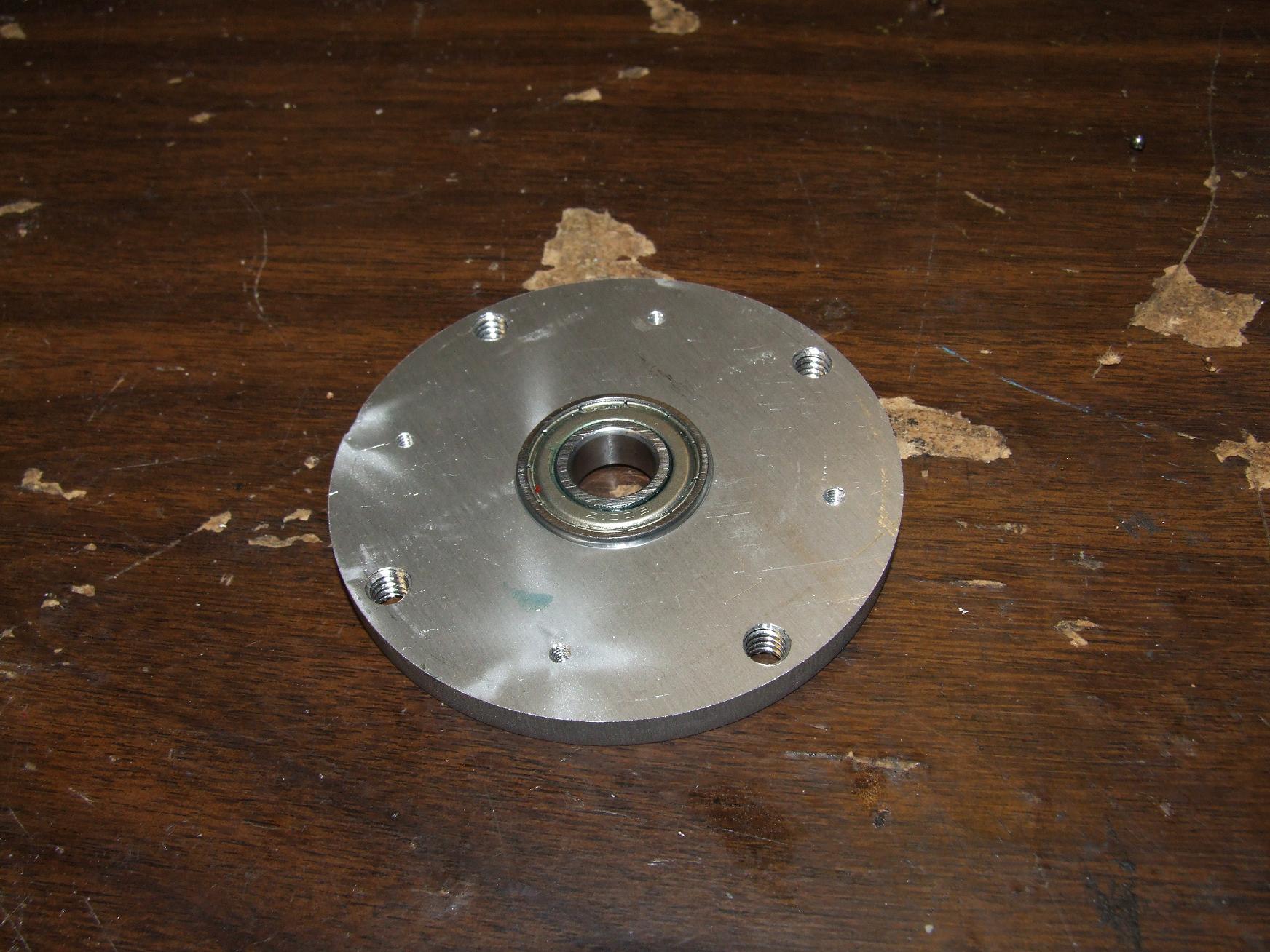
The front bearing carrier plate was a waterjetted protoform job. I originally specified double 6801 bearings, but I didn’t have any on hand and ordering some would take a week (or cost more than it should from McMaster). In lieu of double thin-section bearings, I elected to just hammer the 6001 medium-section bearing out of the stock P80 faceplate.
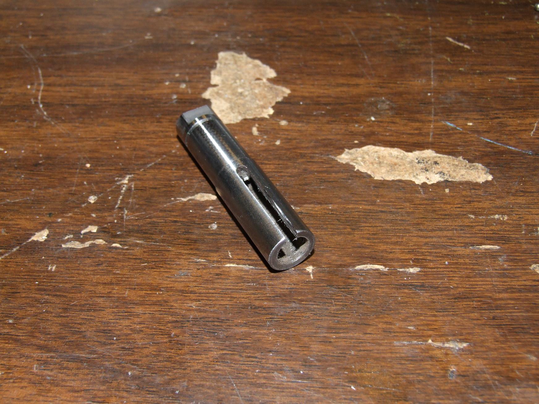
The P80 had a 1/2″ diameter shaft that I decided to take advantage of. I drilled the center of the shaft to 5/16″, enough to slip over the worm gear input. At that point, the bottom of the stock keyway in the shaft was a few hundredths of an inch away from breaking through to the internal bore, so I cut it out with a Dremel.
The result will be yet another clamp coupling, like Clocker’s former arm drive and my funky die holder. And Fankart!’s propellor mounts. I love these things too much.
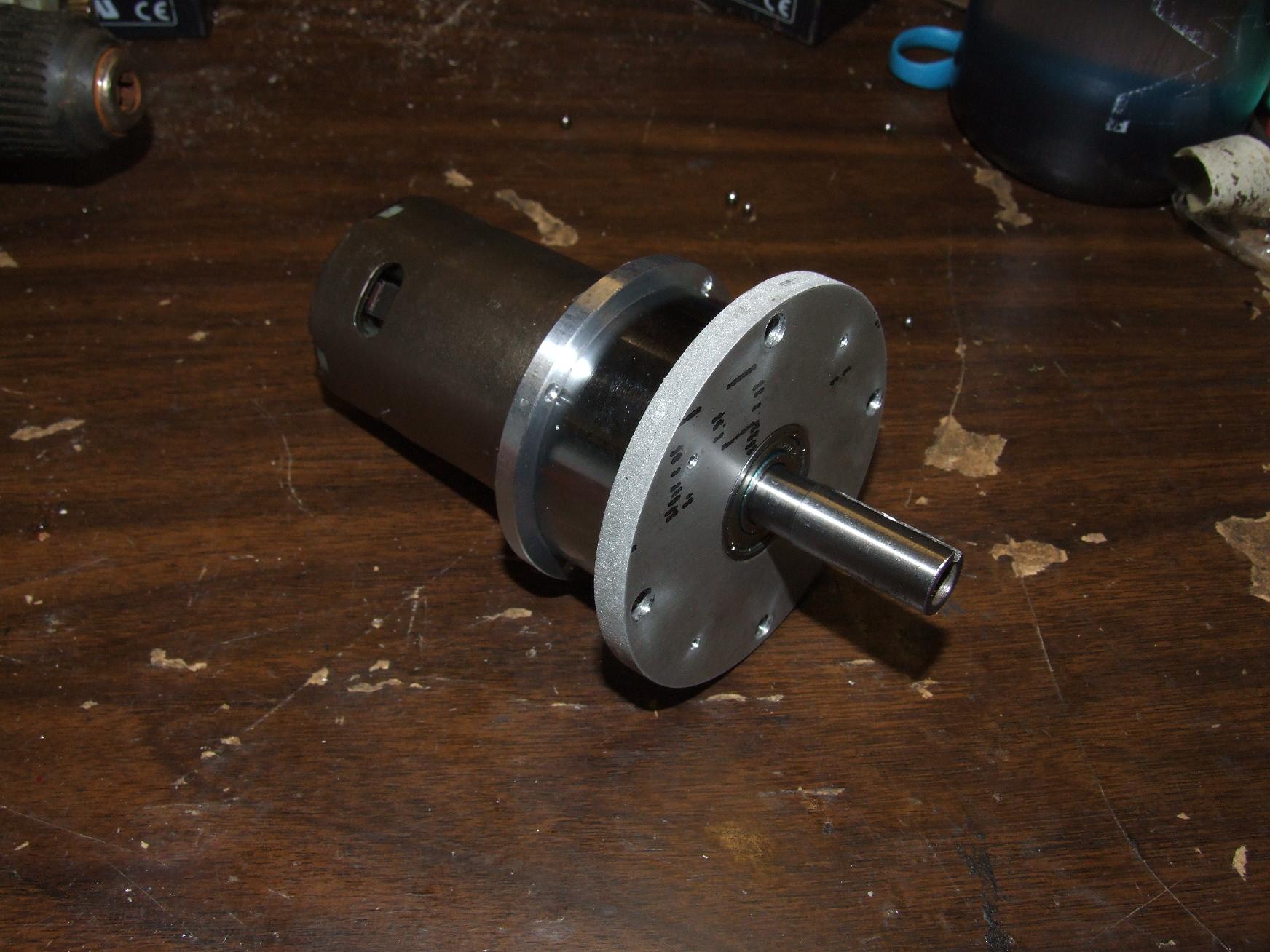
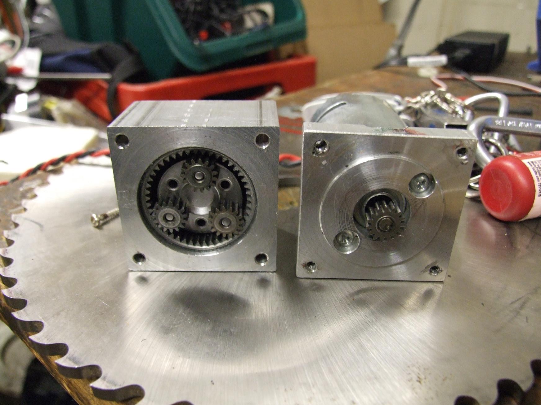
Here’s the Preduction drive, assembled but without hardware. I approve of how clean the whole assembly is.
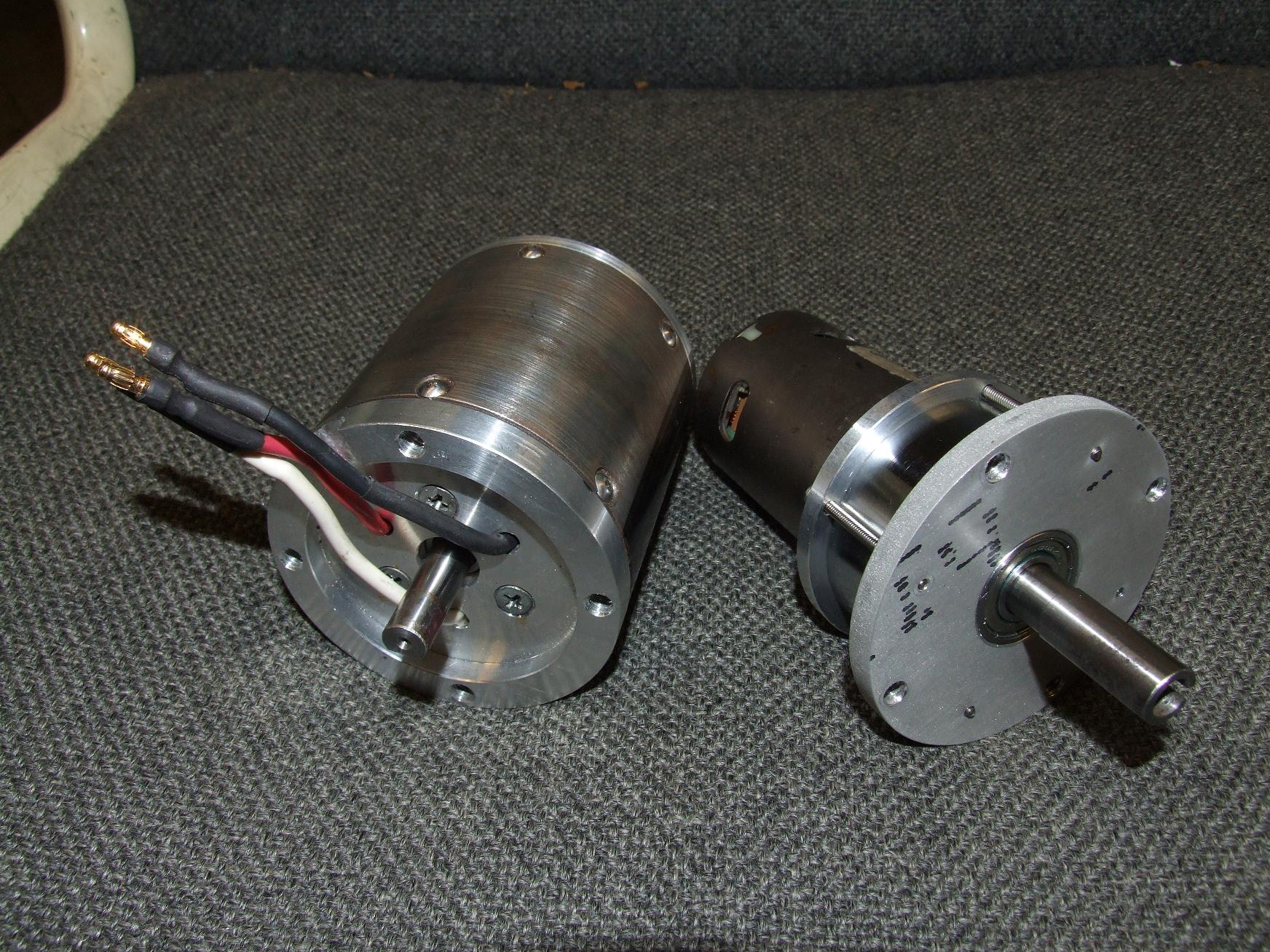
Compared to Deathrunner, Preduction drive is about 1/2″ longer and unfortunately not that much lighter.
framing the issue
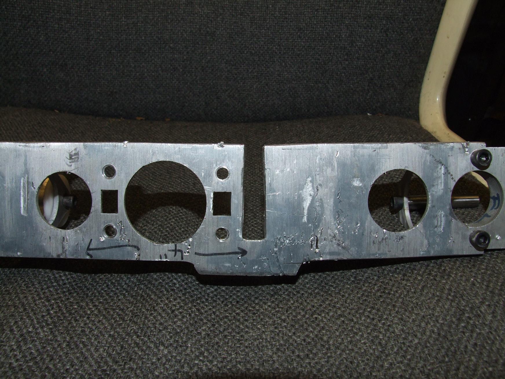
Here’s that “bent frame” issue that I described back during the first Cold Arbor situation sizing. Essentially, this part of the frame is the most highly stressed point in the entire robot because of the thin cross section and its location right next to the saw mount.
Yet it’s also really poorly designed. My tabbing and slotting didn’t reach all the way across the gap, as the fracture failure on the lower right portion of the dropdown tells.
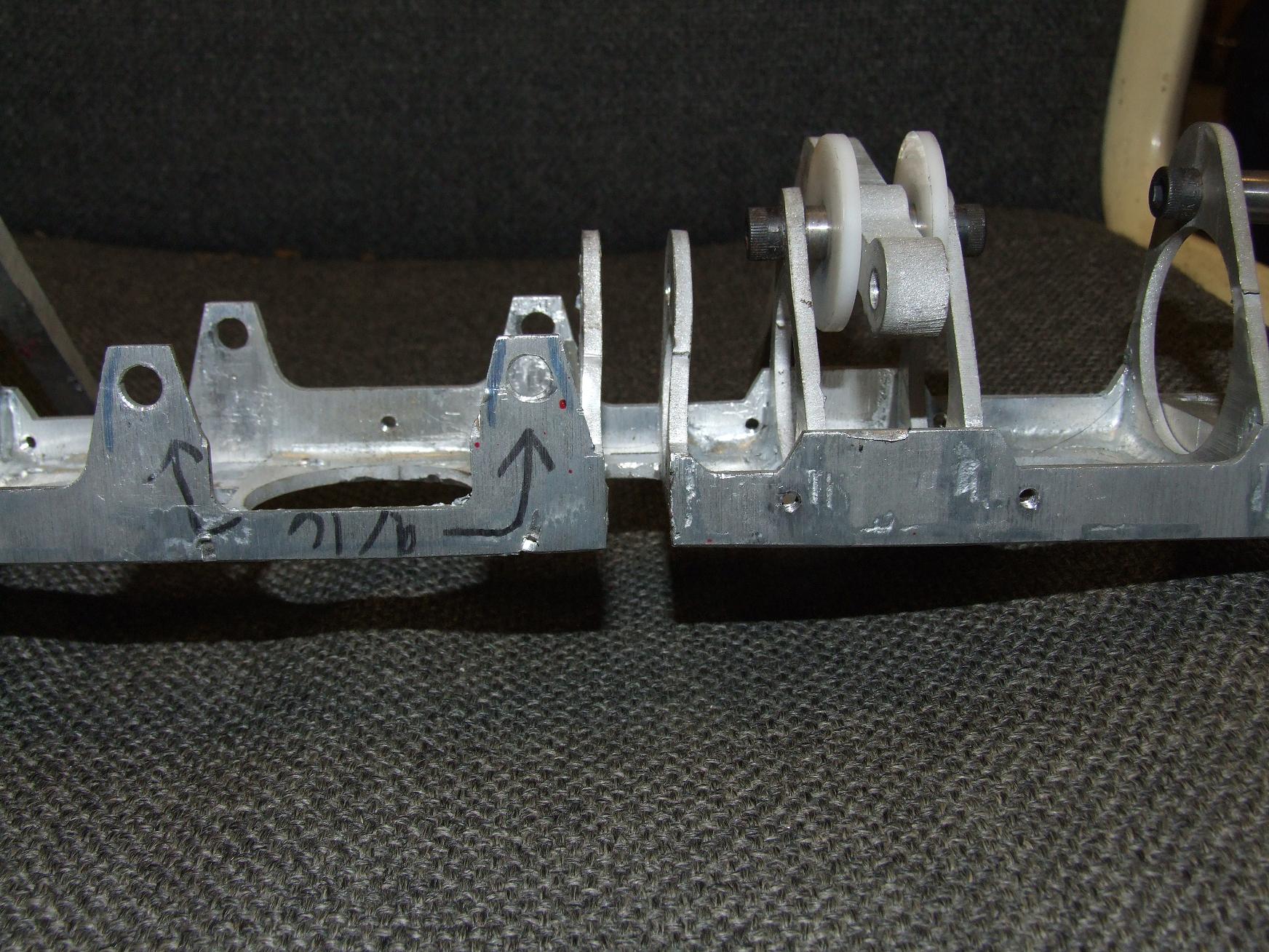
Additionally, where the saw connects on the other side, there’s huge weight-reduction holes. Thus, when this area inevitably experienced bending loads, the flanges just bent away.
Fail. I have a few front assembly cut out of 1/8″ aluminum that addresses both of these problems, so all I need to do is braze it together and throw every component back on.
Oh – there’s one more problem. The bottom fingers of each claw are attached using Impossible Standoffs – meaning standoffs which I threadlocked on both sides. Now, how the hell do I get those OUT?
heat is helpful in removing the stronger variants of threadlock
Like Andrew said, a moderate amount of heat will usually help with threadlock. I usually use a MAPP gas torch when I need to get rid of some red Loctite, and it’s always worked well.