With the balancing circuit prototype demonstrating consistent and non-glitchy angle indication, I’m picking up the slack on the mechanicals. Work continues with the frame being fully assembled, motors mounted, and the tilting handlebar essentially finished! I’m now just missing the handlebar tubes themselves and some big chunks of aluminum to carve the wheel hubs out of.
Things are on track for the Maiden Faceplant some time in early January. Meanwhile…
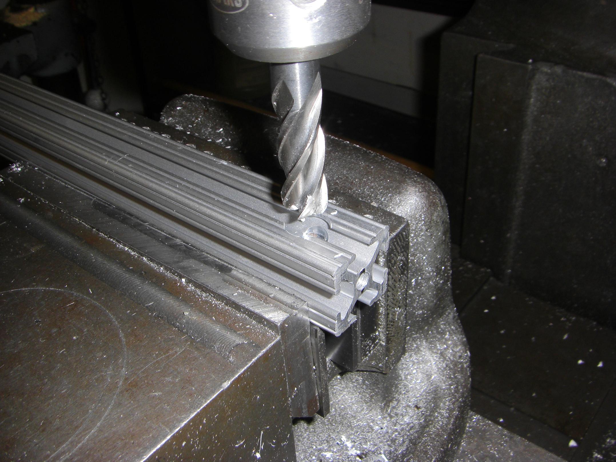
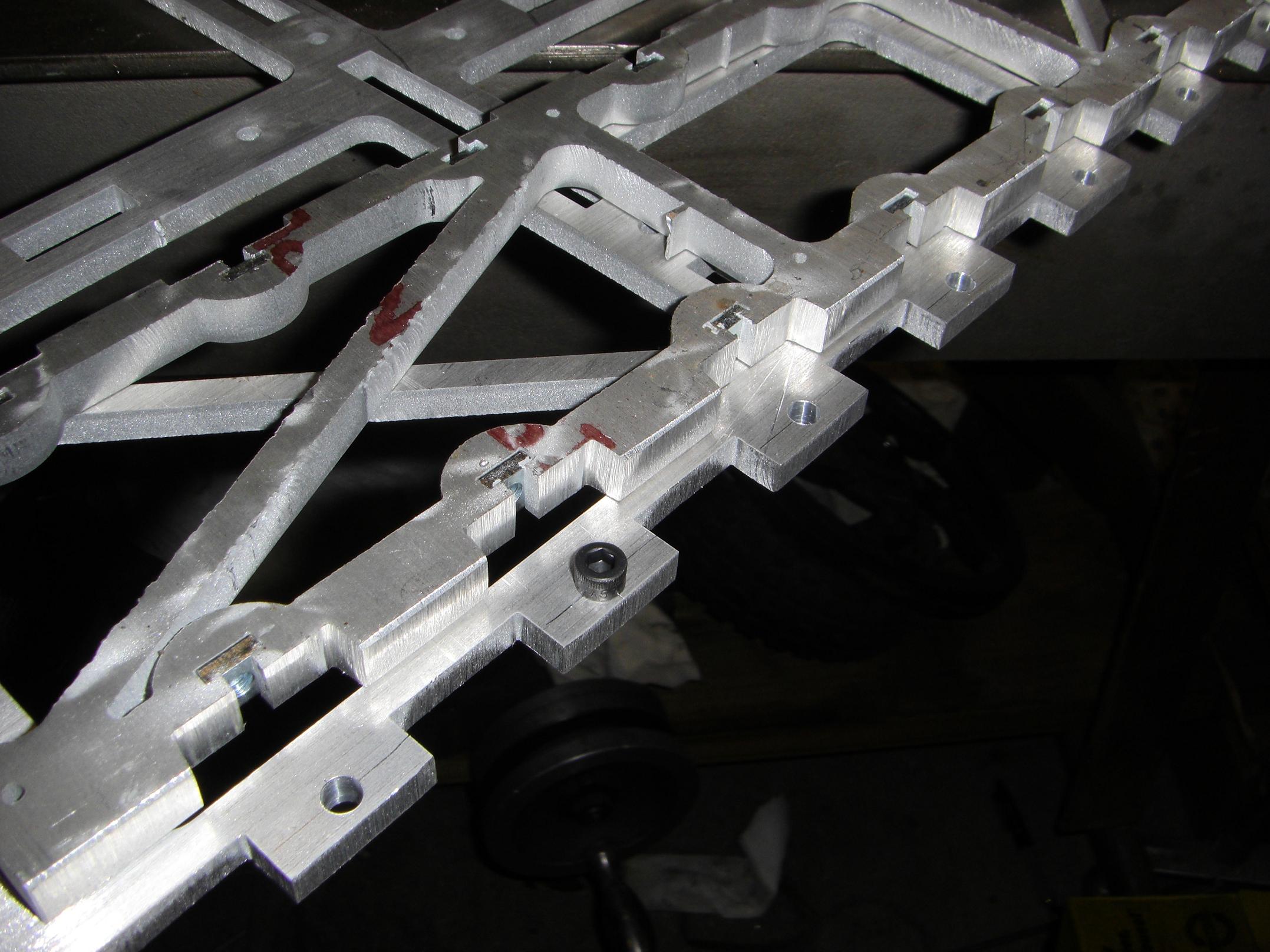 When you make fancy waterjet-cut puzzle frames, you shouldn’t forget, like me, to lay out the fastener holes that will put them together.
In this case, I accidentally the front and rear structural screw holes. So it was back to the old center punch and caliscribing, followed by some quick drill press work. Manual fabrication… can you imagine that?
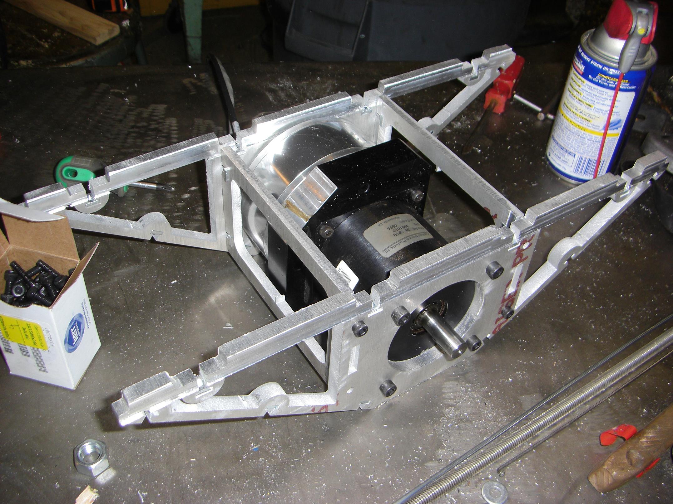
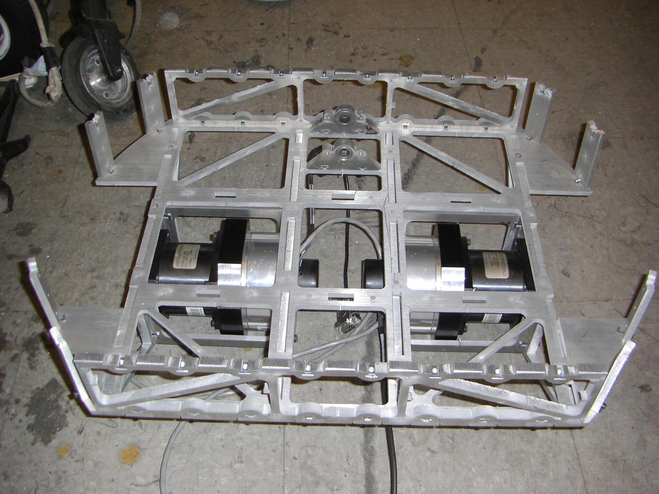
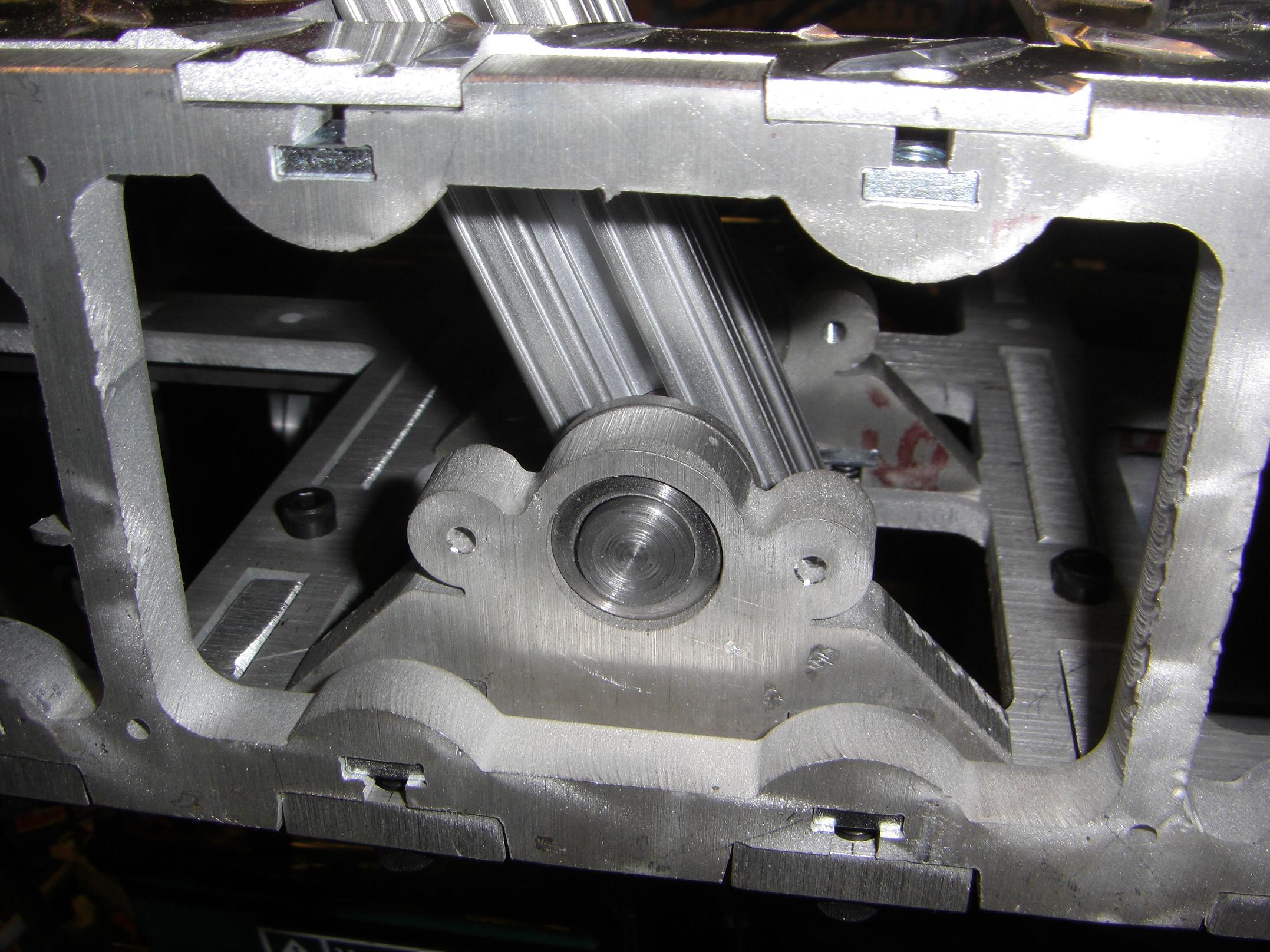
While I had the temporarily-fastened frame taken back apart to drill the new baseplate holes, I decided to fill the empty motor cages with motors. The KOOOOOOLmorgen motors are sandwiched between the two rails, mounted on both ends for maximum load carrying ability. I need high stiffness in the motor mounts because of the single-supported axles.
Rinse and repeat for both motors. After adding the requisite hardware, I should not have to fiddle with the bottom structure ever again. At least, until something breaks.
In this image, the “pillow blocks” for the tilting handlebar are already mounted in place. Said handlebar assembly will pivot at this location a few degrees to either side, and the rotation will be read by a potentiometer and translated into a differential motor speed to let the vehicle turn.
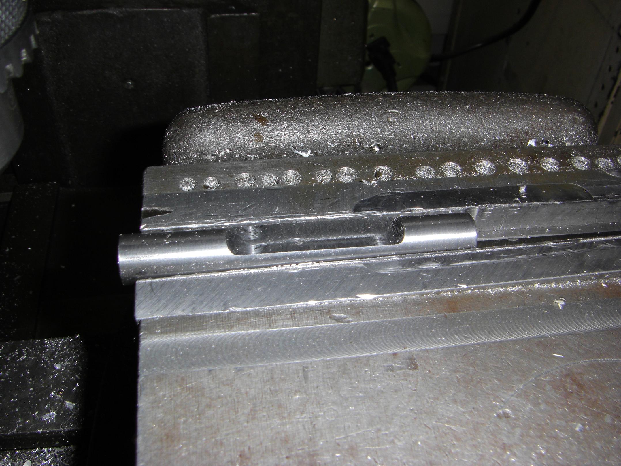
The pivot pin is a 1/2″ steel rod with a milled flat to position the handlebar and an axial center hole to couple to the feedback pot.
By pure chance, I managed to select a piece of 1/2″ alloy or tool steel. What a total bitch to machine – I had to break out the carbide to mash through it- but the shaft took on an almost polished appearance after a run through with 1000 grit sandpaper. I guess that’s why they grind tools instead of mill them?
The complement to the above is a single 40″ stick of 80/20 structural extrusion, the 1″ flavor. Conveniently enough, the extrusion has a center hole that is the correct diameter to be tapped 1/4″-20. This meant I had a set screw attachment solution practically ready to go.
To interface this with the pivot pin, I just crammed a 1/2″ cutter through the extrusion from one side to the other.

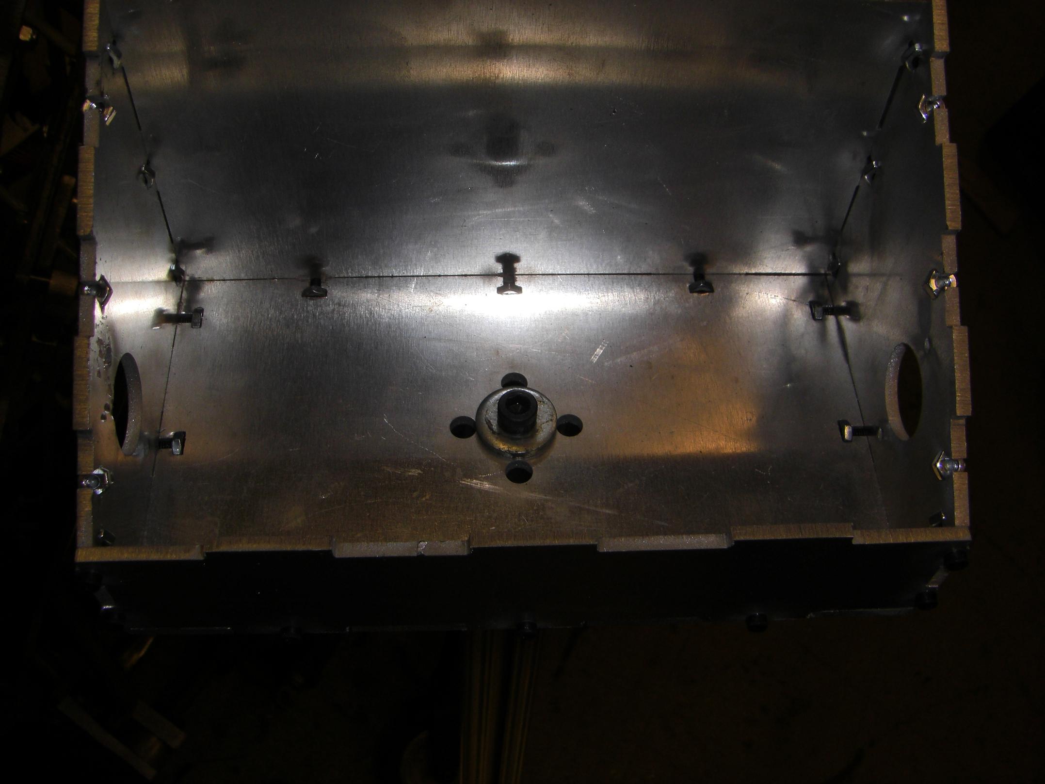
A view inside. Visible are the pivot pin (kinda…), its +2 Set Screw Holes of Potentiometer Retaining, the 80/20 handle stick, and some spacers. A big cap screw is cranked down the center hole to lock the pieces together.
Another view of the assembly. I need to come up with a way to spring load the stick such that it tends to center itself. I actually couldn’t scrounge either 1) two matching springs or 2) stiff enough springs or 3) springs of a workable physical dimension, so a hardware store run will be made in the near future.
Without the centering, I’d have a hell of a time actually trying to operate the thing.
On the other end of the handle stick is the control box. It’s retained by a single cap screw, threaded into the 80/20 center hole. This isn’t particularly structural, but… it doesn’t need to be. Right?
The control box will never have to support the full vehicle weight, or any number over, right?
Right? :(
Oh, the 4 perimeter holes don’t serve a mechanical purpose – they are only there to pass wires through. They are at the same distance from the center as the cavities in the 80/20 X profile, to encourage clean wiring.
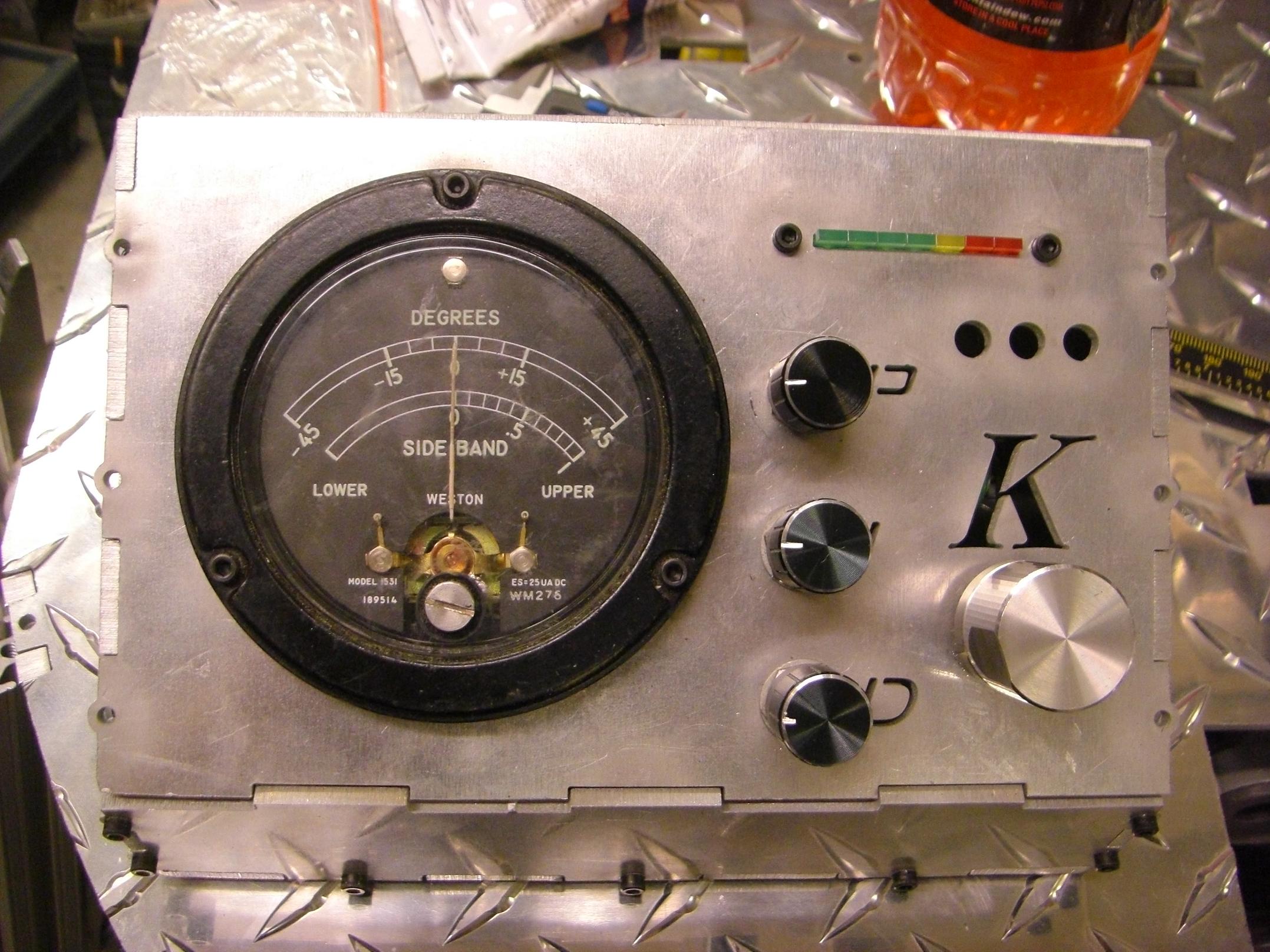
Speaking of the control box… I finally got my SHINY ALUMINUM KNOBS from my most recent favorite Sketchy-ass Ebay Electronics Dealer (SEED). I purchased a grand total of 20. They’ll be useful for future knobbery, but Segfault only needs 3. The other Big Knob was scrounged. Besides the knobs, the same order brought in a handful of multiturn trim potentiometers and a stack of single-sided protoboard.
So the user interface is now complete, with exception of the power switch. Can you find the power switch? I can’t either right now, because it doesn’t exist, but the ultimate goal is to hide it in the most obscure location possible, characteristic of older electronics equipment (designed by engineers rather than product designers, I imagine). For instance, all the MITERS oscilloscopes have their power switches integrated as a small selectable section of the scale illumination & beam intensity knob, hidden amongst the other knobs.
Here I am trying to think of some dastardly way to make the zero adjustment screw on the degree-o-meter the main power switch.
Okay, enough is enough – here’s where SEGFAULT stands (LOL PUN) as of today.
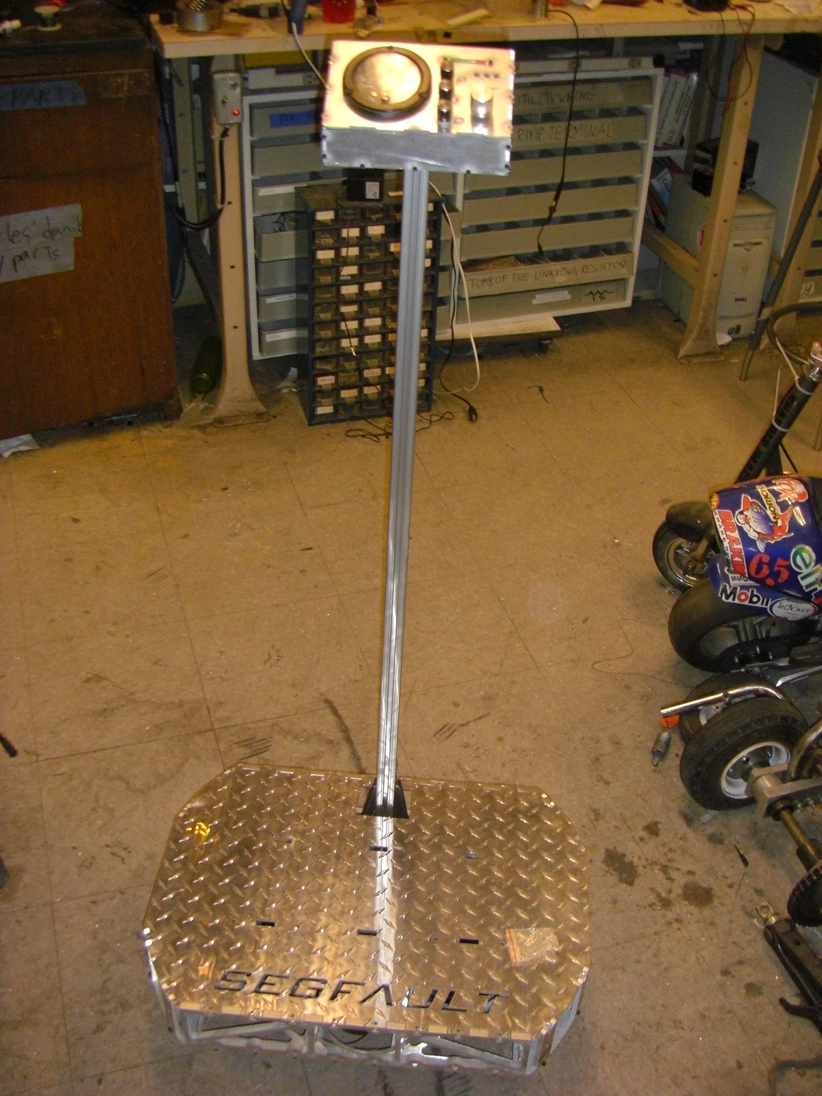
Missing: things which herd electrons, wheels, and handlebars. And cool glowy lights.
I’ll be making the wheel hubs soon, hopefully out of one of my “stock” hugeluminum billets. The handlebars are easy – they can be just about any steel or aluminum tube. I should at least be able to stand on this thing and practice static balancing soon. Then it’s back to the electronics!
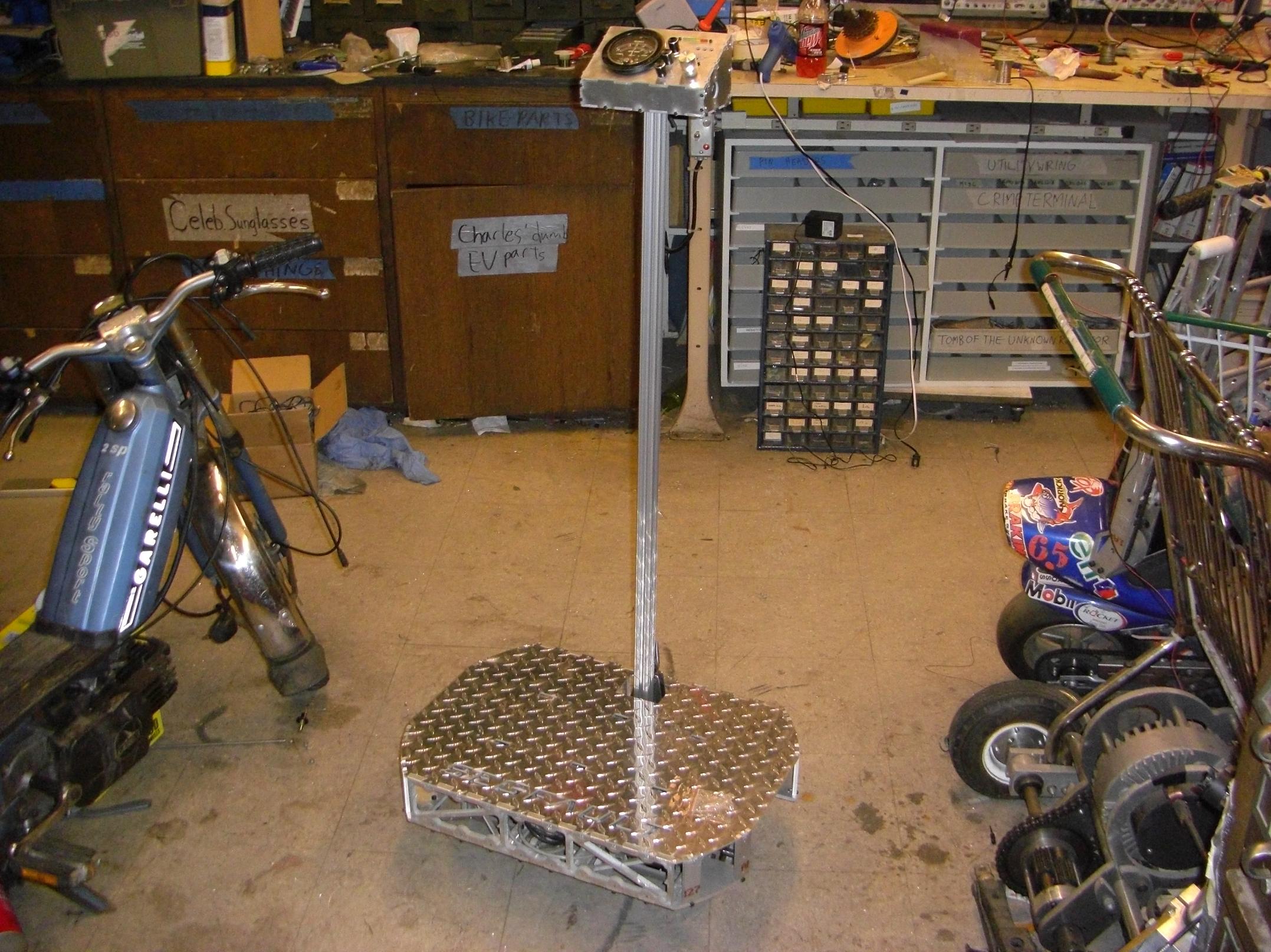
Here’s a “global perspective” picture showing the proportions of SEGFAULT in relation to other things in MITERS. It’s a good 4 feet tall without wheels. The handlebar position will be higher than real Segways, if nothing else but to lessen the sensation of standing on a pogo stick.
MORE TO COME!
HOLY CRAP THAT’S AN AWESOME GAUGE. its so appropriate
you sir are a badass, i tip my hat
THIS LOOKS GLORIOUS