It all started in 6.131.
What caught my eye in the description was “go-kart controller”. I registered for the class back when I blew up a new LOLrioKart controller about once every month or so. I wanted to learn how to do it right. Lingering in the back of my mind was the little mention of 3 phase AC inverters, but I was reassured by classmates that it was just V/Hz control for an induction motor, i.e. not really that exciting. A legitimate control method it may be, but it wasn’t BLDC .
It all changed, though, when I received the assignment handout for the AC motor control. Here’s a link to a paper jointly written by the course professor along with associates, which details the apparati and methods used in the class. Pay particularly close attention to Figure 15.
 So what does it do?
Space Vector Modulation
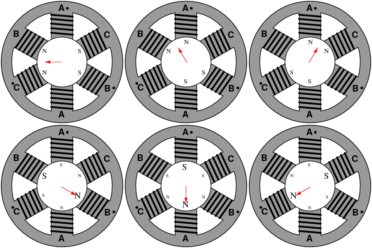
SVM is a control algorithm for generating 3 phase waveforms to drive motors. It is based off the simplest possible 3 phase AC motor, that which has 1 winding per phase and 1 pole pair (that is, 1 N and 1 S on the rotor). Such a motor has six states it can be in which are represented by 6 voltage vectors.
There are actually 8 total states, because if the three phase legs are taken to be either on (connected to V+) or off (grounded) and treated as binary digits, there exists all combinations of 0 and 1 from 000 to 111. Both 000 and 111 themselves produce no voltage across the motor, thus no movement, and are invalid states – observing the diagram on Wikipedoia, this corresponds to all the top switches or all the bottom switches being closed.
It is interesting to note that at no time are the top and bottom switches in a leg closed together. This would result in everything blowing up because the power supply is being shorted.
What this distills down to is that simple motor commutation can be achieved using a finite state machine model. A device with six (or 8, counting the zero vectors) states that steps through them in order will commutate an AC motor.
The class circuit provides this FSM functionality in the 74LS138 3-to-8 Multiplexer chip. In its legitimate life, it helped select peripherals for microcontrollers. Here, it takes the conveniently three-bit input and translates that to one output.
So that means if you put in a binary number valued 0 to 7 (000 to 111), you get one output Y0 to Y7 selected.
Now all that’s left to do is associate each output with the top and bottom switches. Observe in Figure 15 above how the OR (actually NOR, because the 74138 is an active-low chip) gates are each tied to two 74138 outputs. That means each output NOR gate is on for two sequential states, which follows the SVM rule of at least two switches, one top and one bottom, always being on.
So how does that correspond to the 3 phase bridge circuit? Let’s start at “state 1”. Motors are round objects, and to a degree you can fiddle with what’s called state 1. In state 1, Q1 is on. That means Q2 cannot be on, or things would smoke. So state 1 is Q1 and Q4 on, and the motor current goes in-1-out-4.
State 2 advances the motor to in-1-out-6, state 3 now toggles q1 off and turns q3 on, and so on.
- in-1-out-4
- in-1-out-6
- in-3-out-6
- in-3-out-2
- in-5-out-2
- in-5-out-4
- And the beat goes on.
The top and bottom switches are complementary and offset. The result in a motor is something trippy like this.
In the class circuit, the state switching is provided by the 74LS163, a 4-bit counter. In the lab assignment, we input a variable frequency square wave into the 74163, which sequentially stepped through its outputs from 000 to 101, 6 total states, then automatically resetting itself to 000 on state 5.
It is important to note that 000 and 111 here do not correspond to SVM states 000 through 111. The SVM 3 bit code is a Gray Code (of sorts), while the 74163 counts in raw binary. What the count from 000 to 101 does is select outputs 0 through 5 sequentially on the 74138. These output pins, in turn, go to the NOR gates and become commutation commands.
This was used as a crude VFD to turn an AC induction motor. The state machine sets up a rotating magnetic field in the motor, and it turns.
Oooh, shiny.
Face Vector Modulation
I wanted more.
I immediately saw how the simple SVM kernel could be used to run a brushless DC motor. Your average brushless DC motor has 3 Hall Effect magnetic sensors that pop high and low depending on the position of the magnetic rotor.
Wait, 3 bits?
This could get exciting.


