This is technically the sixth update of the bot overall, but only the second one in which I’ve actually built anything worthwhile, so it’s okay, right?
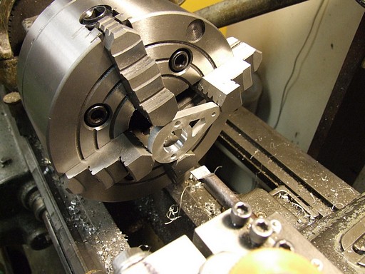
Look! It’s a bitch chuck!
Also known as a 4-jaw chuck, but I call it the Bitch Chuck since it’s a total bitch to use. It was determined that we could afford to spend some club money on replacing sketchy equipment, so I hopped on eBay and lassoed in some new 6 inch chucks, in 3 and 4 jaw form.
In testing and installing the new chucks, I discovered that the machine does indeed have a collet mode. My next step in shopbuilding is to get a wider variety of 5C collets.
The cool thing about Bitch Chucks is the ability to use the 4 jaws as the axes of your own coordinate system. This means you can, with enough jiggling of a dial indicator, center just about anything. It’s most often used for machining round features in substantially non-round objects.
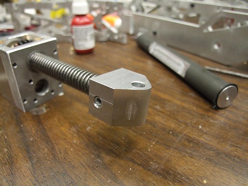
Such as my leadscrew actuator anchors, above.
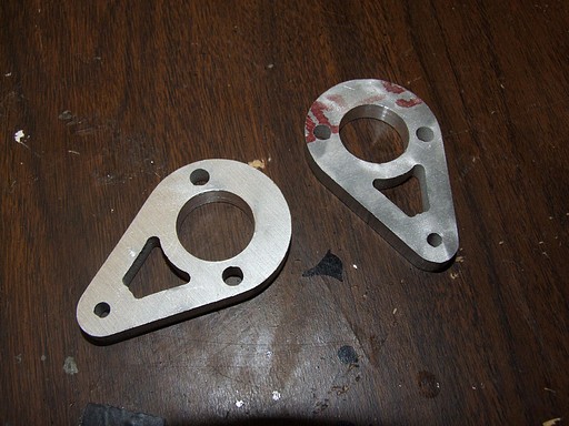
Bored out pieces. These were waterjet-cut first, which leaves a rather raggedy bore, necessitating secondary operations.
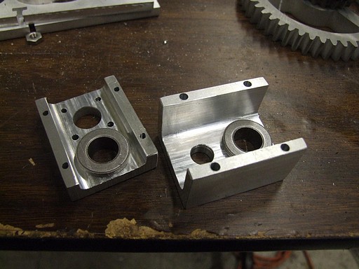
More actuator parts. The piece on the left was also waterjetted, then secondarily operated upon. The part on the right was milled from a block of aluminum.
These two pieces bolt together and trap an Acme-threaded nut between them. When the nut is spun, the whole assembly travels up and down a leadscrew.
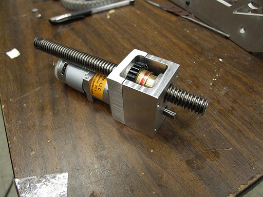
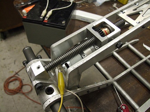
Pretend-o-actuator. A 28mm Banebots gearmotor (I’M SORRY IT WAS THE ONLY THING THAT WOULD FIT THE DESIGN) drives the leadscrew nut through a 1.5:1 additional reduction.
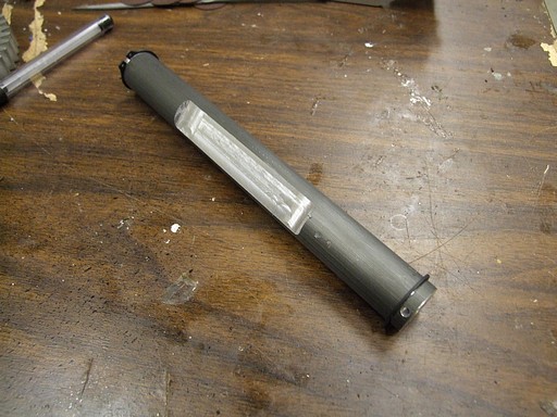
Fr0k main shaft, made of hard-anodized 6061 rod. The flat is for the fr0k hub to grip onto using a line of Giant Set Screws. It is otherwise smooth for the clutch connection with the fr0k gear.
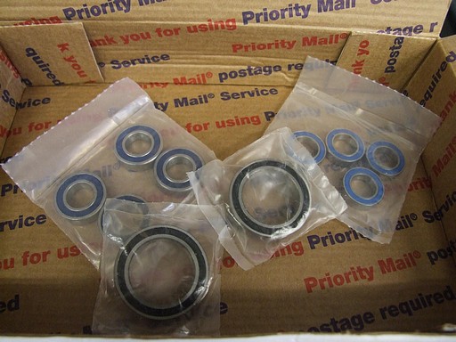
BEARINGS!
All the important bits (gearbox outputs) on Überclocker will be ball-bearing supported. Ball bearings, especially small and metric ones, are not cheap. That said, I got these from VXB, which…hey, sells cheap, small, metric bearings.
They are of dubious origin, devoid of manufacturer labels. But everyone knows that renowned ball bearing manufacturers have cool 3-letter company names, so they must be totally legit, right?
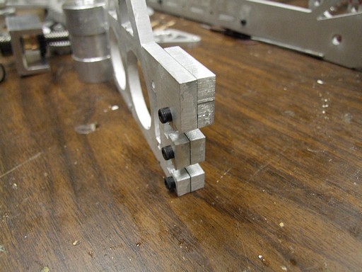
When I need a thick section of material to fasten a larger T-nut, but the rest of the part is thinner plate, it’s handy to use a screwed-in thickness buffer. Here are two quarter inch plates combined to make a single half-inch fastening location.
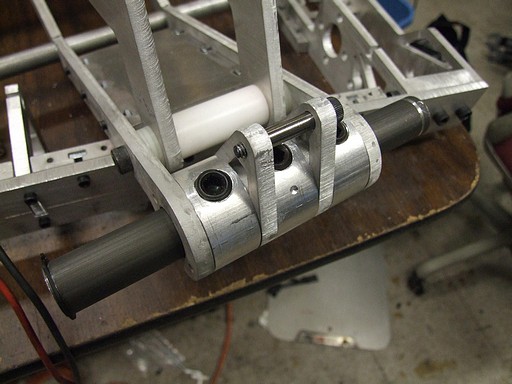
Mockup of the fr0kshaft. The three aluminum donuts with Giant Set Screws are the fr0k shaft hubs. A long shoulder bolt passes through a two-hole pattern in the side (barely visible). The left fr0k tine is a clearance, the right one a tapped hole. The entire assembly binds together, then is Giant Set Screwed down.
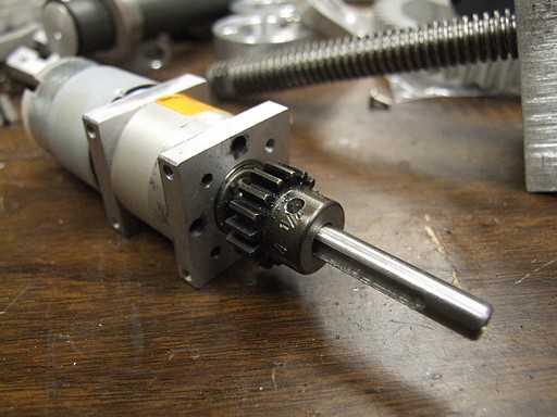
Alright, back to the upper fr0k actuator. The motor pinion bore is 5/16″ and the motor shaft is 6mm. That’s a space too wide for even the thickest Loctites to bridge.
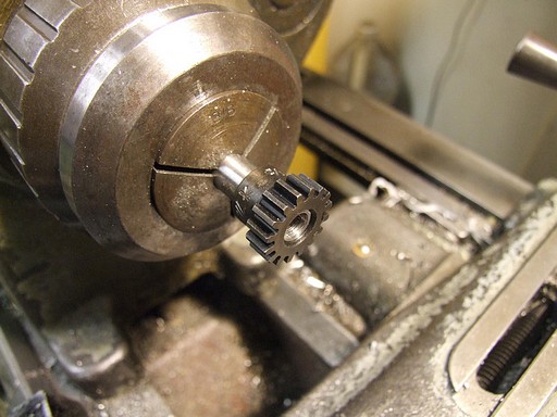
So a spacer is warranted. Here, I turned down a random steel rod to press fit into the gear’s stock bore. Then I pushed the gear onto the future spacer by locking down the tailstock and using the quill to apply a force to the gear.
Yeah, that’s right, I used a metal lathe as an arbor press. I hope the shop instructors aren’t reading this.
Drilled, tapped, and mounted. Conveniently enough, the Banebots motor has a keyway in the shaft which seats a #6 set screw very well.
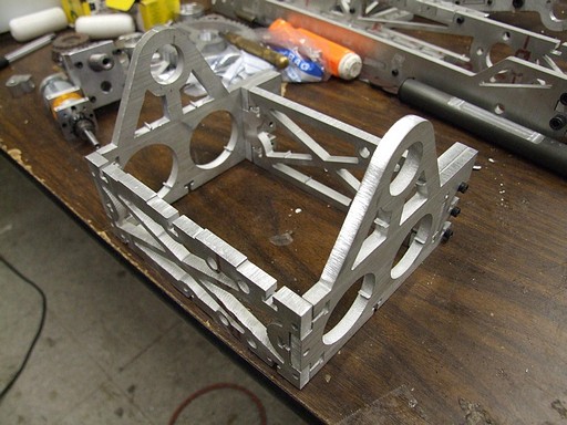
Here’s the fr0k base in mockup configuration. Eventually, the Integrated Dual Frakenb0xen will go in the middle, secured by the four mounting holes.
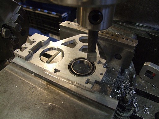
Secondary operations on the fr0k base parts. I center-found one hole, then referenced the rest from there. This is to avoid Waterjet Weirdness creeping too much into the parts. If I had centered and bored each hole individually, they would be in 3 different incorrect places. At least with the former method, they may all be off by a hair, but it’ll be in the same direction, so things still go together.
These ring bearings will support the hubs of the Frakenb0xen pinions.
Leadscrew anchor block. This was originally going to be a waterjetted-then-machined part, but I found the most conveniently placed block of 1″ x 1.5″ x .75″ aluminum ever, so I just fabbed it in a few minutes.
The radius was smoothed on the belt sander after I made 3 45-degree angle cuts to approximate it.
This anchor looks kind of like the previous one which failed miserably, but is actually much improved because the set screws reside in deep-cut flats on the leadscrew. I would have to shear the set screws, strip the leadscrew, or just plain rip the leadscrew anchor ears right out of the fr0k assembly.
i.e. It takes alot more force to fail, but will fail irrepairably and probably inopportunely.
Great.
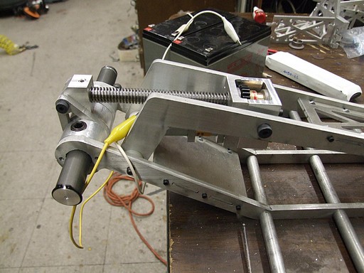
Testing the actuator! The banebots motor is _fast_. Ridiculously fast. The arm hits physical travel limits within maybe one second. This is so fast that I think I should have picked a finer leadscrew or something.
Or it could arise from the fact that I’ m triple-overvolting the BB motor, meaning it will also not last very long. This is one candidate for a high voltage motor swap. Regardless, it will need a limit switch or sensing element of some sort, because in the heat of battle I’m probably going to just jam on the throttle stick with reckless abandon.
The upper fr0k in its lowest position can actually hit the ground below the bot. I’m not sure if this is a good or bad thing yet. Again, an argument for travel limiters.
The whole arrangement sort of reminds me of cantilever-style C-clamps.
HEY!
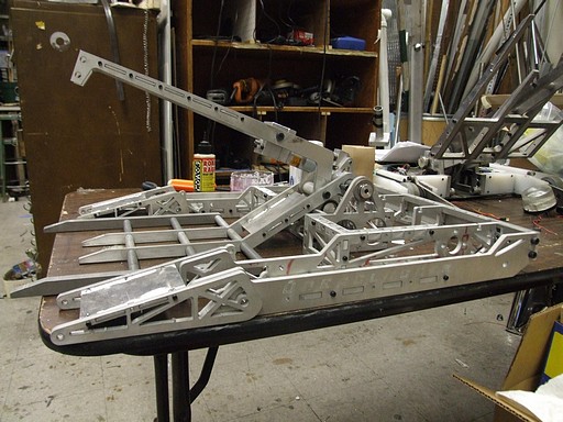
It’s time for an episode of PRETEND-O-BOT! In this episode, Charles wonders where the fuck all of summer has gone and why only 3 weeks remain before tools have to be down.
The fr0k in its maximum opening position can grab objects roughly 10 inches tall. This is good enough – few robots are entirely that large. If I wanted to, I could cut out a portion of the truss that binds the top fr0k sides together and get another inch or so of rise. However, then I start risking running the motor into things.
- Make the drive gearboxen and hubs, including
- Cut out the drive gears
- Make the Integrated Dual Frankenb0xen
- Finish the leadscrew actuator
- Design the electronics enclosure
- Make the electronics enclosure
- Design the top and bottom plates
- …make the top and bottom plates
- Panic
- Panic
- Panic
- Panic
- Panic
- Panic
- Panic
- Panic
- Panic
- Panic
- Panic
