Poor Chibico….oh, hold on, it hasn’t quite gotten there yet. That should come in a few days after I crash and rebuild it like 10 times!
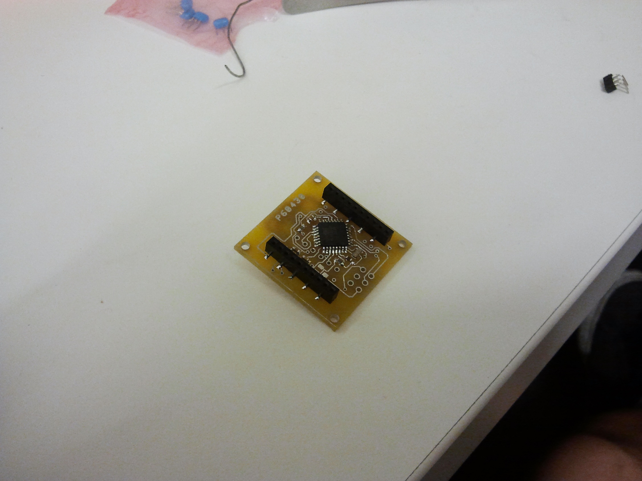
After the previous expository update, I finished designing the central carrier board for the ESCs, XBee, and IMU module. It’s easily the smallest and densest thing I’ve had the joy of routing:

Doesn’t look that small, right? That’s because the whole thing is at like 5x magnification. The outer dimension is 1.25″ square, and the mounting holes are on a 1.1″ square. What also made it difficult was the fact that the components weren’t all in a neat line like my motor controllers usually ended up being, but rotationally distributed, necessitating (relatively) long wire traces.
Also, remember how I said I would never, ever use SMT components smaller than 1206? Well…. uhhh… I still never will, but I had to use 0603s on this one because 1206 parts are so damned huge.
Notice that the IMU and ESC connections imply that they are vertical. Well, they are going to have to be – I spent a long time trying to cram four of those controllers, the IMU, the XBee headers, the ATMega chip, and all the random little passives into a 1.25″ square area using only 2 layers, and kind of failed. Rather, I gave up and decided it was less painful to just make vertical footprints for the same pins. We’ll see if this bites me in the ass.
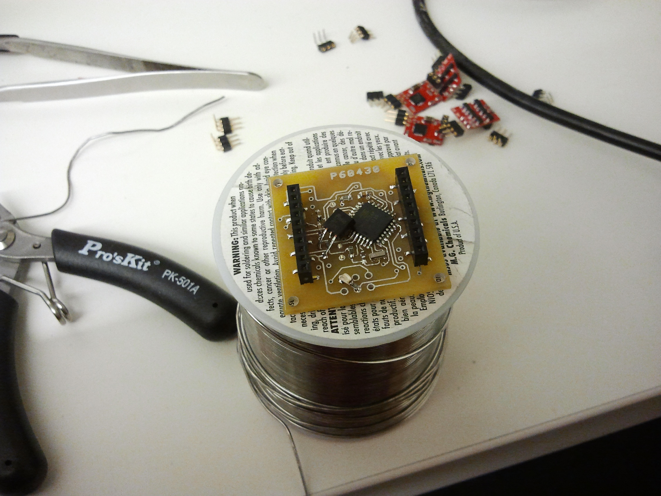
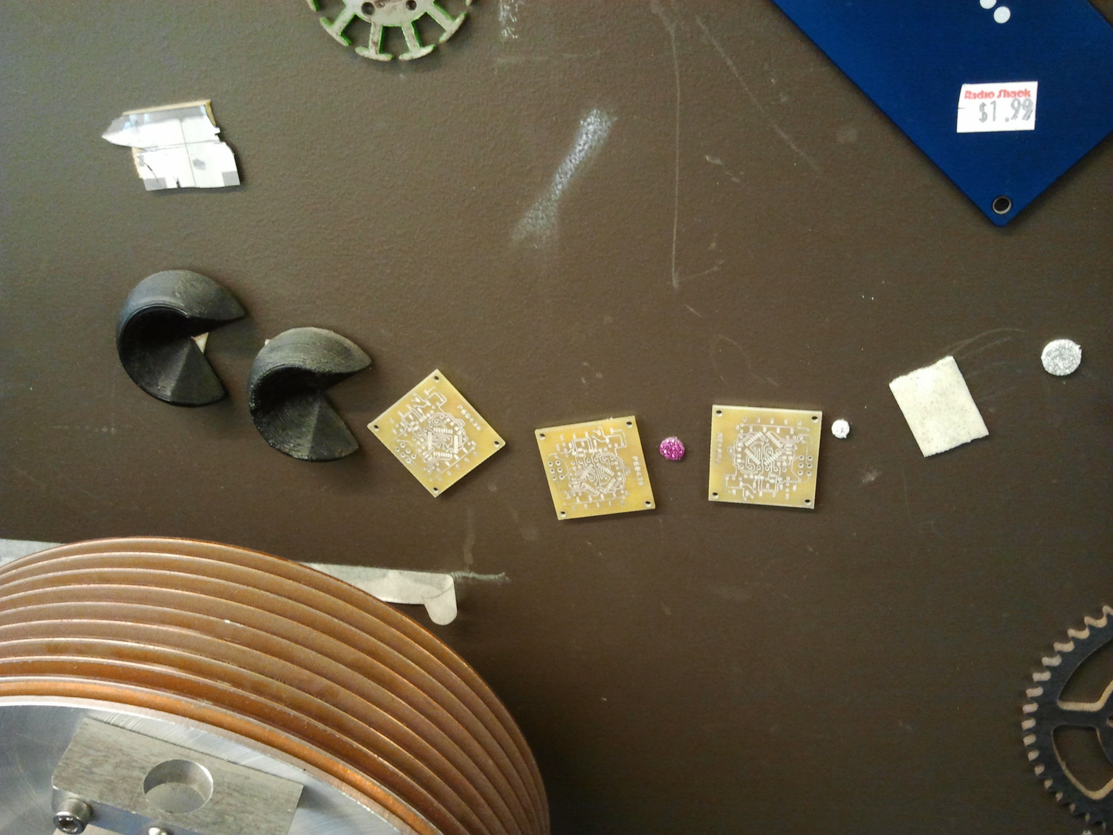
I sent these off to Advanced Circuits (saying 4pcb would be ambiguous now) using their Bare Bones service which gets me something only marginally better than if I had etched it myself, but allowed me to punt working on it for several days instead. So a few days ago, I got this back:

Hey, boards! Sweet….. wait a minute.
So the first picture of the routed board is actually the latest version, created after when I found out that in fact I did have space for a bunch of blinky LEDs.
I neglected to update the Gerber files, of course, and sent out the version with no LEDs instead.
第一个fail…
But look how tiny and cute they are!!
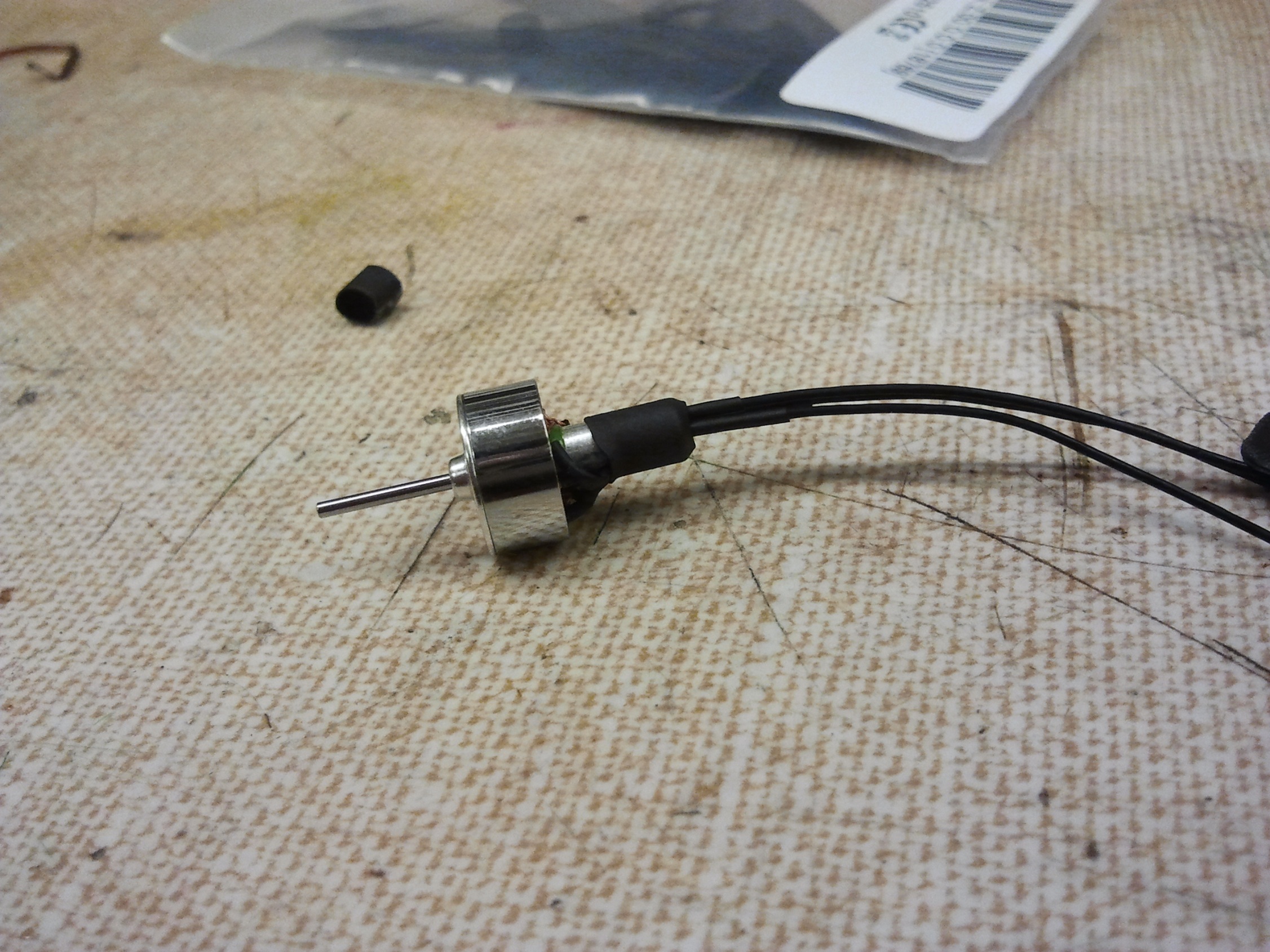
I added a single layer of heat shrink tubing to the stick mounts of the motors, since the holes for mounting them in the frame were a little bigger than intended.
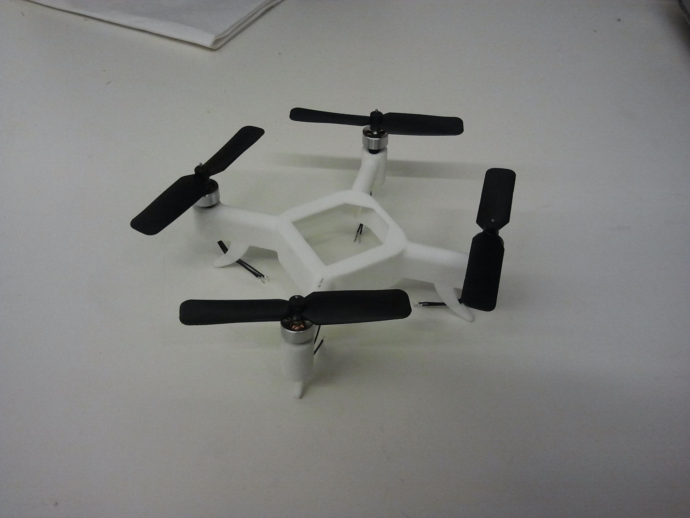
Here’s the frame with all four motors mounted. The mounting scheme is just some thick CA glue. Nothing fancy here…. but anyways,
COMMENCE THE SQUEEING IT’S SO CUTE EEEEEEEEEEEEEE
I threw this whole pile on my crack miniature scale to get a weight so far. I estimated initially that Chibicopter will weigh about 50 grams or less, with 50 grams being kind of the real “ididitrong” figure. I am confident it should end up well under.
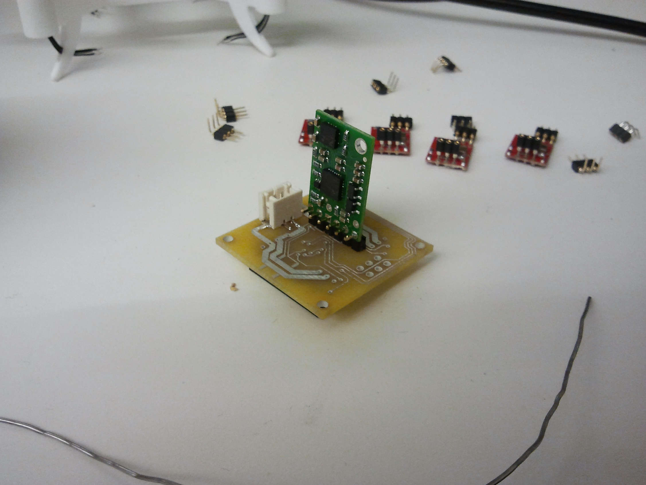
I’ve now moved onto adding parts to the board. And indeed, the decision to make the IMU stand-up is coming back to haunt me. The height of the right angle standoff and the board combined is in fact longer than its own landing legs.
Hmm. Well at least I know Chibicopter will never feel inadequate. But, it does present a problem. The solution was to cut off the black header block thing, which gained me another 2.5mm, enough to clear the landing legs.
Putting on the ATMega was quite an experience since the board was unmasked and I only had 0.5mm solder. Luckily the tip was small enough so I could make a solder blob on it, partially wipe it off, then use the remainder to “reflow” the joint. Shady, but they all worked out in the end.
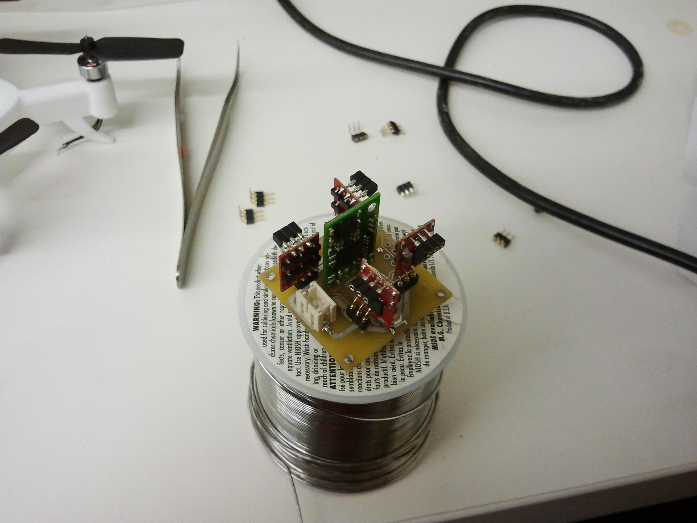
The high-rise parts now go in. About this point was where I realized that the battery plug and the reset button were both between two very tall motor driver boards and would be difficult to reach. Chalk it up to Revision 1.0 – now, wouldn’t I have looked silly if I tried to Kickstart this?!
第二个fail: Forgetting that SOT23 is not the same as SOT223.
Oops.
I “remembered” that I had some SOT-23 small FETs left over from making the Skatroller to handle the level shifting between 3.3 and 5v. In this design, one is used to buffer the XBee so it can properly reset the ATmega so the Arduino bootloader can run.
Well, it turned out that they were indeed SOT223. And that extra 2 matters alot, since SOT23s are small and SOT223s are definitely not.
To bypass this, I chopped the leads off a TO-92 packaged 2n7000 signal FET and contorted it into position.
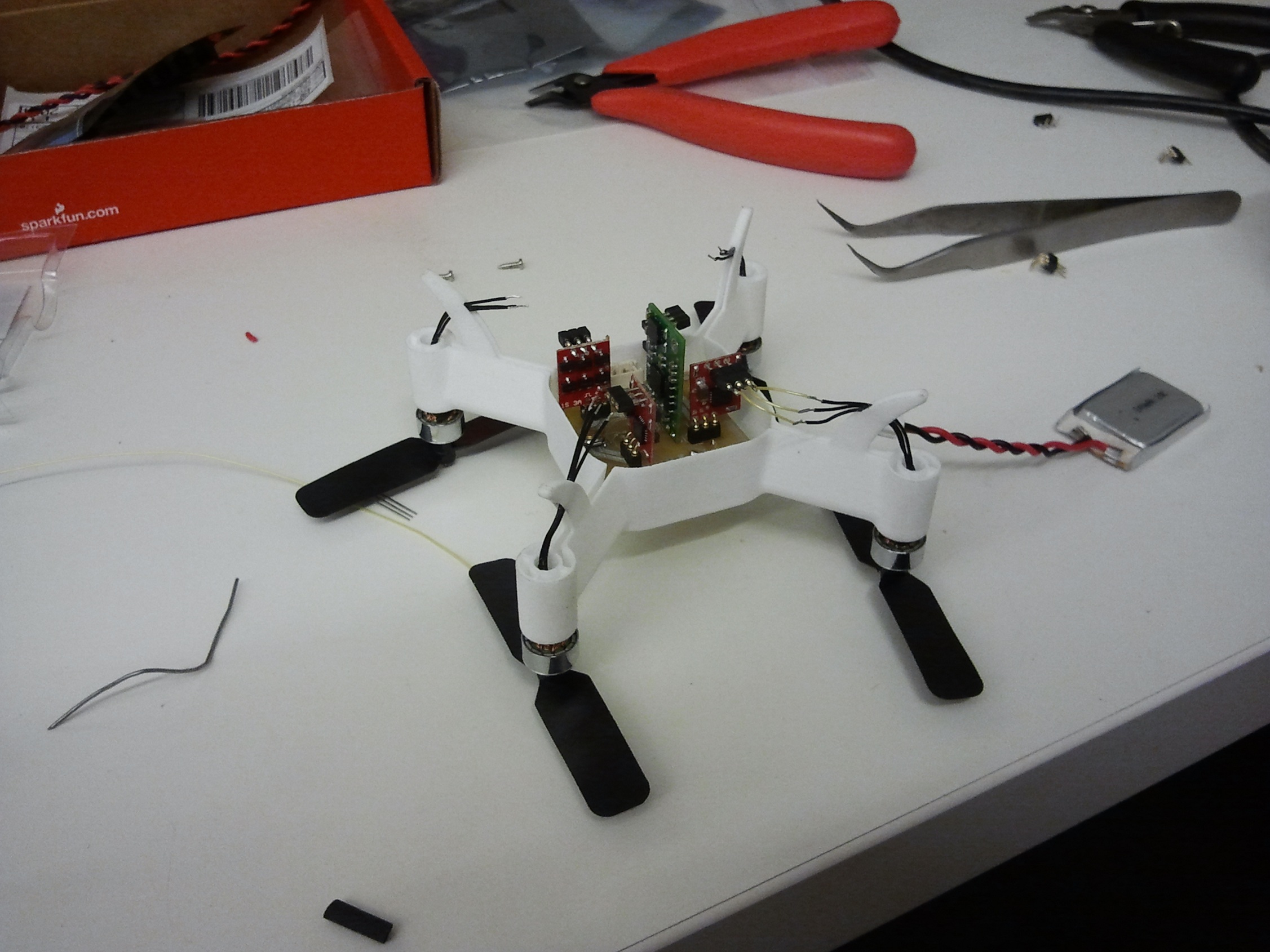
The board mounts in the body cavity like so.
I both realize the cavity doesn’t need to be as big as it is, and think it needs to be bigger so I can fit these damn boards all lay-down style… So many things to try for version 2.0, and I haven’t even finished version 1.0 yet.
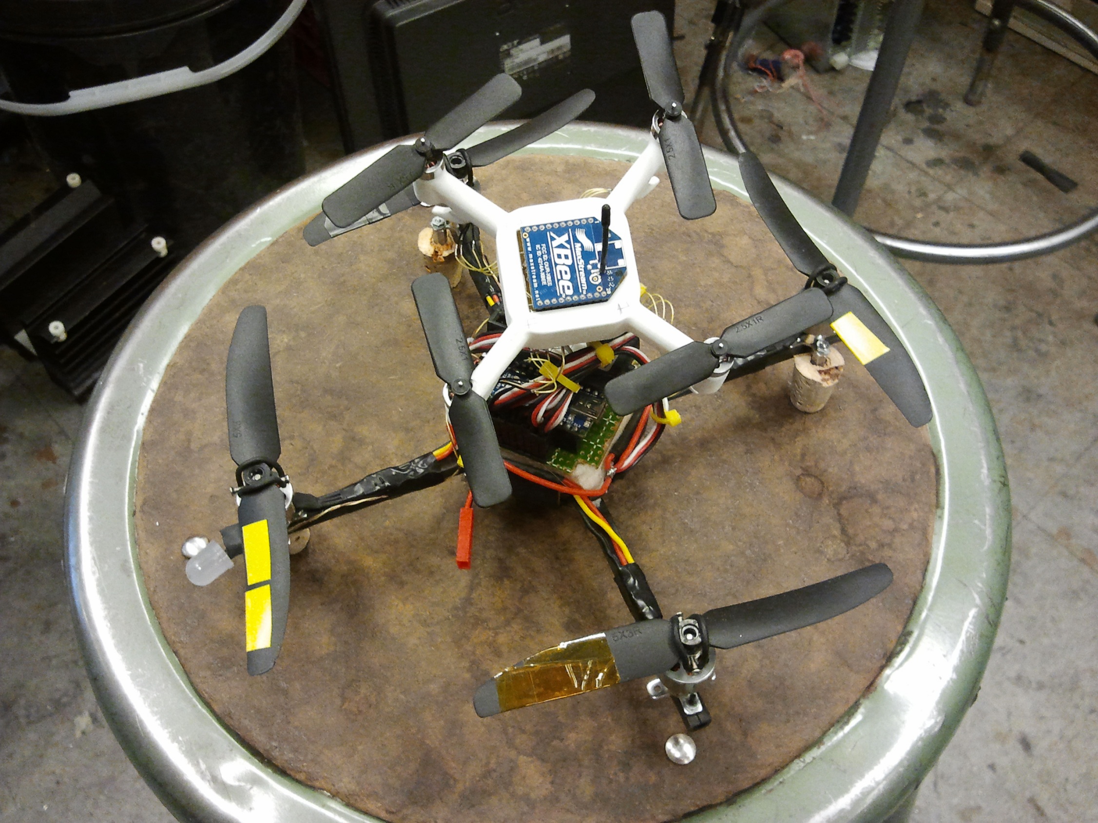
Sounds normal! In this picture I’ve also prepared the single 240mAh 20C lithium cell with a matching JST connector.
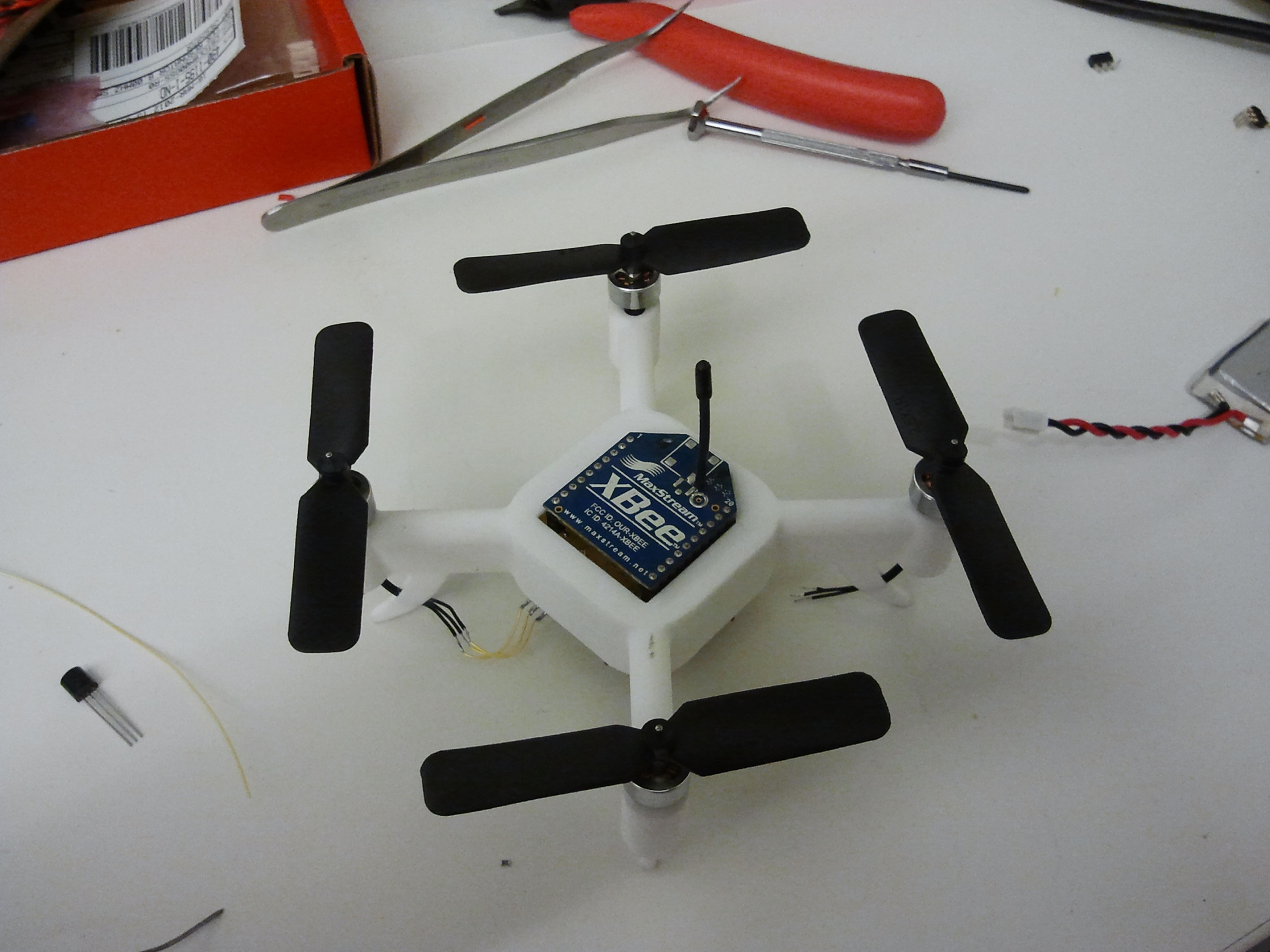
Now with more XBee.
IT’S SO CUTE IT MAKES ME WANT TO SQUEE ALL OVER AGAIN EEEEEEEEEEEEEEEEEEEEE

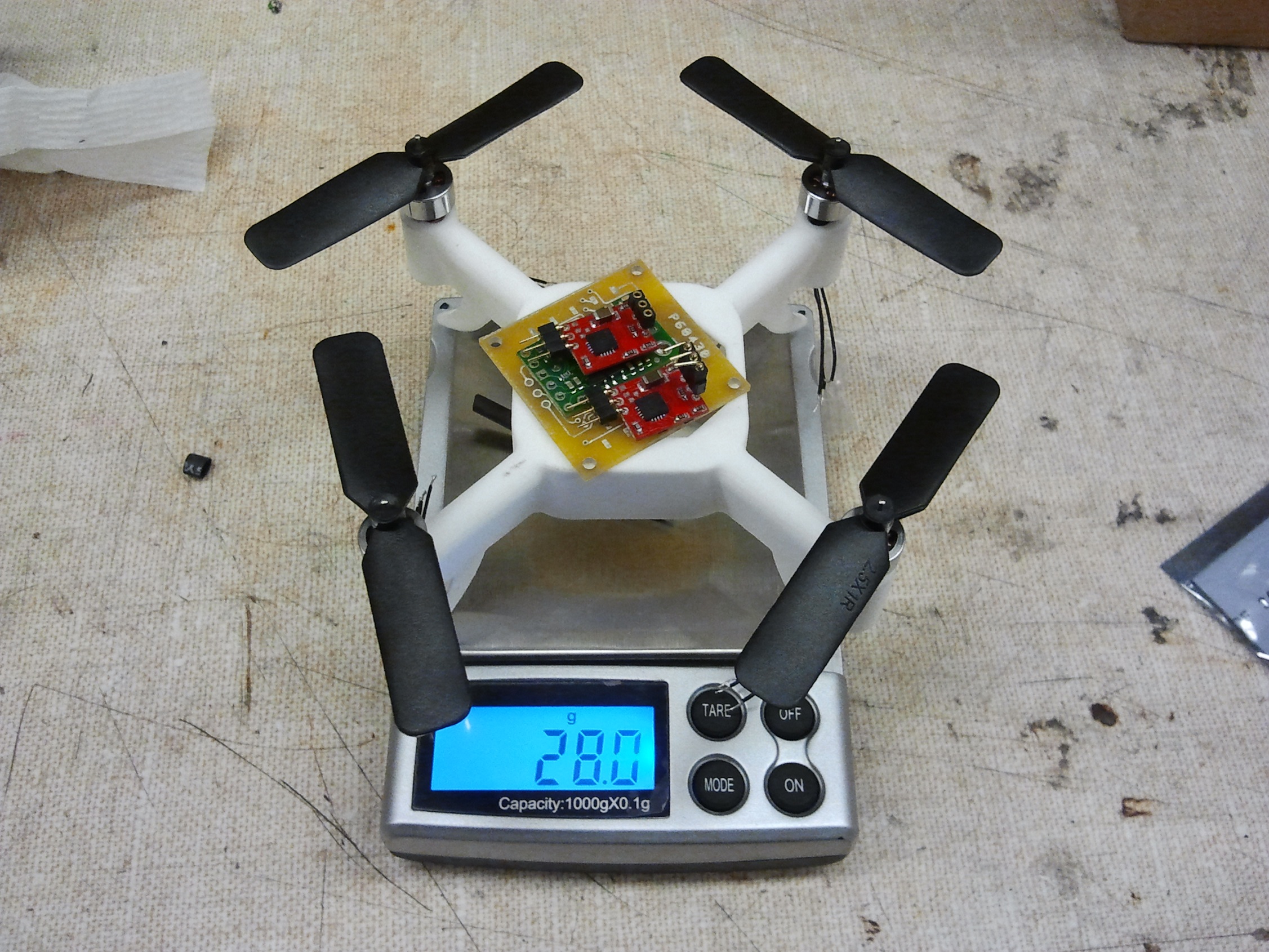
With everything installed, even the little extension harnesses I had to make for the motors, Chibicopter weighs in at just 31 grams!
But that’s without the battery. Once I drop the 240mAh cell on top, with its length of wire lead, the total weight becomes 36.6 grams.
And I assume that once I add the program in it will be more like 37 grams, right? Isn’t that what happens when you upload code?
nondeterministic PCB layout
Chibicopter’s version 1 board isn’t without its faults. For one reason or another, I had to make three little wire jumps to get everything to work.

Normally in my schematic captures, I explicitly put a “dot” junction on EVERY connection from part to net, or between wires, etc. I’ve been bitten by Eagle’s mysterious reluctance to connect two wires before. This time it seems like I let my guard down – there were 3 entire nets which visually appeared to be connected in the schematic, but none of it ported over to the layout!
This kind of pissed me off alot. Part of it was, admittedly, my fault for not double checking “hey, wait, why is one of my servo signal pins not connected to anything?” and “why are 2 of my ISP header pins empty?”, caused at least in part by routing this board at 5 in the morning.
I also slipped into a different grid spacing at least once by accident during schematic drawing, so who knows – maybe it’s some weird Eagle thing that caused wires not to connect to component pins.
Whatever. The 3 wire jumps needed, the transistor hack, and the lack of LEDs in the board revision I mistakenly sent out meant that I didn’t feel bad at all writing off $40 of boards.
These will serve better as door decor for MITERS. I can do better than this pile of crap.
To come: actually programming the damn thing. I’m hedging the whole project off the fact that the Adafruit wireless bootloading method (Adabooting?) will work as described – my XBee hookup is pretty much identical to that guide.
Refer to this:
‘A’ is the wire tool and it, despite its name is not for creating wires.
You want ‘B’, the ‘net’ tool.
It will work much better for you.
Once I figured that out, i like eagle a lot better.
DOH! forgot to fill in the link option…
Refer to this
‘A’ is the wire tool and it, despite its name is not for creating wires.
You want ‘B’, the ‘net’ tool.
It will work much better for you.
Once I figured that out, i like eagle a lot better.
D’AAAAAAAAAAAAAAAAAAAAAAAWWWWWWWWWWWWWWWWWWWWWWWWWWWWWWWWWWWWWWWWWWWWWWWWWWWWWWWWWWWWWWWWW